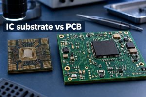
Here is how to export Gerber files from KiCad for manufacturing: create one Gerber file for each required PCB layer and separate drill files for holes and slots. Most fabricators expect both sets in one ZIP. Gerbers without drill data omit the hole pattern, while a native KiCad board file leaves the final plot choices to someone else.
The instructions match KiCad 10 and follow the files from the saved board through GerbView and into a revision-controlled ZIP. Older releases may label the menu differently, although File > Plot opens the plotting dialog in many earlier versions.

What Should You Check Before Exporting Gerber Files from KiCad?
Check the KiCad source design before creating manufacturing files. The plotter reproduces the board as it exists; it does not repair an open outline, an unconnected net, an omitted layer, or an outdated copper-zone fill. Open the final production revision in PCB Editor and save it before running the checks.
- Run the Design Rules Checker: Use Inspect > Design Rules Checker and review violations, unconnected items, and schematic-to-PCB differences. Resolve real problems and document any deliberate exclusions instead of assuming the fabricator will interpret them.
- Validate Edge.Cuts: Confirm that the external outline is one closed, non-self-intersecting shape and that intended internal cutouts are also closed. KiCad shades a valid closed board area and reports malformed outlines through DRC.
- Confirm the copper stack: Verify the enabled copper-layer count and order in Board Setup. A 4-layer board must have the correct internal layers and stack sequence before those layers are plotted.
- Review mask and silkscreen: Check mask openings around pads and make sure silkscreen text and graphics do not cover exposed solderable areas. Remove information that does not belong on the manufactured board.
- Inspect drilled features: Review plated through holes, non-plated holes, slots, and mounting holes. Confirm that each feature has the intended plating property and finished purpose.
- Refill copper zones: Press B or use the zone-fill command, then save the board. Enabling KiCad’s plot-time zone check provides another safeguard, but the source board should already be current.
This preflight checks the editable design. It does not replace the later Gerber review, which checks the actual files that will leave your computer.
How to Export Gerber Files from KiCad Step by Step?
Use PCB Editor to export Gerber files from KiCad into a clean revision folder, then inspect what KiCad actually wrote. Each step below keeps the output tied to the same saved board revision and ends with something you can check.
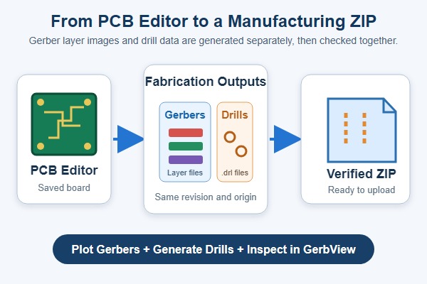
- Open the final board in PCB Editor: Confirm the project name and revision, save the .kicad_pcb file, and make sure the canvas shows the board you intend to order.
- Open the Gerber dialog: Choose File > Fabrication Outputs > Gerbers (.gbr). File > Plot opens the same dialog when Gerber is selected as the plot format. The Plot window should show the board’s enabled layer list.
- Choose a dedicated output folder: Use a new folder such as fabrication/rev-b/gerber. It should not contain files from an earlier revision. The output path displayed in the dialog should point to that folder.
- Select the required layers: Include every copper layer used by the design, the top and bottom solder-mask layers, any silkscreen layers that contain board markings, and Edge.Cuts. Add paste layers only when the package also serves a stencil or assembly workflow.
- Set the relevant plot options: Keep the drawing sheet out of the Gerbers, keep the plot at its real scale, use a consistent origin, and enable the zone-fill check. Change compatibility options only when your manufacturer provides a requirement.
- Click Plot: KiCad writes one Gerber file for each selected layer. Review the Output Messages panel and open the destination folder. You should see a fresh set whose timestamps match this export.
Do not ZIP the folder yet. First confirm the layer set, generate the drill output, and inspect both together.
Which Gerber Layers Should You Export for PCB Manufacturing?
A bare PCB package normally includes every used copper layer, both solder-mask layers, the required silkscreen layers, and Edge.Cuts. The exact count changes with the board stack and whether artwork exists on the back. The table separates bare-board files from stencil or assembly outputs.
| Layer | Purpose and Export Rule |
|---|---|
| F.Cu | Front copper image; always export it when the board uses front copper. |
| B.Cu | Back copper image; always export it for a 2-layer or multilayer board. |
| In1.Cu, In2.Cu, and other internal copper | Inner signal or plane layers; export every enabled internal layer in the correct stack order. |
| F.Mask | Front solder-mask openings; normally required. |
| B.Mask | Back solder-mask openings; normally required. |
| F.Silkscreen | Front legend and reference markings; export when used. |
| B.Silkscreen | Back legend and reference markings; export when used. |
| Edge.Cuts | External profile and internal cutouts; required for the manufactured board shape. |
| F.Paste and B.Paste | Solder-paste stencil apertures; use for stencil or assembly preparation, not normally for bare-board fabrication. |
| F.Fab and B.Fab | Assembly and fabrication drawing detail; send separately when requested and never substitute it for copper or Edge.Cuts. |
For a typical 2-layer bare board, the practical minimum is F.Cu, B.Cu, F.Mask, B.Mask, Edge.Cuts, the silkscreen layers that contain artwork, and the drill file or files. For a multilayer design, add every internal copper layer and provide the intended stackup separately so the manufacturer can map the layer order without guessing.
Which KiCad Gerber Plot Settings Matter for PCB Manufacturing?
Keep the defaults that preserve 1:1 geometry, then change only options that affect file interpretation or compatibility. KiCad exposes many plot controls because the same dialog can also create PDF, SVG, DXF, and other outputs. A Gerber handoff uses a smaller, more focused subset.
- Plot drawing sheet: off: The page border and title block are document furniture, not the PCB profile. Edge.Cuts should carry the board shape.
- Check zone fills before plotting: on: KiCad warns that plot output can be wrong when outdated zones are not checked and refilled.
- Plot on all layers: normally empty: This feature overlays selected items onto every base layer. Use it only for a deliberate documentation requirement, not to place Edge.Cuts or silkscreen into every Gerber by habit.
- Gerber X2: use when accepted: X2 adds file-function, net, and other attributes that can help CAM interpretation. Turn it off only when a manufacturer reports that its older CAM system cannot process X2.
- Protel filename extensions: optional: This changes names such as .gbr to familiar extensions such as .GTL and .GBL; it does not change the board geometry. Follow the recipient’s naming preference.
- Gerber job file: useful but not a replacement: A .gbrjob file can carry stackup, material, and finish metadata. Keep the ordinary layer files and fabrication notes because not every CAM flow relies on the job file.
- Coordinate format: manufacturer-bound: Use the fabricator’s recommendation when one is published. Do not change precision merely because an older tutorial shows a different KiCad release.
- Origin: keep it consistent: Absolute origin is a common default when the manufacturer does not specify otherwise. If you use a drill/place origin, apply the same origin to the Gerber and drill outputs.
The current option definitions and compatibility notes are documented in the KiCad 10 PCB Editor manual. A manufacturer’s written CAM requirement takes precedence over a generic screenshot.
How Do You Generate Drill Files in KiCad?
Generate the drill data separately after plotting the Gerber layers. From the Plot dialog, click Generate Drill Files, or use File > Fabrication Outputs > Drill Files (.drl). Point the drill dialog to the same revision-specific output folder and keep its origin consistent with the Gerbers.
- Choose Excellon for broad compatibility: KiCad states that most PCB manufacturers require Excellon. Use Gerber X2 drill output only when the recipient explicitly accepts it.
- Leave Mirror Y axis off: KiCad advises against mirroring when a third party manufactures the PCB.
- Leave Minimal header off: Enable it only when the manufacturer asks for a reduced header.
- Keep PTH and NPTH separate by default: KiCad normally writes plated and non-plated holes to separate Excellon files. Merge them only when the manufacturer requests a single drill file.
- Keep alternate oval-hole mode off: The normal route-command representation suits most manufacturers. Use the alternate mode only for a stated CAM requirement.
- Generate and inspect the output: Click Generate, confirm that the messages contain no unresolved errors, and verify that the expected .drl file or files appear with the new Gerbers.
A drill map can help a human review the hole pattern, but it does not replace the machine-readable drill file. If blind, buried, or laser-drilled vias are involved, also send the stackup and via-span requirements because a flat file list does not fully describe the fabrication sequence.
How Do You Verify KiCad Gerber and Drill Files Before Manufacturing?
Load the exported Gerber files and Excellon drill files together in GerbView and inspect the manufacturing data, not the original PCB canvas. KiCad’s Gerber Viewer lets you switch layers on and off, compare their alignment, and view drill data over the copper and outline.
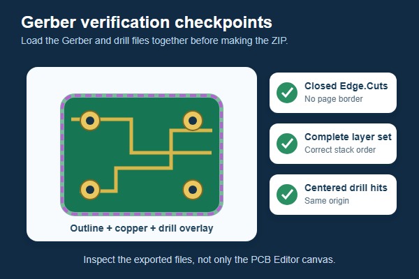
- Load the complete export: Open all Gerber layers, then load every Excellon drill file. The correct result is one entry for every expected copper, mask, silkscreen, profile, and drill output, with no file from an older revision.
- Check the board outline: Edge.Cuts should show one continuous external profile plus only the intended internal cutouts. The displayed dimensions should match the source design, without a page border or unexpected outer rectangle.
- Inspect copper in stack order: Toggle each copper layer and check that its routing, pads, planes, and board position belong to that layer. A multilayer set should contain every intended copper layer once, in the expected order.
- Compare mask with pads: Solder-mask openings should align with exposed pads, test points, and other intended copper. Unexpected solid mask over a pad is a reason to return to the source board.
- Review silkscreen clearance: Text should remain readable, appear on the intended side, and stay off exposed pads. In the finished-board view, bottom-side text should have the expected orientation rather than looking accidentally mirrored.
- Overlay drill hits: Plated holes should sit inside their pads, while non-plated mounting holes and slots should align with the outline and mechanical features. A consistent offset across the board points to mismatched origins.
- Check high-risk details: Zoom into fine-pitch footprints, connector rows, mounting holes, slots, board-edge features, and dense via fields. The correct export should preserve the same clearances and feature positions you approved in the source board.
A successful Plot message proves that KiCad wrote files; it does not prove that you selected every required layer or that the output represents the intended revision. When anything looks wrong, repair the source board, delete the affected export set, regenerate Gerbers and drills together, and repeat the viewer inspection.
What Should a Complete KiCad PCB Manufacturing Package Include?
Gerber files describe layer images and board geometry, but they do not communicate every manufacturing requirement. A complete handoff combines the exact files you inspected with the construction details that a fabricator cannot safely infer from those images.
- Verified Gerber set: Include the same complete layer set that you loaded and checked in GerbView, without files from another revision.
- Machine-readable drill data: Include the Excellon PTH and NPTH output generated for that Gerber set. A drill map is useful for review but is not a production drill file.
- Stackup and construction details: State the layer order, material, finished thickness, copper weight, and any blind, buried, laser-drilled, filled, or capped via requirements.
- Fabrication notes: Specify surface finish, controlled impedance, critical tolerances, panelization, special routing, and other order-specific requirements.
- Optional Gerber job file: Include the .gbrjob file when generated and accepted, but do not use it instead of the individual Gerber, drill, and fabrication files.
If the same project also includes assembly, the assembler may request a BOM, component placement file, assembly drawings, paste layers, programming data, and test instructions. Those are PCBA inputs and should not be confused with the bare-board Gerber and drill package.
How Should You Package and Send KiCad Gerber Files to a Manufacturer?
Create the ZIP from the exact folder you inspected, then keep that verified archive unchanged for upload. This simple rule prevents a late file replacement from breaking the relationship between the viewer check and the package that reaches the manufacturer.
- Start from an empty revision folder: Remove or archive the previous output before plotting. Never mix a new copper layer with an old outline or drill file.
- Generate Gerbers and drills in one session: Matching timestamps are not a substitute for revision control, but they make accidental carryover easier to spot.
- Verify that exact set: Load the folder’s Gerbers and drills into GerbView. Do not inspect one folder and ZIP another.
- Use a clear archive name: Include the project and revision, such as controller-rev-b-fab.zip, without spaces or ambiguous words such as final-final.
- Attach the fabrication notes: State quantity, material, stackup, finished thickness, copper weight, surface finish, impedance requirements, tolerances, delivery location, and any special process requirement that is not unambiguously encoded in the image files.
- Review the manufacturer’s preview: If the upload portal renders the ZIP, compare the outline, layer count, dimensions, and drill pattern with your verified GerbView result before placing the order.
A .kicad_pcb file can be useful for engineering discussion, but it is not a universal substitute for fabrication output. Send it only when the manufacturer accepts native KiCad data and you are comfortable sharing the editable design. Keep the approved Gerber and drill archive as the order’s controlled manufacturing package.
Which KiCad Gerber Export Mistakes Cause Manufacturing Problems?
The most consequential errors are missing outline or drill data, wrong layer selection, mixed revisions, and inconsistent origins. The first symptom usually points to a narrow check, so correct the source or export decision instead of changing unrelated settings.
| Issue | Impact and First Fix |
|---|---|
| Edge.Cuts missing or open | The board outline cannot be interpreted correctly. Close the outline and re-export Edge.Cuts. |
| Drill files omitted | Holes and vias are missing. Generate and include the Excellon drill files. |
| NPTH file omitted | Mounting or tooling holes may be missing. Include the separate NPTH drill file. |
| Inner layer missing | Multilayer connectivity may be incorrect. Check the stackup and re-export all copper layers. |
| Gerber and drill origins differ | Drill hits are shifted from pads. Use the same origin for both outputs. |
| Mixed revisions | Layers and holes may not align. Clear the output folder and export one revision. |
| Wrong extra layers included | The manufacturing package becomes ambiguous. Remove unrelated paste or fabrication outputs. |
| Files not inspected | Missing or shifted output may go unnoticed. Verify the exported files in GerbView. |
Silkscreen over exposed pads is another frequent review finding, but it is not solved by selecting more files. Correct the source artwork or use the approved silkscreen-to-mask handling, then regenerate and inspect the affected silkscreen and mask layers.
FAQs About KiCad Gerber Export
Q1: Does the .gbrjob file include the drill data?
A1: No, the .gbrjob file does not include drill data. KiCad creates it as part of the Gerber export, while hole data is generated separately. Include the Excellon .drl files even when a .gbrjob file is present.
Q2: Can a drill map replace the .drl file?
A2: A drill map cannot replace the .drl file. It is a visual aid for reviewing hole locations and tool sizes. The manufacturer still needs the machine-readable drill file, normally in Excellon format.
Q3: How should slots and internal cutouts be included?
A3: Put board cutouts on Edge.Cuts and configure slots through their pad or drill properties. Use closed shapes for cutouts and set the correct plating property for each slot. Open the Gerbers and drill files together to confirm that every routed feature is present and aligned, and follow the manufacturer’s minimum slot and routing rules.
Q4: Why does the manufacturer’s preview show a full sheet or an oversized board?
A4: A page border or stray item is probably expanding the preview. Check that Plot drawing sheet is off, Edge.Cuts contains one valid closed outer profile, and Edge.Cuts was not added to every layer through Plot on all layers. The preview should show the board outline, not a full page or an unexpected rectangle.
Q5: Can KiCad open or edit the Gerber files after export?
A5: Use GerbView to inspect Gerbers, not as a substitute for the KiCad source design. GerbView can export limited geometry to PCB Editor, but that conversion does not recreate the original netlist, footprints, constraints, or full design intent. Make changes in the .kicad_pcb source, then export a new manufacturing set.
Q6: Do Gerber files include the BOM and component placement data?
A6: Gerber files do not include the BOM or component placement data. They describe the board’s fabricated layer images. Automated assembly normally requires a BOM and a component placement or centroid file in addition to the PCB manufacturing package.
Q7: Should I use different KiCad settings for JLCPCB or another manufacturer?
A7: Follow the manufacturer’s current requirements when they differ from KiCad’s general defaults. The essential checks stay the same: export every required layer, generate the drill files separately, keep the origins consistent, and inspect the exact upload package. A board-house profile does not replace GerbView inspection or the portal preview.
A reliable KiCad handoff comes from four controls: a checked source board, a complete layer and drill export, a viewer inspection of the actual files, and separate notes for requirements that images cannot fully express. That sequence is more dependable than copying a settings screenshot from a different KiCad release or manufacturer.
Once your KiCad Gerber and drill files have been verified, send the ZIP together with your stackup, material, copper weight, surface finish, impedance requirements, quantity, and delivery requirements to sales@bestpcbs.com. EBest Circuit can review the manufacturing package before PCB fabrication and provide a quotation based on the actual board requirements.