PCB manufacturing PCB manufacturing
Home > Blog

IPC Class 3 PCB

IPC Class 3 PCB: Requirements, Rules & Class 2 Differences
Thursday, July 30th, 2026
An IPC Class 3 PCB is intended for electronics that must operate reliably under demanding conditions. A failure may cause a safety risk, costly downtime, loss of an essential function, or difficult field repair.A Class 3 product is not created by adding one sentence to a PCB drawing. The design, fabrication process, assembly workmanship, inspection plan, testing, and documentation must support the same reliability target.

This guide explains IPC Class 3 PCB requirements, how Class 3 differs from Class 2, which standards apply, and what buyers should provide when requesting a PCB or PCBA quotation.
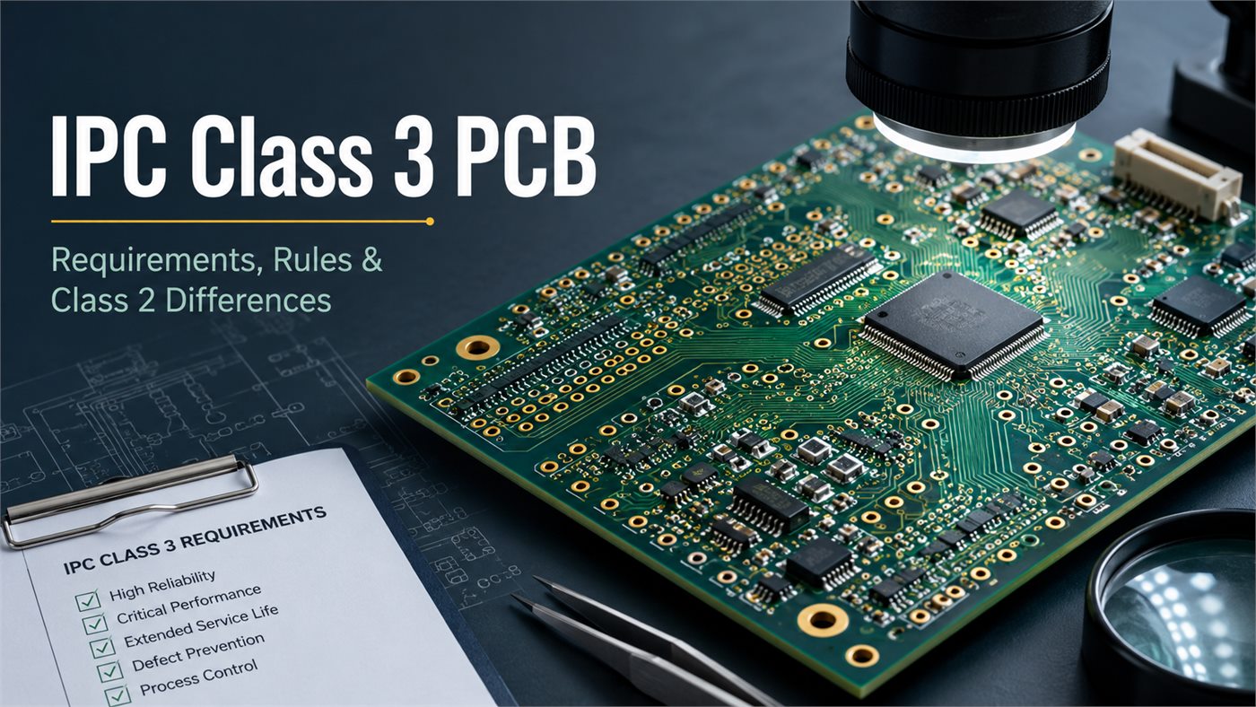
IPC Class 3 PCB requirements, rules, and Class 2 differences

What Is IPC Class 3?

IPC Class 3 applies to high-performance electronic products that require dependable operation and long service life. It is commonly specified when equipment must function on demand or continue working in a harsh or safety-related environment.

Class 3 may be appropriate when:

  • A failure could interrupt a critical system.
  • Repair or replacement is difficult.
  • The equipment faces vibration, humidity, shock, or thermal cycling.
  • The customer contract explicitly requires Class 3.
  • Detailed traceability and inspection records are necessary.

Class 3 does not refer to one laminate, copper thickness, surface finish, or PCB construction. FR4 PCBs, HDI boards, rigid-flex circuits, metal-core PCBs, and high-frequency boards can all be produced to Class 3 when the design and process controls support it.

Which IPC Standards Apply to Class 3 PCB and PCBA?

No single IPC document controls the complete product. Different standards cover PCB design, bare-board fabrication, soldering processes, and finished assembly acceptance.
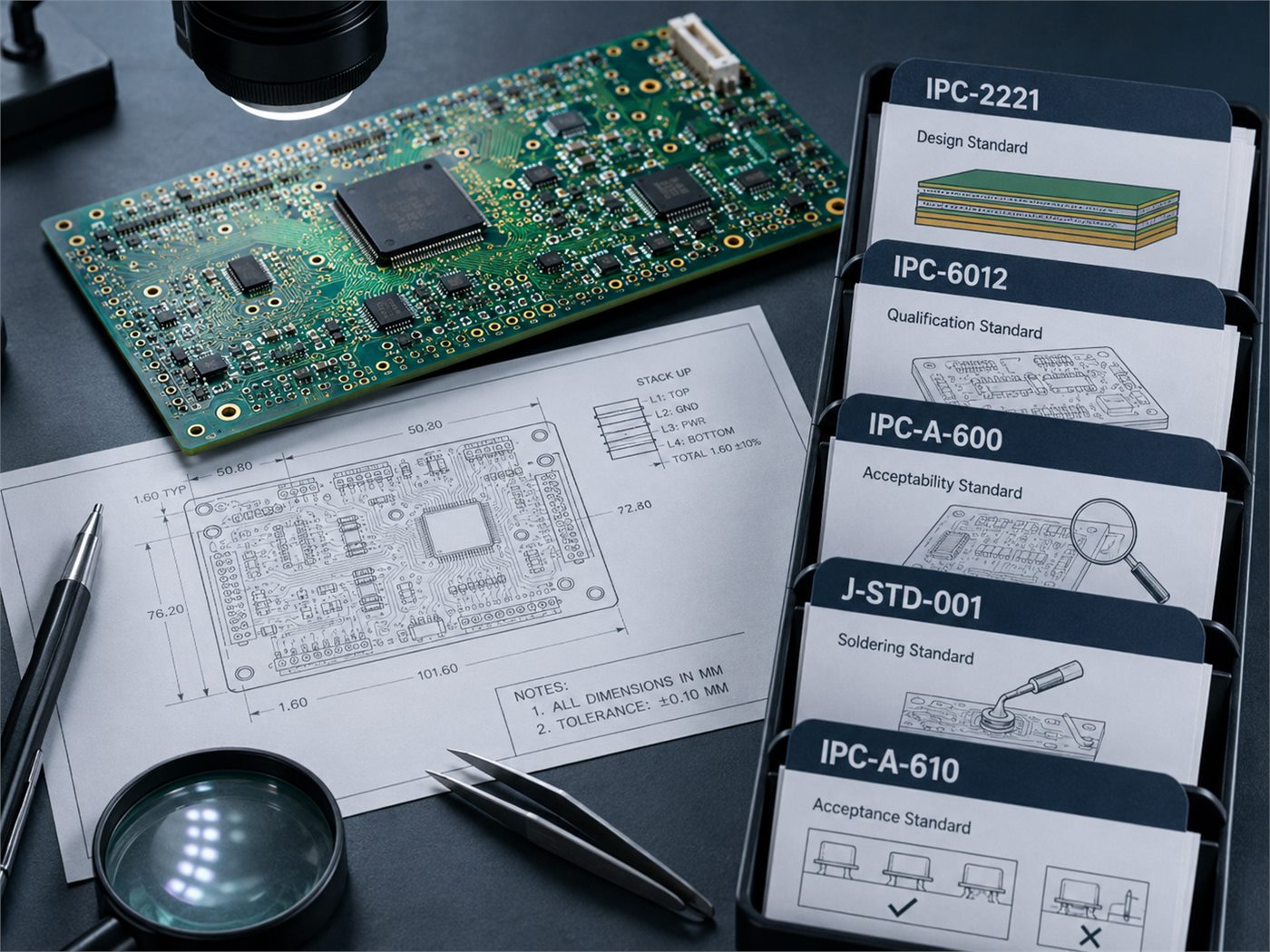
IPC standards applicable to Class 3 PCB and PCBA production
Standard Main application
IPC-2221 General PCB design requirements
IPC-6012 Rigid PCB qualification and performance
IPC-A-600 Bare PCB acceptability
IPC-6013 Flexible and rigid-flex PCB performance
J-STD-001 Soldering materials, processes, and workmanship
IPC-A-610 Finished electronic assembly acceptance
IPC-7351 Surface-mount land-pattern guidance
IPC-7711/7721 PCB and PCBA rework and repair

A rigid PCB assembly may reference:

  • IPC-2221 for design
  • IPC-6012 Class 3 for bare-board performance
  • IPC-A-600 Class 3 for bare-board acceptance
  • J-STD-001 Class 3 for soldering
  • IPC-A-610 Class 3 for assembly acceptance

Rigid-flex projects normally use IPC-6013 as the relevant performance standard.

The drawing should identify the required revision level. Do not assume that the latest revision should automatically replace the version stated in a regulated, aerospace, medical, or legacy program.

IPC Class 1 vs Class 2 vs Class 3

IPC product classes reflect different service and reliability expectations. They are not simply low-, medium-, and high-quality grades.
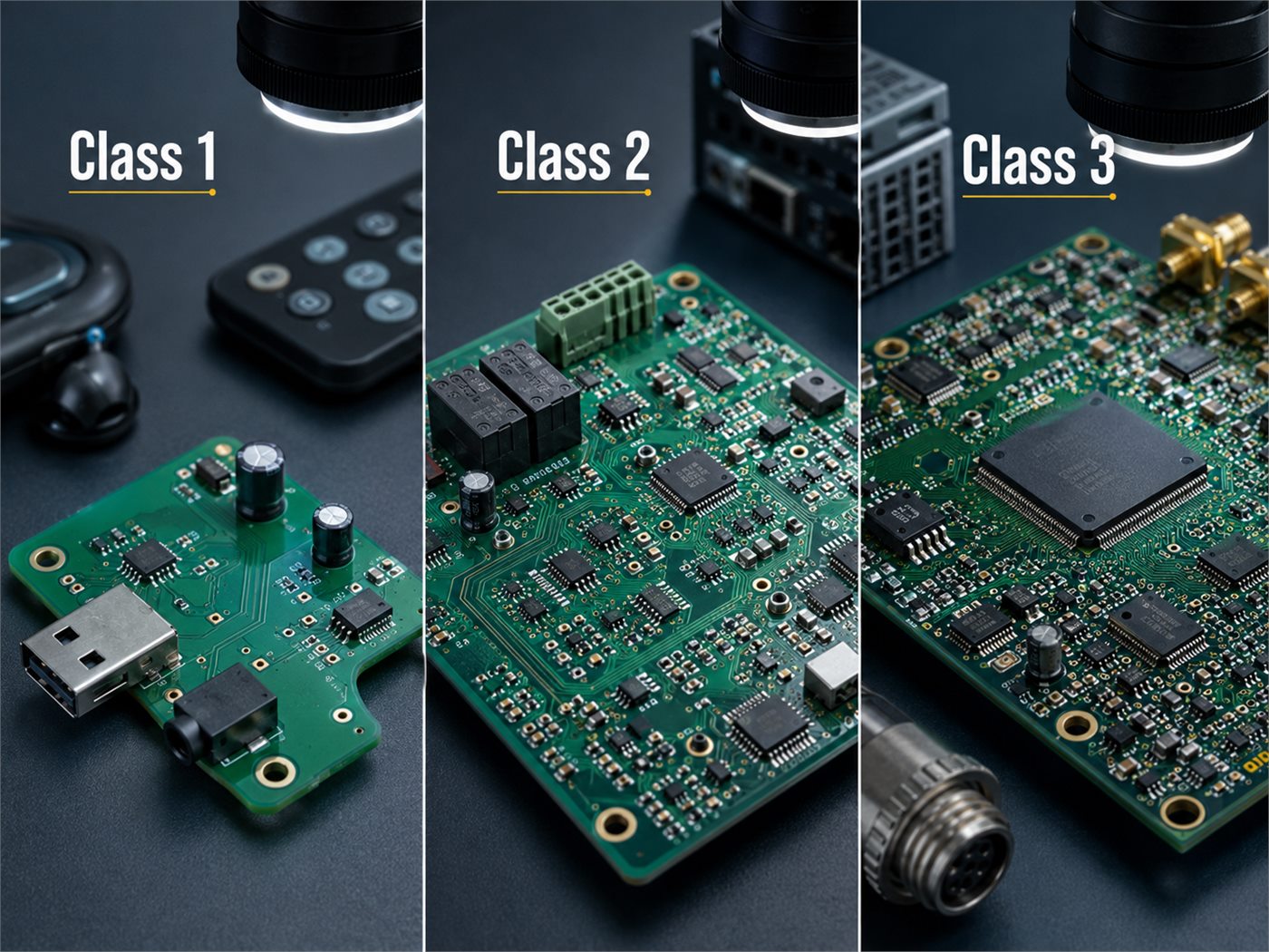
Visual comparison of IPC Class 1, Class 2, and Class 3 printed circuit boards
Class Product expectation Typical applications
Class 1 Basic operation and limited service life Disposable and low-cost consumer electronics
Class 2 Continued operation and normal service life Industrial controls, computers, instruments, communication products
Class 3 High reliability and performance on demand Aerospace, defense, critical medical, railway, and safety systems

Class 2 is sufficient for many commercial and industrial products. Class 3 becomes justified when the consequence of failure outweighs the additional design, inspection, testing, and documentation cost.

The industry does not automatically determine the class. A medical accessory may use Class 2, while an emergency shutdown controller may require Class 3.

IPC Class 2 vs Class 3: What Are the Main Differences?

Class 2 and Class 3 boards may be built on the same production equipment. The main differences are design margin, acceptance limits, inspection, process evidence, and traceability.

Area IPC Class 2 IPC Class 3
Reliability target Continued commercial or industrial service High reliability and operation on demand
Annular ring More process allowance may be accepted Tighter remaining annular-ring control
Plated holes Standard commercial criteria Stricter structural and plating criteria
Registration Normal production tolerances Tighter hole and layer registration
Inspection Standard production inspection More verification and documentation
Traceability Project-dependent Often more detailed
Assembly Class 2 workmanship Class 3 workmanship and acceptance
Cost Lower Higher
Lead time Standard May increase due to testing and reporting

The class should be selected before layout release. A PCB with marginal annular rings, small drill-to-copper clearances, or weak microvia structures may require redesign before it can be manufactured reliably to Class 3.

What Are the Main IPC Class 3 PCB Design Requirements?

A Class 3 design needs enough manufacturing margin to remain compliant after drilling, plating, lamination, etching, and solder mask imaging.

Key design checks include:

  • Pad dimensions around plated holes
  • Finished-hole sizes and tolerances
  • Drill-to-copper clearance
  • Internal-layer registration
  • Dielectric spacing
  • Finished copper thickness
  • Controlled-impedance structures
  • Blind, buried, and microvia construction
  • Solder mask registration
  • Coupon and test access

Pad and Hole Geometry

A plated-hole pad must accommodate more than the nominal finished hole. It also needs room for drill movement, plating, layer registration, and the required annular ring.

The fabrication drawing should distinguish between:

  • Finished hole and tool size
  • Plated and non-plated holes
  • Positive and negative tolerances
  • Press-fit holes
  • Filled, capped, plugged, or open vias

Stack-Up and Impedance

The stack-up should identify dielectric materials, copper thickness, finished board thickness, and controlled-impedance layers.

A note that only states “1.6 mm FR4” is not enough when impedance, insulation distance, or thermal behavior depends on individual dielectric layers.

Controlled impedance is not automatically required for Class 3. When it is required, specify:

  • Target impedance
  • Tolerance
  • Trace layer
  • Reference plane
  • Single-ended or differential structure
  • Test coupon and report requirements

HDI Structures

Microvias, buried vias, stacked vias, and sequential laminations need construction-specific review.

Typical risks include:

  • Small target pads
  • Weak microvia interfaces
  • Incomplete copper filling
  • Excessive stacked microvia depth
  • Repeated thermal stress during assembly

Where routing density allows, staggered microvias may provide a more robust structure than long stacked microvia chains.

IPC Class 3 Via Size, Annular Ring, and Plating Requirements

There is no universal IPC Class 3 via diameter.

The correct via size depends on:

  • Board thickness
  • Finished hole size
  • Aspect ratio
  • Drilling method
  • Pad diameter
  • Plating capability
  • Layer registration
  • Reliability target
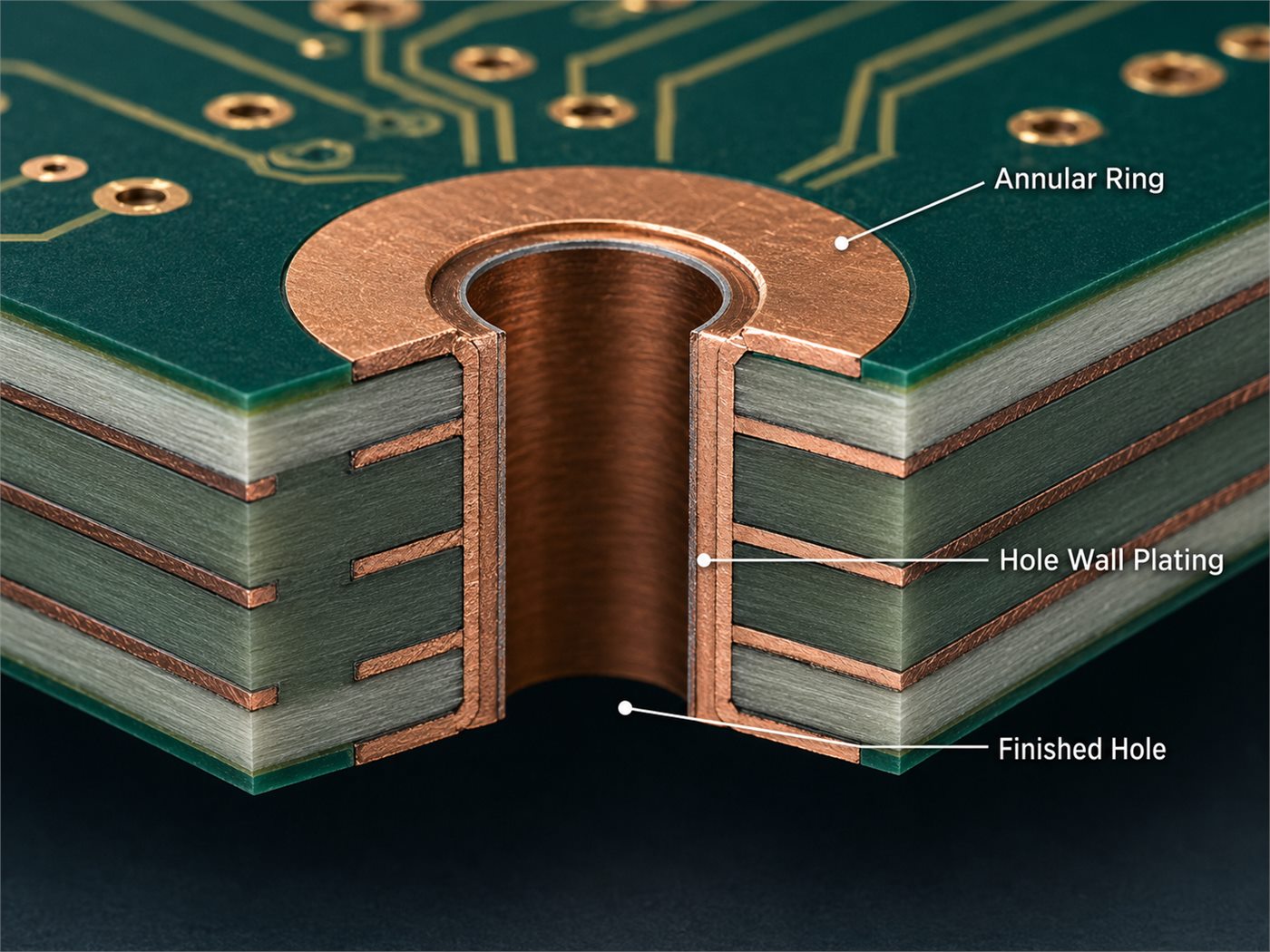
IPC Class 3 via cross-section showing annular ring, hole wall plating, and finished hole

A useful planning formula for the PCB annular ring is:

Minimum pad diameter = Finished hole + 2 × Required annular ring + Manufacturing allowance

The manufacturing allowance may include drill-position tolerance, layer registration, drill oversize before plating, etching reduction, and finished-hole tolerance.

A design may pass a CAD design-rule check and still have insufficient Class 3 manufacturing margin.

For via review, the PCB manufacturer should check:

  • Finished hole tolerance
  • Board thickness and aspect ratio
  • Internal and external annular ring
  • Hole-wall plating distribution
  • Internal-layer connections
  • Resin condition
  • Copper wrap where applicable
  • Thermal-stress performance

Microvias need separate evaluation. Hidden interface defects may not be visible during standard inspection. High-reliability HDI projects may require via-chain coupons, resistance monitoring, or thermal cycling.

IPC Class 3 PCB Manufacturing and Material Requirements

Class 3 does not require every PCB to use high-Tg FR4 or a specific laminate brand. Material selection should reflect the actual operating and assembly conditions.

Important factors include:

  • Operating temperature
  • Lead-free reflow exposure
  • Thermal cycling
  • Z-axis expansion
  • Moisture absorption
  • Frequency and signal loss
  • Mechanical stress
  • Flammability requirements

High-Tg FR4 is common in multilayer Class 3 products, but Tg alone does not determine reliability. Resin system, decomposition temperature, copper adhesion, moisture behavior, and thermal expansion also matter.

Typical manufacturing controls include:

  • Laminate and copper-foil traceability
  • Lamination registration
  • Drilling and desmear quality
  • Electroless and electrolytic copper control
  • Hole-wall plating
  • Conductor width and spacing
  • Solder mask alignment
  • Surface-finish thickness
  • Ionic cleanliness
  • Bow and twist
  • Electrical testing
  • Coupon and microsection inspection

Repair rules should be defined before production. Some programs allow controlled repair with records. Others prohibit repair on critical Class 3 features.

IPC Class 3 Assembly Requirements under J-STD-001 and IPC-A-610

IPC Class 3 PCB assembly requirements and bare-board Class 3 requirements are related, but they are not interchangeable.

J-STD-001 controls soldering materials, processes, and workmanship. IPC-A-610 is used to inspect the finished electronic assembly.

Class 3 assembly requirements may cover:

  • Through-hole barrel fill
  • Solder wetting
  • Lead condition
  • Component alignment
  • Polarity and orientation
  • Solder bridging
  • Flux residues
  • BGA and QFN joints
  • Hardware installation
  • Conformal coating
  • Rework records

Packages such as BGA, QFN, LGA, and bottom-terminated power devices often require X-ray because their solder joints cannot be fully evaluated by visual inspection.

A Class 3 assembly process may also include:

  • Solder paste inspection
  • Controlled reflow profiling
  • First-article verification
  • AOI
  • X-ray
  • Documented rework
  • ICT or functional testing

For a complete PCBA quotation, state both the bare-board and assembly requirements. An IPC-6012 Class 3 PCB order does not automatically instruct the assembler to apply J-STD-001 and IPC-A-610 Class 3.

What Inspection, Testing, and Documentation Does Class 3 Require?

The test plan should address the actual construction and failure risks. Ordering every available test can raise cost without improving the most relevant reliability concern.
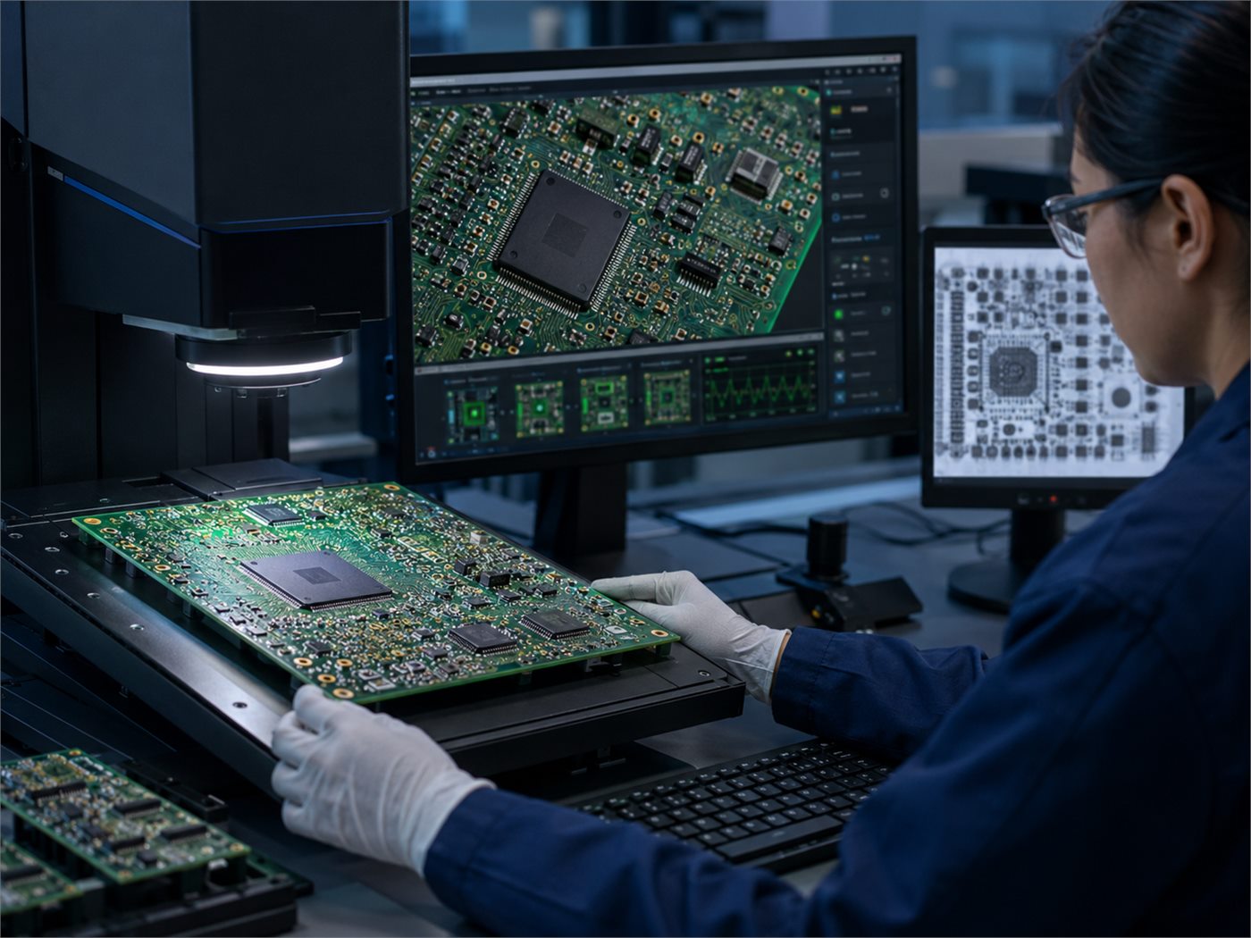
IPC Class 3 PCB assembly inspection using automated optical inspection and X-ray review

Common verification methods include:

  • Electrical testing: Confirms continuity and isolation.
  • Microsection analysis: Checks plated holes, internal connections, copper thickness, and dielectric spacing.
  • Impedance testing: Verifies controlled-impedance coupons.
  • AOI: Finds conductor, component-placement, and soldering defects.
  • X-ray inspection: Examines hidden solder joints.
  • Cleanliness testing: Evaluates ionic contamination when specified.
  • ICT or functional testing: Verifies assembled-board operation.

Customers should state which records must be delivered:

  • Certificate of conformity
  • Material certificate
  • Electrical test record
  • Impedance report
  • Microsection report
  • First-article report
  • AOI or X-ray record
  • Lot traceability
  • Rework history

A manufacturer may perform internal testing without automatically supplying the complete report package.

IPC Class 3 Examples and Typical Applications

Class 3 is generally selected when failure has a serious operational, financial, or safety consequence.

Typical applications include:

  • Flight-control and navigation electronics
  • Defense communication equipment
  • Space and satellite systems
  • Life-support and selected implantable medical devices
  • Railway signaling and braking controls
  • Industrial emergency shutdown systems
  • Remote equipment that is difficult to service
  • Critical battery and power-control systems

Not every product in these sectors needs Class 3. A cabin entertainment controller is not equivalent to a flight-control module. A consumer medical wearable is not equivalent to an implantable device.

Some projects also require an industry-specific IPC addendum or customer specification. These requirements should be identified before quotation.

When Should You Choose IPC Class 2 or Class 3?

Choose Class 3 when the risk justifies the extra controls.

Class 3 is usually appropriate when:

  • Failure could create a safety hazard.
  • Continuous operation is mandatory.
  • Field replacement is difficult or expensive.
  • The product faces severe vibration or thermal cycling.
  • Detailed traceability is required.
  • The contract names Class 3.
  • Qualification requires structural test evidence.

Class 2 may be more practical when:

  • The product has a normal commercial or industrial duty cycle.
  • Repair or replacement is accessible.
  • Failure does not interrupt a critical function.
  • The PCB would need substantial redesign for Class 3 margins.
  • The additional cost does not reduce a meaningful product risk.

A customer can also request targeted reliability controls without claiming full Class 3 compliance. Examples include tighter hole tolerances, 100% electrical testing, X-ray inspection, impedance reports, or material traceability.

This can be cost-effective, but the product should not be described as Class 3 unless all applicable Class 3 requirements are met.

IPC Class 3 PCB Order and RFQ Checklist

A clear RFQ package prevents assumptions and quotation revisions.
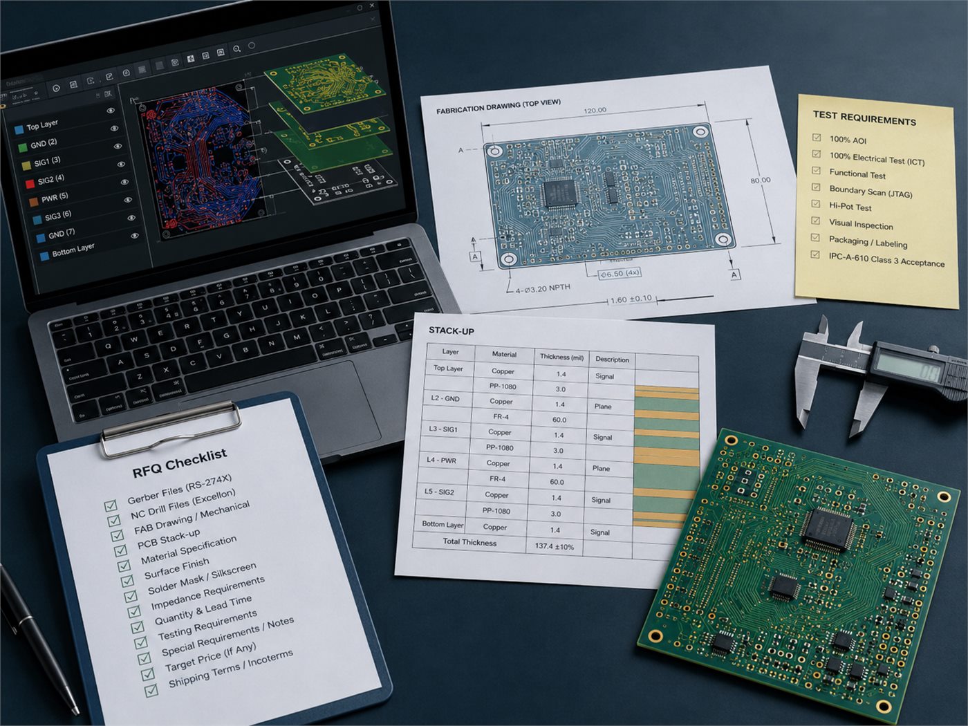
IPC Class 3 PCB RFQ checklist with fabrication drawing, stack-up, Gerber data, test requirements, and PCB sample

Provide:

  • Gerber, ODB++, or IPC-2581 files
  • NC drill files
  • Fabrication drawing
  • Approved stack-up
  • Applicable IPC standards and revisions
  • Required product class
  • Laminate and material requirements
  • Finished board and copper thickness
  • Finished-hole sizes and tolerances
  • Blind, buried, microvia, fill, and cap requirements
  • Controlled-impedance targets
  • Surface finish
  • Electrical testing requirements
  • Coupon and microsection requirements
  • Material and test reports
  • Serialization and traceability rules
  • Repair restrictions
  • Assembly acceptance class
  • AOI, X-ray, ICT, or functional-test requirements
  • Packing and labeling instructions

Critical requirements should appear on the fabrication drawing rather than only in an email.

At EBest Circuit, we can review stack-up feasibility, annular-ring margin, drill-to-copper clearance, HDI structures, material availability, inspection documents, and test requirements. This helps distinguish necessary Class 3 controls from optional items that add cost without addressing the main product risk.

FAQs About IPC Class 3

Is IPC Class 3 the highest PCB quality class?Class 3 is the highest of the three general IPC product classes, but additional sector-specific requirements may apply. Aerospace, military, space, medical, and automotive projects may reference an applicable addendum or customer specification beyond the base Class 3 criteria.

What is the definition of a J-STD-001 Class 3 product?It is a high-performance electronic assembly manufactured using the Class 3 process and workmanship requirements of J-STD-001. The product is expected to remain dependable when continuous operation or performance on demand is critical.

Is IPC Class 3 the same as IPC-6012 Class 3?No. IPC Class 3 is a product-performance classification used across several IPC documents. IPC-6012 Class 3 specifically applies to the qualification and performance of rigid bare PCBs.

A completed PCBA may also need J-STD-001 Class 3 and IPC-A-610 Class 3 requirements.

What is the difference between IPC Class 2 and Class 3?Class 3 uses tighter acceptance requirements and generally demands more manufacturing margin, process control, structural verification, inspection, traceability, and documentation. Class 2 focuses on continued service for commercial and industrial products where failure is undesirable but not normally critical.

Does IPC Class 3 specify a minimum via size?There is no single minimum via diameter for every Class 3 PCB. Via size must be selected according to the finished board thickness, aspect ratio, drilling method, plating capability, annular ring, registration, and reliability requirement.

Can a Class 2 PCB design be manufactured to Class 3?Sometimes, but not automatically. The design must first be checked for annular-ring margin, drill-to-copper clearance, dielectric spacing, conductor geometry, via structure, documentation, and testability. A tightly packed Class 2 layout may require pad or clearance changes before it can reliably meet Class 3 acceptance.

Is IPC Class 3 required for all medical PCBs?No. The requirement depends on the device function, failure risk, regulatory strategy, customer specification, and applicable product standard. A critical implantable or life-support product may need Class 3 plus a medical addendum, while a non-critical accessory may use Class 2.

Is IPC Class 3 required for automotive electronics?Not for every automotive PCB. Safety-related systems may require demanding reliability controls, but the applicable requirements should come from the customer specification, automotive qualification plan, IPC addendum, and other automotive standards.

What is IPC Class 3/A?Class 3/A is commonly used to describe Class 3 products with additional aerospace or military avionics requirements. It should not be treated as a universal fourth IPC class. The applicable base standard, addendum, revision, and customer specification must be stated.

Where can I obtain an IPC Class 3 PDF?Official IPC standards are copyrighted documents and should be obtained through IPC’s authorized channels. A manufacturer-created IPC Class 3 checklist may summarize design and RFQ considerations, but it does not replace the official standard.

Conclusion

IPC Class 3 is appropriate when product risk, operating conditions, or contractual requirements justify tighter design margins, stronger process controls, additional inspection, and detailed traceability.

It should be specified before PCB layout release. Buyers should clearly identify the applicable standards, revision levels, testing, documentation, and assembly criteria.

Request an IPC Class 3 PCB or PCBA Review

Send your files, stack-up, quantity, standards, testing requirements, and reporting needs to sales@bestpcbs.com. EBest Circuit can evaluate the manufacturing risks and prepare a quotation based on the actual reliability requirements of your project.


You may also like

Industrial PCB manufacturing services with 24-hour prototyping, 10-year reliability
Thursday, December 4th, 2025

Industrial PCB manufacturing is the backbone of mission-critical electronic systems in aerospace, automotive, industrial automation, and medical devices. Unlike commercial PCBs designed for consumer-grade use, industrial-grade printed circuit boards are engineered to withstand extreme conditions—including wide temperature ranges (-40°C to 125°C), continuous operation for a decade or more, and high mechanical stress from vibration or shock. With 20 years of expertise, our industrial PCB manufacturing services deliver unmatched durability, precision, and reliability, making us the trusted partner for 300+ leading enterprises (including 20 Fortune 500 companies) in high-stakes applications.

Industrial PCB manufacturing services with 24-hour prototyping, 10-year reliabilityhttps://www.bestpcbs.com/blog/2025/12/industrial-pcb-manufacturing/

Why Choose Our Industrial PCB Manufacturing Services? 5 Core Advantages

Selecting the right industrial PCB manufacturing partner is critical to avoiding costly downtime, quality issues, and project delays. Our 20-year track record speaks for itself with these industry-leading benefits:

  • Exceptional Quality: 99.9% defect-free rate (industry average 85%), 10-year trouble-free operation guarantee, and failure rate below 3PPM (parts per million)
  • Technical Expertise: 50+ senior engineers specializing in HDI, rigid-flex, high-temperature, high-frequency, and high-power industrial PCB manufacturing, with 10,000+ complex projects completed
  • Rapid Response: Dedicated account managers available 24/7, 1-hour consultation response, and DFM (Design for Manufacturability) reports within 4 hours
  • Transparent Pricing: Direct supplier pricing with up to 40% bulk discounts, clear pricing for special processes (impedance control, edge plating), and no hidden fees
  • On-Time Delivery: 98% of orders shipped on time or early, emergency prototyping in as fast as 24 hours, and zero major delivery incidents in 10 years

Industrial PCB Manufacturing Solutions for 3 Key Industry Pain Points

Our industrial PCB manufacturing services are tailored to solve the most pressing challenges faced by engineers and procurement teams:

Tight Deadlines? IPC Class 3 certified production with 24-hour prototyping for 1-4 layer boards, 48-hour delivery for multi-layer PCBs, and 7-day accelerated mass production—3x faster than industry averages

Quality Concerns? Premium materials including high-Tg FR4 (135°C+), ceramic, and polyimide substrates; copper thickness ≄2oz; 10,000-cycle connector durability; and 4-stage testing (AOI, X-ray, thermal cycling, vibration)

Cost Overruns? Free DFM optimization (reducing production costs by 15% on average), tiered bulk pricing, no minimum order quantity (start with 10 units), and lifetime valid quotes with no price hikes

Whether you need small-batch prototyping, medium-volume pilot runs, or large-scale production, our engineering team provides end-to-end support from design review to delivery, helping clients shorten time-to-market by 30% and reduce overall costs by 20%.

Key Requirements for High-Performance Industrial PCB Manufacturing

The difference between commercial and industrial PCB manufacturing lies in reliability under extreme conditions. We understand that a single PCB failure can cause million-dollar losses, production downtime, or safety hazards—so our industrial-grade PCBs meet these strict criteria:

  • Wide temperature tolerance: Stable operation from -40°C to 125°C (covering polar, desert, and high-temperature workshop environments)
  • Long service life: 10+ years of continuous use (vs. 2-5 years for consumer-grade PCBs) with <0.1% annual aging rate
  • Harsh environment resistance: Waterproof, dustproof, chemical corrosion resistance, and 48-hour salt spray test pass
  • Mechanical durability: Vibration resistance (10-2000Hz), shock resistance (50G), and suitability for high-frequency movement in automotive, aerospace, and industrial equipment

These standards are backed by meticulous attention to detail: our specialty substrates cost 60% more than standard materials, copper etching tolerance is controlled to ±0.1mm (industry average ±0.3mm), and plating thickness is ≄30ÎŒm—ensuring each PCB is a reliable component of critical systems.

4 Core Materials for Industrial PCB Manufacturing

Material selection is critical to industrial PCB manufacturing performance. We partner directly with the world’s top 3 substrate suppliers to ensure consistent quality:

High-Tg FR4 Substrates (60% Application Rate)

  • Thermal stability: 135°C+
  • Ideal for: Industrial control, power electronics, automotive electronics
  • Advantages: Best cost-performance ratio, 30% bulk pricing discount, fastest delivery time

Metal Core PCBs (High-Power Applications)

  • Thermal conductivity: 10x higher than standard FR4
  • Ideal for: LED modules, motor controllers, inverters
  • Advantages: 40% lower heat dissipation costs, 2x longer service life

Ceramic Substrates (High-Frequency/High-Temperature)

  • Materials: Aluminum nitride (AlN), aluminum oxide (Al2O3)
  • Ideal for: Aerospace, RF communication, laser equipment
  • Advantages: 200°C maximum operating temperature, <5% signal transmission loss

Polyimide Substrates (Extreme Environments)

  • Temperature range: -269°C to 280°C
  • Ideal for: Downhole drilling, military, medical implants
  • Advantages: <0.05% annual aging rate, military-grade reliability certification

6 Critical Processes in Our Industrial PCB Manufacturing

We’ve developed an internal quality control system exceeding IPC standards, with 6 rigorous processes for every industrial PCB manufacturing project:

  1. DFM Intelligent Review: AI + manual double-check to identify design flaws (e.g., insufficient line width, hole misalignment), with optimization plans within 4 hours—reducing prototyping failure rate by 90%
  2. High-Precision Lamination: Imported pressing equipment with ±0.1mm copper etching tolerance and ±0.05mm layer alignment accuracy to avoid signal interference
  3. Bubble-Free Pressing: Precise temperature (±1°C) and pressure (±0.1MPa) control, with layer peel strength ≄1.5N/mm to prevent delamination
  4. Laser Micro-Drilling: Minimum hole size 0.1mm, 99.8% yield for blind/buried holes, suitable for HDI (High-Density Interconnect) designs
  5. Eco-Friendly Plating: ENIG (Electroless Nickel Immersion Gold) or immersion tin processes with uniform plating thickness (±2Όm) for corrosion resistance and easy soldering
  6. Comprehensive Testing: AOI optical inspection → X-ray internal structure testing → electrical continuity testing → thermal cycling (-40°C~125°C, 50 cycles) → vibration testing → sampling aging testing

Industrial PCB Manufacturing vs. Commercial PCB Production: Key Differences

Comparison FactorOur Industrial PCB ManufacturingCommercial PCB Production
Quality StandardIPC Class 3 (Highest Level) + Internal Military-Grade StandardsIPC Class 1-2 (Consumer-Grade)
Service Life10+ Years (Including Warranty)2-5 Years (No Long-Term Warranty)
Temperature Range-40°C ~ 125°C (Wide Temperature Adaptation)0°C ~ 70°C (Room Temperature Only)
Material QualityHigh-Tg FR4/Ceramic/Polyimide (Imported Substrates)Standard FR4 (Low-Cost Domestic Substrates)
Testing Process6-Stage Comprehensive Testing (Including Aging/Vibration)Visual Inspection Only
Defect Rate≀3PPM15,000PPM (1.5%)
Warranty Service10-Year Trouble-Free Warranty + Lifetime Technical Support1-Year Warranty + Limited Support

Core Industries for Our Industrial PCB Manufacturing Services

Our industrial PCB manufacturing expertise spans diverse high-demand sectors, with proven success in:

  • Automotive: EV powertrains (supplier to BYD/NIO), ADAS (Advanced Driver Assistance Systems), and automotive extreme environment adaptation
  • Aerospace: Satellite communication equipment, avionics (supporting COMAC), radiation resistance, and high-voltage testing compliance
  • Industrial Automation: PLCs (Programmable Logic Controllers), sensor modules (partner with Siemens/Schneider), and high-frequency start-stop support
  • Medical Devices: Diagnostic equipment, implantable devices (ISO 13485 certified), and biocompatibility + reliability compliance
  • Energy: Solar inverters, wind turbine control systems (partner with Huawei/Sungrow), and outdoor harsh environment adaptation

FAQ About Industrial PCB Manufacturing

Can You Handle Small-Batch Orders (10-100 Units)? What’s the Lead Time?

Yes! We have no minimum order quantity—start with 10 units. 1-4 layer PCBs are delivered in 24 hours, multi-layer PCBs in 48 hours, 3x faster than industry standards. Small-batch quality matches large-scale production.

Which Material Is Best for High-Temperature/High-Frequency/High-Power Applications?

– High-temperature (105°C+): Polyimide or ceramic substrates
– High-frequency (2GHz+): PTFE substrates
– High-power (≄50W): Metal core PCBs
We offer free material selection consulting for your specific application.

Can You Support Unprofessional Design Schemes?

Absolutely! Our free DFM design review service provides optimization reports within 4 hours of receiving Gerber files—including manufacturability improvements, cost reduction suggestions, and reliability enhancements. Perfect for both new and experienced engineers.

What If There’s a Quality Issue?

We stand behind our industrial PCB manufacturing with a 10-year trouble-free warranty. For non-human quality issues, we ship replacement products within 48 hours. For critical projects, we provide backup inventory to ensure zero production downtime.

What Industry Certifications Do You Hold?

All products are certified to IPC-A-600 Class 3, ISO 9001, ISO 14001, and UL 796. Automotive products meet IPC-6012/TS 16949; medical products meet ISO 13485; and aerospace products meet AS9100. Certification reports are available upon request.

Start Your Industrial PCB Manufacturing Project Today

Our production capacity and technical resources are prioritized for high-demand industrial PCB manufacturing clients. Take action now to:

  • Get a free copy of the “Industrial PCB Manufacturing Selection Guide” + custom DFM review
  • Access our 24-hour emergency delivery channel—contact your account manager to lock in capacity

Submit your design files and project requirements, and we’ll provide: ① Accurate quotation ② DFM optimization report ⑱ Production timeline ④ Warranty plan—all within 24 hours. With 20 years of focus, we make industrial PCB manufacturing risk-free, efficient, and cost-effective—helping you launch projects faster and gain market advantage.

You may also like