How to read a circuit diagram schematic begins with one principle: a schematic shows electrical relationships, not the physical positions of parts on a PCB. Start by identifying the power source and ground, divide the drawing into functional blocks, follow named nets and signal paths, and then verify component references, values, pin numbers, and page connections. This method works more reliably than trying to read every line from the upper-left corner to the lower-right corner.
What Does a Circuit Diagram Schematic Show?
A circuit diagram schematic shows which component pins are electrically connected and how power, signals, and control functions move through a design. Symbols stand for components, lines and labels identify electrical nets, and reference designators link each symbol to controlled design data.
The drawing is logical rather than physical. Two symbols placed next to each other may be far apart on the finished board. Two points on different pages may be electrically connected by the same net label. A schematic also does not define trace width, copper layer, via structure, component rotation, or exact placement unless that information is added separately.
This distinction prevents a common error: treating the schematic as a map of the PCB. The schematic explains what must connect and why. The PCB layout determines where components, pads, copper traces, planes, and vias are physically implemented.
How Do You Read Schematics Step by Step?
Read schematics by moving from overall purpose to individual connections. The following sequence keeps a complex page manageable:
- Confirm the drawing type. Determine whether the file is an electronic schematic, wiring diagram, block diagram, or PCB layout.
- Read the title block and notes. Check the sheet name, revision, page references, voltage domains, and drawing conventions.
- Locate power entry and ground. Identify input connectors, protection, regulation, power rails, and return references.
- Divide the design into functional blocks. Typical blocks include input protection, power conversion, sensors, analog conditioning, processing, communications, and output drivers.
- Choose one signal path. Follow it from its source through each stage to its destination rather than jumping between unrelated nets.
- Read symbols together with their fields. Check reference designators, values, part numbers, pin names, and polarity.
- Follow named nets and page links. A label can connect distant points without a continuous drawn wire.
- Cross-check supporting files. Compare the schematic with the BOM, datasheets, PCB layout, and assembly information.
Repeat the process for each power rail, interface, and functional signal. A first pass establishes structure; later passes resolve component-level behavior.
Which Circuit Symbols Should You Recognize First?
Begin with the symbols that appear in nearly every electronic schematic: power sources, ground, resistors, capacitors, inductors, diodes, transistors, integrated circuits, connectors, switches, and test points. You do not need to memorize every device variant before reading a basic circuit.
| Symbol group | What it tells you | What still needs verification |
|---|---|---|
| Power and ground | Supply rails, references, returns, chassis, or earth connections | Voltage, current limit, sequencing, and whether grounds are intentionally separated |
| R, C, and L | Resistance, capacitance, inductance, filtering, timing, biasing, or energy storage | Value, tolerance, rating, package, and frequency behavior |
| Diodes and transistors | Polarity, switching, rectification, clamping, amplification, or drive functions | Exact device, pinout, voltage, current, and thermal limits |
| IC blocks | Functional pins and logical relationships | Datasheet pin functions, supply pins, package mapping, and unused-pin requirements |
| Connectors | Signals entering or leaving the circuit | Pin numbering, mating view, cable orientation, and external voltage levels |
Symbol appearance can vary between IEC and ANSI/IEEE conventions. The existing electrical symbols and electronic symbols chart covers these variants in more detail. Always interpret a symbol with its designator and surrounding circuit rather than by shape alone.
How Do Reference Designators, Values, and Pin Numbers Work?
A reference designator identifies one specific component instance. The letter indicates the component class and the number distinguishes it from other parts of the same class. Common examples include R for resistor, C for capacitor, L for inductor, D for diode, Q for transistor, U for integrated circuit, J for connector, and TP for test point.
The nearby value field explains what that instance is. `R12 10 kΩ` identifies a particular 10-kilohm resistor; `C7 100 nF` identifies a particular capacitor. An IC may show a device name instead of a simple numeric value. Do not assume the field contains every required rating. Voltage rating, tolerance, dielectric, package, manufacturer part number, and approved alternatives may reside in the BOM or component database.
Pin names describe function, while pin numbers connect the logical symbol to the physical package. An IC symbol may group power pins, analog pins, and digital pins for readability, so the displayed order often differs from the package’s clockwise pin order. Verify the symbol-to-footprint pin mapping against the datasheet before using the schematic to diagnose or manufacture a board.
How Do Wires, Junctions, Nets, and Labels Work?
A net is a set of electrically connected pins and conductors. A drawn line normally indicates a connection, while a junction dot marks multiple lines that share the same node. Crossing lines without a dot usually do not connect, although older drawing conventions may use a bridge or other notation. Check the drawing legend when the convention is unclear.
Net labels connect points by name. Every point labeled `3V3` belongs to the same 3.3 V network unless the design tool or hierarchy defines a narrower scope. Labels such as `SCL`, `SDA`, `RESET`, `USB_D+`, or `MOTOR_EN` are often more useful than the visual line because they state the signal’s role.
Hierarchical labels and off-page connectors move signals between sheets. A continuation marker should provide a page, block, port, or net name that can be followed. When a line seems to end without explanation, look for a label before assuming the circuit is incomplete.
How Should You Find Power and Ground?
Start at the power connector, battery, USB input, or other supply source. Follow the path through fuses, reverse-polarity protection, transient suppressors, filters, regulators, and current-sense elements. Record each resulting rail, such as 12 V, 5 V, 3.3 V, 1.8 V, or an isolated supply.
Next, identify the ground references. A design may contain digital ground, analog ground, power ground, chassis ground, protective earth, or an isolated secondary return. They are not automatically interchangeable. Look for explicit connection points, net ties, ferrites, resistors, capacitors, or isolation barriers that define how the references relate.
Power symbols can hide long connections and may also hide IC supply pins in some libraries. Check the component unit and datasheet if an IC appears to have no power pins. A signal can only be interpreted correctly after its voltage domain and reference are known.
How Do You Trace Signal Flow Through a Schematic?
Choose one input and follow it through each functional stage. A sensor signal, for example, may pass through protection, filtering, biasing, amplification, analog-to-digital conversion, digital processing, and an output driver. Read one chain completely before moving to another.
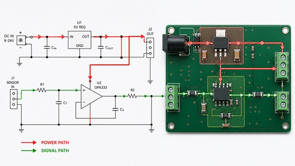
Signal flow is not always left to right. Feedback paths return from an output to an earlier stage; bidirectional buses carry information both ways; differential pairs use two complementary nets; and power-control signals may cross several voltage domains. Arrows, pin names, datasheet block diagrams, and interface standards help determine direction.
At each stage, ask what changes: voltage level, current capability, frequency content, logic state, impedance, or isolation. This turns a line-following exercise into an explanation of circuit behavior.
How Do You Divide a Complex Schematic into Functional Blocks?
Functional blocks reduce a large schematic into smaller circuits with clear inputs and outputs. Begin with obvious anchors such as connectors, regulators, microcontrollers, communication transceivers, sensors, and power switches. Then group the surrounding passive components according to the device they support.
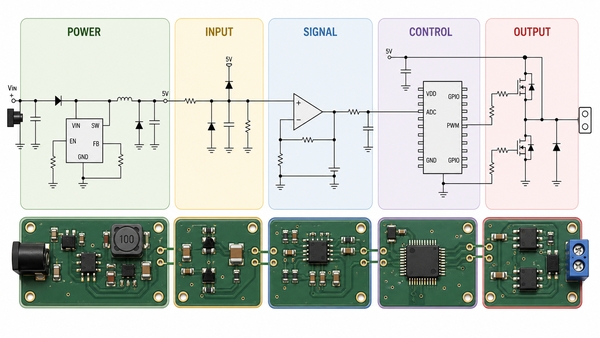
A practical block sequence might be:
- power entry, protection, conversion, and distribution;
- external inputs and interface protection;
- analog filtering, sensing, or amplification;
- processor, memory, clock, and reset;
- communications and level translation;
- output drivers, loads, and connectors.
After identifying the blocks, trace the nets that cross their boundaries. These interfaces reveal the system architecture more quickly than reading every local bypass capacitor or pull resistor first.
How Do You Read Multi-Sheet and Hierarchical Schematics?
Multi-sheet designs use hierarchy to prevent one page from becoming unreadable. A top sheet may show major blocks as sheet symbols, while lower-level sheets contain their detailed circuits. Ports on the parent sheet must correspond to hierarchical labels on the child sheet.
Use the sheet index, page references, and net names as navigation tools. Global labels may connect all sheets, while local labels may apply only inside one sheet or hierarchy level. The exact scope depends on the EDA system and project settings.
Also check repeated channels. One amplifier or sensor block may be instantiated several times with different reference designators. Confirm which channel you are tracing and whether shared power, reference, or control nets affect every instance.
How Is a Schematic Different from a Wiring Diagram and PCB Layout?
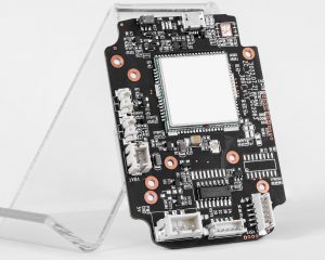
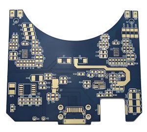
A schematic emphasizes electrical function. A wiring diagram emphasizes physical terminals, wire colors, harness routes, and installation connections. A PCB layout implements the schematic as footprints, placement, copper, vias, planes, mechanical outlines, and fabrication layers.
| Document | Main question answered | Typical information |
|---|---|---|
| Schematic | What is electrically connected and how should the circuit work? | Symbols, pins, nets, values, labels, and functional relationships |
| Wiring diagram | How are physical devices or terminals wired together? | Wire numbers, colors, connectors, terminal blocks, routes, and harness details |
| PCB layout | How is the electronic circuit physically built on the board? | Footprints, placement, traces, vias, planes, stack-up, and mechanical constraints |
Use the correct document for the task. A schematic can reveal that two pins share a net, but it cannot show whether a copper trace is damaged. A PCB layout can show where the trace runs, but it may not explain the intended signal behavior as clearly as the schematic.
How Do You Read a Simple LED Circuit Step by Step?
Consider a DC source connected to a current-limiting resistor, an LED, and ground. First identify the supply voltage and its return. Next check LED polarity: conventional current enters the anode and leaves the cathode. Then read the resistor value and verify that it limits current to an appropriate level for the selected LED and supply.
Trace the closed path: positive supply → resistor → LED → ground or negative return. If a transistor controls the LED, separate the load path from the control path. The transistor may switch LED current while a GPIO drives its base or gate through another resistor. A pull-down or pull-up sets a known state when the controller output is inactive.
This example demonstrates the full method on a small circuit: identify power, recognize symbols, read values and polarity, trace the active path, and distinguish control from load current.
Which Schematic Reading Mistakes Can Cause PCB Problems?
The most consequential errors are usually connection or mapping errors rather than unfamiliar symbols.
- Missing a junction: a connected node is treated as two separate nets, or crossing lines are incorrectly joined.
- Ignoring polarity: a diode, LED, electrolytic capacitor, or polarized connector is interpreted backward.
- Confusing pin names and numbers: the logical function is assigned to the wrong package pad.
- Overlooking global labels: distant points on the same rail are treated as unrelated.
- Assuming ground symbols are identical: isolated, chassis, analog, and power returns are joined incorrectly.
- Reading the symbol without the datasheet: device-specific pin behavior, ratings, or unused-pin rules are missed.
- Assuming schematic position equals PCB position: troubleshooting begins in the wrong physical area.
Each interpretation should be checked against the design revision being used. A correct reading of an obsolete schematic can still lead to an incorrect conclusion about the current board.
How Do You Compare a Schematic with the BOM and PCB Layout?
Use the reference designator as the common key. The schematic identifies the function and connections of `U1`; the BOM identifies its approved part and package; the PCB layout identifies its physical footprint, orientation, and copper connections.
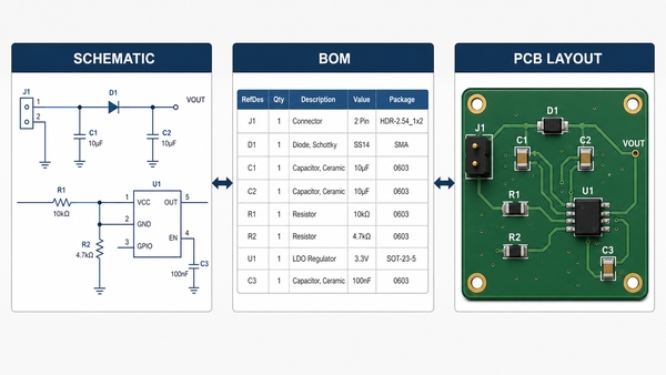
Check that every populated schematic reference has a corresponding BOM entry and footprint. Verify that symbol pin numbers match footprint pad numbers. Confirm polarized footprints, connector views, pin 1 markers, and multi-unit components. For net checks, select a schematic net and verify that the same net connects the intended pads in the layout.
This cross-check is especially important before PCB assembly, because the schematic, BOM, placement data, and board layout must describe the same revision. EBest Circuit (Best Technology) uses engineering review to identify inconsistent component references, polarity information, footprint assignments, and production data before assembly begins.
FAQ About Reading Circuit Diagram Schematics
Can ChatGPT read electrical schematics?
AI can help identify common symbols, summarize functional blocks, and explain likely signal paths when the schematic is clear. It can still misread small labels, junction dots, pin numbers, or device-specific behavior. Verify every conclusion against the original high-resolution drawing, datasheets, netlist, and controlled design files.
How hard is it to read schematics?
Basic schematics become manageable after learning common symbols, nets, designators, power references, and a consistent reading sequence. Complex mixed-signal, RF, power, or multi-sheet designs require more circuit knowledge and careful datasheet review.
Do you read every schematic from left to right?
No. Many schematics are arranged approximately from input to output, but feedback, power distribution, buses, and hierarchical connections break that pattern. Start with functional blocks and follow one named path at a time.
What does a dot on crossing schematic lines mean?
A dot normally indicates an electrical junction. Crossing lines without a dot normally do not connect, but older drawings may use different conventions. Check the legend and nearby examples before deciding.
Why do IC pins appear out of numerical order?
Schematic symbols often group pins by function to improve readability. The physical package still follows its numbered pad arrangement, so the symbol pin numbers must be checked against the datasheet and footprint.
What should you check first on an unfamiliar schematic?
Check the title, revision, sheet structure, power inputs, ground references, main connectors, and major ICs. These elements reveal the circuit’s purpose and provide stable starting points for tracing individual signals.
Conclusion
How to read a circuit diagram schematic becomes much easier when the drawing is treated as a network of functional blocks rather than a page of unrelated symbols. Find power and ground, follow one signal path at a time, use net labels and page references, and verify every designator, value, pin, and footprint against the supporting files.
EBest Circuit (Best Technology) supports PCB fabrication and PCBA assembly with engineering review of schematics, BOMs, Gerber or ODB++ data, component placement, polarity, footprints, and manufacturing consistency. For PCB or PCBA support, contact sales@bestpcbs.com.