An engine monitor collects operating data and turns it into readable information about engine temperature, speed, pressure and other parameters. Depending on the application, it may receive signals directly from sensors or read data from an electronic control unit (ECU). Behind the display, the quality of the measurement electronics, power supply and assembled circuit board affects how consistently that information reaches the user.
At EBest Circuit, we combine PCB fabrication, component sourcing and SMT/THT assembly to support electronic product development. For engine-monitor hardware, our DFM reviews can address manufacturable routing, connector footprints and assembly access before a prototype build. Discuss your project through Contact Us, scroll to the bottom of the page and complete the contact form, or email sales@bestpcbs.com.
What Is an Engine Monitor?
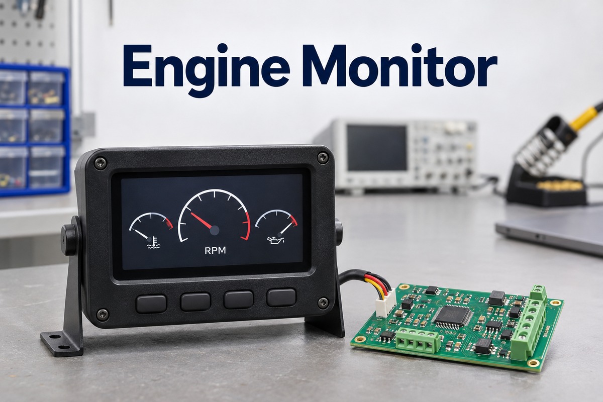
An engine monitor is an electronic system that acquires engine data, displays operating values and generates configured warnings. Its PCB assemblies may handle direct sensor inputs, ECU communication, display control or a combination of these functions.
The hardware can be divided into three functional blocks.
- Acquisition board. Receives temperature, pressure, fuel-level and RPM signals. For scale, the EDC-33P used with the CGR-30P has 17 temperature channels, 6 pressure channels and 2 RPM channels, alongside other inputs. These are channel capacities, not the number of readings shown simultaneously.
- Processor and interface board. Converts measurements into engineering units, decodes network messages and manages alarms or stored data. This function can share a PCB with the acquisition circuitry.
- Display board. Drives the screen, backlight and user controls. The display may be integrated into the monitor or connected to a separate acquisition module.
Suitable PCB constructions depend on the circuit and enclosure.
- Two-layer rigid FR-4 PCB. A candidate for a simple, low-channel-count interface or indicator with modest routing demands. Noise performance and return paths still require validation.
- Four- or six-layer rigid FR-4 PCB. A practical design option for mixed-signal acquisition, MCU, memory and bus-interface circuitry when reference planes and additional routing layers are needed. This is a design recommendation, not a universal engine-monitor layer count.
- FPC or rigid-flex PCB. Suitable where a compact enclosure needs a flexible connection between the main board and display. Dynamic flexing requires a dedicated bend design; vibration alone does not justify rigid-flex.
- High-Tg FR-4 PCB. An option where the assembly process and thermal requirements justify that laminate grade. Tg does not define the instrument’s permissible ambient temperature.
For the main acquisition and control electronics, rigid FR-4 is a practical starting point. Metal-core or ceramic boards are more relevant to separate circuits with significant heat-dissipation needs than to low-power sensor inputs.
What Parameters Does an Engine Monitoring System Measure?
An engine monitoring system measures the parameters supported by its sensors, interfaces and software. Common groups include rotational speed, temperatures, pressures, fuel information and electrical supply conditions.
- Engine speed. RPM may come from a tachometer signal, a speed sensor or an ECU message.
- Temperature. Depending on the engine, useful measurements include coolant, oil, exhaust gas and cylinder head temperatures.
- Pressure. Oil pressure, fuel pressure and intake manifold pressure describe different parts of engine operation.
- Fuel information. Fuel flow, tank level and calculated consumption are separate values. A flow measurement does not directly establish the amount of fuel remaining in a tank.
- Electrical condition. Supply voltage and, where supported, current help show the operating state of the electrical system.
Not every value on a display is measured directly. Fuel economy may be calculated from fuel consumption and distance, while estimated fuel remaining may depend on an initial fuel entry. The reliability of a calculated value therefore depends on both its inputs and its configuration.
An OBD-II connection does not guarantee access to every desired parameter. Availability depends on the vehicle, supported data identifiers and the monitor’s compatibility. Additional sensors may be necessary for measurements that the ECU does not provide.
How Does a Digital Engine Monitor Work?
A digital engine monitor follows a signal chain of acquisition, conversion, processing and output. Direct sensor inputs require measurement circuitry; ECU data inputs require compatible message decoding.
1. Acquire and condition the input.
A thermocouple produces a small voltage, a resistive sender changes resistance, and a tachometer input supplies pulses. Each needs an appropriate input circuit. As a commercial example, the Actisense EMU-1 accepts tachometer frequencies from 4 to 30,000 Hz. That is an electrical input range, not an engine-speed range in RPM.
For a pulse-based measurement, RPM = frequency × 60 ÷ pulses per revolution. With an assumed 2 pulses per revolution, a 100 Hz signal represents 3,000 RPM. An incorrect pulse configuration therefore produces an incorrect speed even when the pulse counter works correctly.
2. Convert analog signals into digital values.
The TI ADS1118 illustrates the capabilities of a measurement ADC suitable for thermocouple circuitry. It provides 16-bit conversion, 4 single-ended or 2 differential inputs, and selectable conversion rates from 8 to 860 samples per second. Its inputs are multiplexed, so the maximum rate is not available simultaneously on every channel.
At the ±0.256 V range, its ideal code step is 7.8125 µV. This describes voltage resolution, not total temperature accuracy; sensor error, noise and cold-junction compensation also contribute.
3. Apply scaling and calibration.
Firmware converts ADC codes or decoded messages into values such as °C, bar and RPM. Consider an illustrative pressure sensor specified as 0.5–4.5 V for 0–10 bar. Its 4 V span corresponds to 10 bar, so 2.5 V represents 5 bar under the assumed linear transfer function. The PCB input circuit must accommodate that voltage range, and the firmware must use the correct sensor characteristic.
4. Display, warn and record.
Sampling rate, screen refresh and logging rate serve different purposes. For example, the CGR-30P records monitored functions up to 3 times per second and stores up to 1,500 flights. These are product logging specifications, not ADC conversion rates. A faster ADC alone does not establish how quickly the complete instrument updates or records its readings.
How Do Aircraft Engine Monitors Track EGT and CHT?
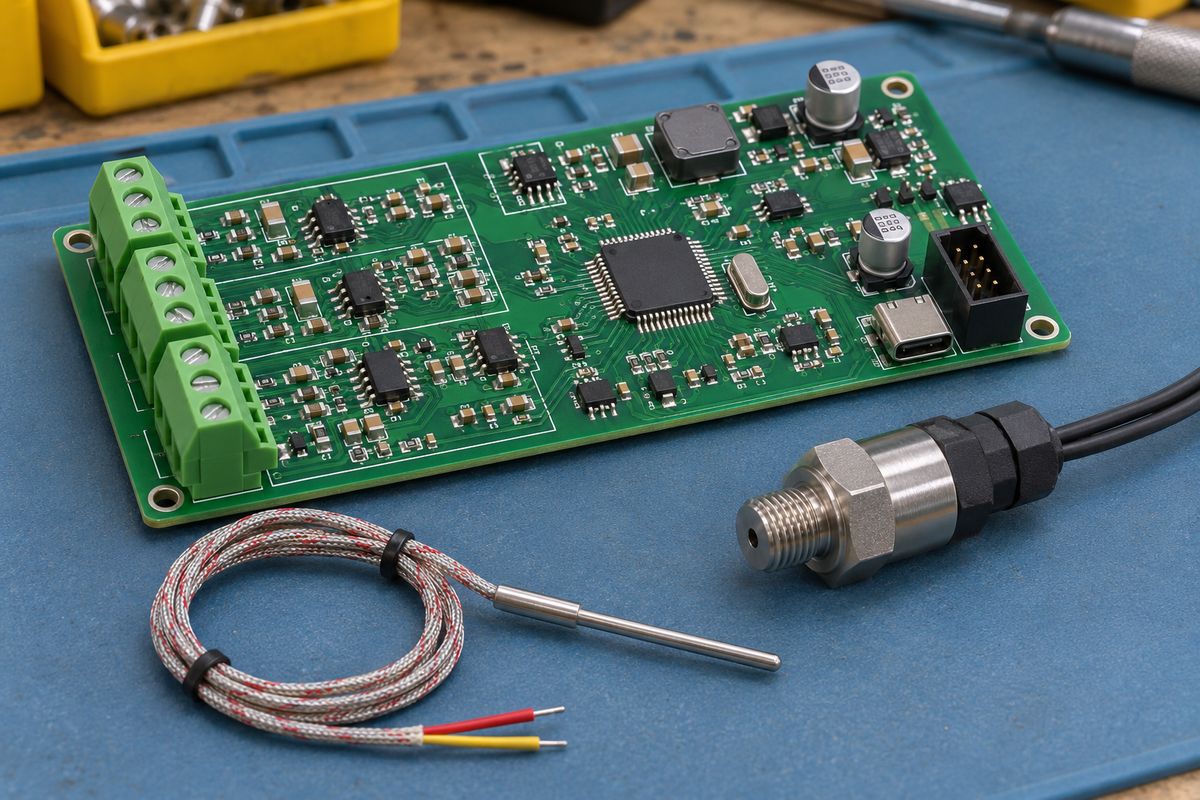
Aircraft engine monitors commonly use individual probes to track exhaust gas temperature (EGT) and cylinder head temperature (CHT) on piston engines. Displaying channels together helps reveal differences between cylinders and changes over time.
EGT describes exhaust-gas temperature near the probe location. It responds to combustion conditions and is used in supported systems to assist mixture adjustment. Absolute readings also depend on probe placement, so comparisons require context.
CHT describes cylinder-head temperature at the sensor location. It reflects the thermal condition of the cylinder head and generally changes more slowly than exhaust-gas temperature. EGT and CHT therefore provide complementary information rather than interchangeable measurements.
For thermocouple inputs, the electronics measure a small voltage related to the temperature difference between the sensing junction and the reference junction. Cold-junction compensation accounts for the reference-junction temperature. Keeping the reference sensor thermally representative of the connector region helps avoid errors caused by nearby heat sources.
This creates a direct PCB-layout concern. Regulators, processors and display circuitry can heat the input area unevenly, while switching noise can interfere with low-level signals. Thermal placement and electrical layout both affect measurement quality.
Operating limits and mixture procedures remain specific to the engine and aircraft. A monitor supports observation; its readings do not replace the applicable operating instructions.
How Do Automotive, Diesel and Marine Engine Monitoring Systems Differ?
Automotive and heavy-duty diesel monitors often read data already available from engine electronics. A marine gateway may instead digitize analog senders and transmit their readings to a separate display. The examples below show measurable differences between actual products; their specifications do not define every product in each category.
| Comparison item | Automotive example — ScanGauge 3 | Heavy-duty diesel example — ScanGauge D | Marine example — Actisense EMU-1 |
|---|---|---|---|
| Main data connection | OBD-II | J1939 or J1708 | Analog senders to NMEA 2000 |
| Instrument display | Up to 9 gauges simultaneously | Up to 4 gauges simultaneously | No built-in instrument display; sends data to compatible equipment |
| Diagnostic connection supplied | OBD-II cable | 9-pin J1939 cable and 6-pin J1708 adapter | NMEA 2000 port and wired input terminals |
| Direct-input capacity highlighted here | Reads supported ECU data; display count is not a sensor-input count | Reads supported ECU data; display count is not a sensor-input count | 6 gauge inputs, 4 alarm inputs and 2 tachometer inputs |
| Additional numerical specification | 5 sets of trip data | More than 15 built-in digital gauges | Main supply 9–35 V DC; NMEA 2000 port supply 9–29 V DC |
The 9-versus-4 comparison concerns simultaneous display capacity only. It does not establish measurement accuracy or the number of physical sensors. The EMU-1’s input counts describe acquisition hardware, so they cannot be ranked against screen gauge counts.
For PCB development, this difference changes the circuit emphasis. An ECU-connected display needs compatible interfaces and display-control electronics. A direct-input marine gateway also needs sender excitation where applicable, input conditioning, protection and conversion circuitry. The EMU-1’s NMEA 2000 port operates at 250 kbit/s, a bus data rate rather than a sensor sampling rate.
Diesel engines can also power boats and passenger vehicles. The relevant distinction is the actual engine interface and installation, not the fuel type alone.
What PCB Features Support Reliable Engine Monitoring?
Reliable engine monitoring benefits from a PCB that preserves measurement signals while supporting stable power, communication and mechanical connections.
Controlled current paths and sensible component placement. Switching converters, display drivers and digital clocks should not inject avoidable noise into sensitive inputs. Continuous reference paths and suitable partitioning are more useful than indiscriminately splitting ground planes.
Appropriate input protection and filtering. External cables can introduce interference and electrical disturbances. Protection components and filters must suit the signal type; excessive leakage or unsuitable filter values can distort the measurement they are intended to protect.
Thermally stable measurement areas. Thermocouple reference sensing deserves attention to local heat gradients. Placing a temperature sensor near a hot regulator may produce a stable but incorrect compensation value.
Mechanically supported connections. Harness movement can load connector joints. Footprint dimensions, mounting arrangements and enclosure support should work together, particularly where vibration reaches the assembly.
Materials matched to the installation. Board temperature, moisture exposure, copper requirements and assembly processes influence laminate selection. High-Tg FR-4 can be relevant to some builds, but Tg is not a continuous operating-temperature rating.
A multilayer stackup can provide routing space and reference planes for mixed-signal electronics. The layer count should follow the circuit and mechanical requirements, rather than an assumption that every engine monitor requires the same board construction.
What Testing Does an Engine Monitor PCBA Need?
An engine monitor PCBA needs assembly inspection plus electrical and functional testing of its input-to-output signal paths. A useful test record contains the applied input, expected result, measured result and allowed error.
-
Assembly and interconnect inspection. Use AOI for suitable visible placement and soldering checks, and X-ray where hidden joints require inspection. Electrical checks address opens, shorts and component faults that visual inspection alone cannot establish.
-
Analog-channel scaling. Apply known values across each channel’s specified range. For the illustrative 0.5–4.5 V, 0–10 bar sensor above, a three-point check applies 0.5 V, 2.5 V and 4.5 V, expecting 0, 5 and 10 bar. Three points are an example screening plan, not a universal calibration standard. Record errors against the product’s approved tolerance.
-
Temperature inputs and compensation. Use a calibrated simulator or suitable reference source for the specified sensor type. For thermocouples, test the measurement path together with cold-junction compensation and relevant connector-temperature conditions. A single room-temperature voltage check does not establish accuracy across the operating range.
-
RPM counting and channel assignment. For an illustrative 2-pulse-per-revolution configuration, inputs of 50, 100 and 200 Hz should produce 1,500, 3,000 and 6,000 RPM. Exercise inputs individually to detect swapped channels as well as scaling errors.
-
Communication, alarms and fault response. Send known messages and verify identifiers, units and decoded values. Exercise values below, at and above configured alarm thresholds, including any hysteresis or delay. Check sensor disconnection and missing-data behavior so stale readings are not silently presented as current measurements.
-
Power behavior and logging. Test the design’s specified minimum, nominal and maximum supply, startup and recovery from interruption. Where recording is supported, check timestamps, missing records and retained data. For an illustrative fixed 1 record/second setting, a 60-second window should contain 60 scheduled records when its end boundary is excluded; use the firmware’s actual timestamp convention.
The numerical examples above illustrate test methods, not EBest Circuit test results or guaranteed acceptance limits. Temperature, vibration, humidity and EMC qualification require a separate product-specific plan.
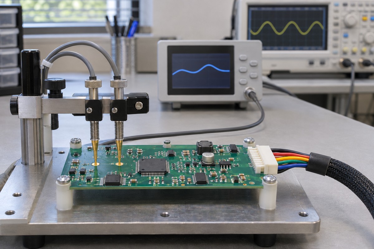
EBest Circuit’s PCB Manufacturing and Assembly Capabilities for Engine Monitors
EBest Circuit provides PCB fabrication, component sourcing and SMT/THT assembly for engine-monitor acquisition, interface and display boards.
| FR-4 fabrication item | Standard capability | Special-process capability |
|---|---|---|
| Layer count | 1–10 layers | 10–32 layers |
| Minimum finished hole diameter | 0.20 mm | 0.15 mm |
| Maximum through-hole aspect ratio | 8:1 | 10:1 |
| Minimum line width/spacing, 1 oz copper | 4/4 mil | 3/3 mil |
| Four-layer minimum board thickness | 0.6 ± 0.1 mm | 0.4 < thickness < 0.6 mm; ±0.1 mm |
| Six-layer minimum board thickness | 0.8 ± 0.1 mm | 0.6 < thickness < 0.8 mm; ±0.1 mm |
Layer count, thickness, hole size and copper features are reviewed together. For builds with 8 or more layers, high-Tg material and the exact construction are confirmed during engineering review.
| PCBA item | Capability |
|---|---|
| Assembly types | SMT, THT and mixed assembly |
| Minimum SMD package code | 01005 |
| Minimum BGA pitch | 0.25 mm |
| Maximum component dimensions | 50 × 150 mm; subject to project review |
| Component supply formats | Reels, cut tape, tubes, trays and loose parts |
| Assembly lead time | 1–5 days after material readiness, process/test preparation and schedule confirmation |
Assembly time excludes component procurement, bare-board fabrication and shipping. DFM review, sourcing and prototype PCB assembly support development builds, with inspection and functional testing arranged to the agreed specification.
Engine Monitor FAQs
Can an engine monitor work without a built-in screen?
Yes. An acquisition module or gateway can send data to a separate compatible display or recording device. The display and module must support the same data format and required functions.
Does a diesel engine monitor always need extra EGT probes?
No. Some installations provide usable exhaust-temperature data through the engine electronics, while others require additional probes. The available sensors and supported data determine what can be displayed.
Can one engine monitor serve two engines?
Some systems support multiple engines. Each input and received message must remain associated with the correct engine, and channel capacity must cover the intended installation.
Does a monitor continue recording when the engine is off?
That depends on its power connection and firmware. Some units stop with switched power, while others retain power for controlled shutdown or additional recording. Standby current matters when a unit remains connected to the battery.
Does conformal coating make an engine monitor waterproof?
No. Coating can protect suitable board surfaces against certain environmental exposure, but enclosure seals, connectors and cable entries determine much of the finished product’s ingress protection.
Is a custom engine monitor PCB the same as a complete instrument?
No. A bare PCB provides the interconnections, and a PCBA adds mounted components. A complete instrument also needs the appropriate firmware, sensors, enclosure, calibration and product-level validation.
An engine monitor depends on consistent interaction between its measurement inputs, power circuitry and assembled hardware. EBest Circuit brings PCB fabrication, component sourcing, mixed-technology assembly and inspection into one manufacturing workflow, helping development teams reduce handoffs between board production and assembly. To discuss prototype or repeat-production requirements, visit Contact Us and complete the form at the bottom of the page, or email sales@bestpcbs.com.