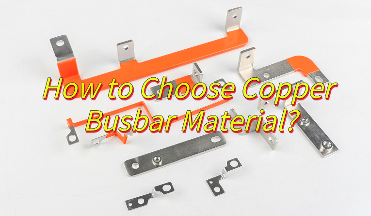
Standard copper busbar sizes can shorten sourcing time, but width and thickness alone do not make a part safe or ready to build. If material, current conditions, hole pattern, finish, and tolerances are unclear, the result may be overheating, poor terminal alignment, enclosure interference, or a quotation based on the wrong part.
This matters when the busbar connects to a PCB, terminals, or an assembled power module. A small dimension change can affect mounting holes, clearances, tool access, and the assembly sequence. If you send us the released busbar drawing and PCB files, the EBest Circuit (Best Technology) team can review the manufacturing interfaces together, point out missing quotation details, and help you define a practical PCB/PCBA, inspection, and testing scope. Your engineers keep control of the electrical design and final approval; our role is to make the handoff easier and reduce avoidable surprises before production.
Standard Copper Busbar Sizes in mm and Inches
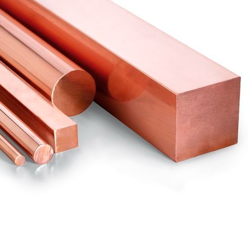
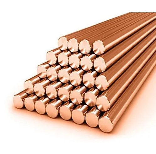
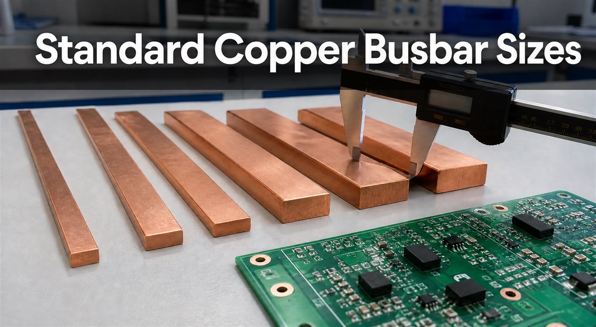
There is no single worldwide list of standard copper busbar sizes. In practice, “standard” usually means a size regularly stocked by a mill, distributor, or fabricator. Availability varies by region, copper grade, temper, length, quantity, and supplier.
Metric tables commonly show width × thickness, such as 40 × 5 mm. North American tables may show thickness × width, such as 1/4 × 2 in. Always label both dimensions and units on the drawing; an unlabeled pair can be reversed during quotation or manufacturing.
Common reference thicknesses include:
- Metric: 3, 5, 6, 8, and 10 mm.
- Imperial: 1/16, 1/8, 3/16, 1/4, 3/8, and 1/2 in.
- Larger or unusual combinations may require plate cutting or a custom material order.
ASTM B187/B187M covers requirements for copper bar, bus bar, rod, and shapes and lists several copper UNS designations for electrical applications. It is a material specification, not a universal stock catalogue. The purchase order and released drawing still need the copper grade, dimensions, tolerances, finish, and any certificate requirements.
Buyer check: Confirm the exact stock form with the proposed supplier before freezing the design. A size shown online may not be available in the required grade, length, or quantity.
Standard Copper Busbar Sizes Chart
This chart is a dimensional reference, not an ampacity table. The combinations are common examples, but they are not a promise of supplier availability.
| Nominal width × thickness | Cross-sectional area | Approximate inch equivalent | Confirm before release |
|---|---|---|---|
| 20 × 3 mm | 60 mm² | 0.787 × 0.118 in. | Grade, length, cutting tolerance |
| 25 × 3 mm | 75 mm² | 0.984 × 0.118 in. | Width/thickness order |
| 30 × 3 mm | 90 mm² | 1.181 × 0.118 in. | Edge condition and flatness |
| 40 × 5 mm | 200 mm² | 1.575 × 0.197 in. | Hole clearance and bends |
| 50 × 5 mm | 250 mm² | 1.969 × 0.197 in. | Finish and contact areas |
| 60 × 5 mm | 300 mm² | 2.362 × 0.197 in. | Length and assembly envelope |
| 80 × 10 mm | 800 mm² | 3.150 × 0.394 in. | Support, hardware, tooling |
| 100 × 10 mm | 1,000 mm² | 3.937 × 0.394 in. | Enclosure space and tolerances |
Cross-sectional area equals width multiplied by thickness, but equal area does not guarantee equal performance. Shape also affects surface area, stiffness, bending, connection geometry, AC effects, and heat dissipation.
Do not silently replace a metric size with the nearest inch fraction. For example, 5 mm and 3/16 in. are close but not identical. The difference can affect holes, bends, stack height, terminal alignment, and clearances. Record every approved alternative on the controlled drawing.
How to Select Busbar Size?
Start with the customer’s validated electrical and mechanical requirements, then compare those requirements with real stock availability.
Electrical inputs:
- Continuous, peak, and fault current.
- AC frequency or DC operation.
- Ambient temperature and permitted temperature rise.
- Enclosure, ventilation, bar spacing, orientation, and parallel bars.
- Joint design, plating, allowed voltage drop, and protection strategy.
Mechanical and integration inputs:
- Space around the PCB, terminals, enclosure, and other conductors.
- Holes, slots, bends, datums, and critical tolerances.
- Supports, vibration, weight, and installation sequence.
- Finish, masking, insulation, and contact areas.
If a stocked size meets the released requirements, it may reduce lead time and waste. If it does not, use a controlled custom route instead of weakening clearances, joints, or mechanical requirements to fit a catalogue bar.
How Copper Busbar Size and Current Rating Relate
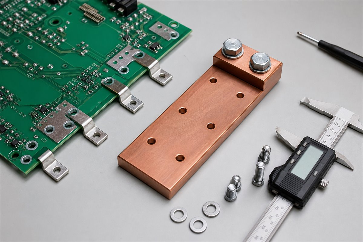
Copper busbar size and current rating are related, but there is no universal conversion from cross-sectional area to allowable current. A published value is valid only under its stated conditions.
The Copper Development Association’s rectangular-busbar data shows that temperature rise, surface emissivity, number of bars, spacing, and configuration can change ampacity. Enclosure and ventilation conditions also influence temperature rise. A bare bar in open air should not inherit the same current rating when it is enclosed, coated, stacked, or connected through poorly controlled joints.
Before accepting a current value, confirm:
- The source table, standard, calculation, or test report.
- Copper grade, dimensions, orientation, and surface condition.
- Ambient temperature and permitted temperature rise.
- AC/DC conditions, frequency, spacing, parallel bars, and enclosure.
- Joint design, terminal limits, protection, and validation method.
A size chart can narrow the options; it cannot approve the final conductor. The customer releases the rating and acceptance criteria. A useful manufacturing review then checks whether the received drawing, PCB interface, controlled dimensions, and proposed inspection or test evidence agree with that release.
Copper Bus Bar Stock or Custom Size?
Standard copper bus bar stock can reduce sourcing time when its grade, dimensions, and tolerances match the released part. A custom route is more suitable when the approved envelope, terminal geometry, bends, hole pattern, or current path cannot be met without risky substitutions.
Use stock when:
- The exact grade, condition, length, and certificates are available.
- Dimensions and tolerances meet the drawing.
- Cutting, drilling, forming, and finishing have enough process margin.
- The size does not force changes to clearances, joints, or enclosure space.
Consider custom material or fabrication when:
- Stock would create excessive machining or waste.
- A special thickness, profile, bend, or controlled edge is required.
- Hole patterns and interfaces have little tolerance with the nearest stock size.
- Validation depends on the exact released cross-section.
Project example: A buyer selects a 50 × 5 mm bar because its 250 mm² area fits an early calculation. During integration review, it blocks connector tool access and leaves too little space around an offset terminal. Changing to a narrower, thicker bar may solve the space problem but alter bending, cooling, and joint geometry. The safer next step is to compare validated options, update the mechanical stack, and release one controlled drawing before quotation.
Why integrated review matters: A busbar and PCB can each pass an isolated drawing check and still fail together. Hole patterns must align; bends and thickness must fit the enclosure; contact areas must match the assembly process; and installers need access for hardware, soldering, inspection, and rework.
How EBest Circuit supports the handoff: Our team can review the released busbar and PCB manufacturing interfaces in one quotation package, then connect that review with PCB fabrication, component-sourcing support, PCBA, inspection planning, and agreed testing coordination. We will flag unclear inputs and state the proposed scope instead of quietly making design assumptions. This gives your team a clearer decision record while electrical design, system safety, and final approval remain under your control.
Send these RFQ files:
- Released 2D drawing and a matching 3D model when the part is formed.
- Material, finish, masking, certificate, and quantity requirements.
- Critical dimensions, datums, tolerances, and inspection expectations.
- Customer-approved ratings, test inputs, and acceptance limits.
- PCB files, BOM, assembly interfaces, revision, and delivery target.
Send the controlled package, not a screenshot of a size table. Email the files and required scope to sales@bestpcbs.com; our team will review what is ready, identify what still needs confirmation, and help you define the next manufacturing step.
North American Charging Equipment PCB and Busbar Project
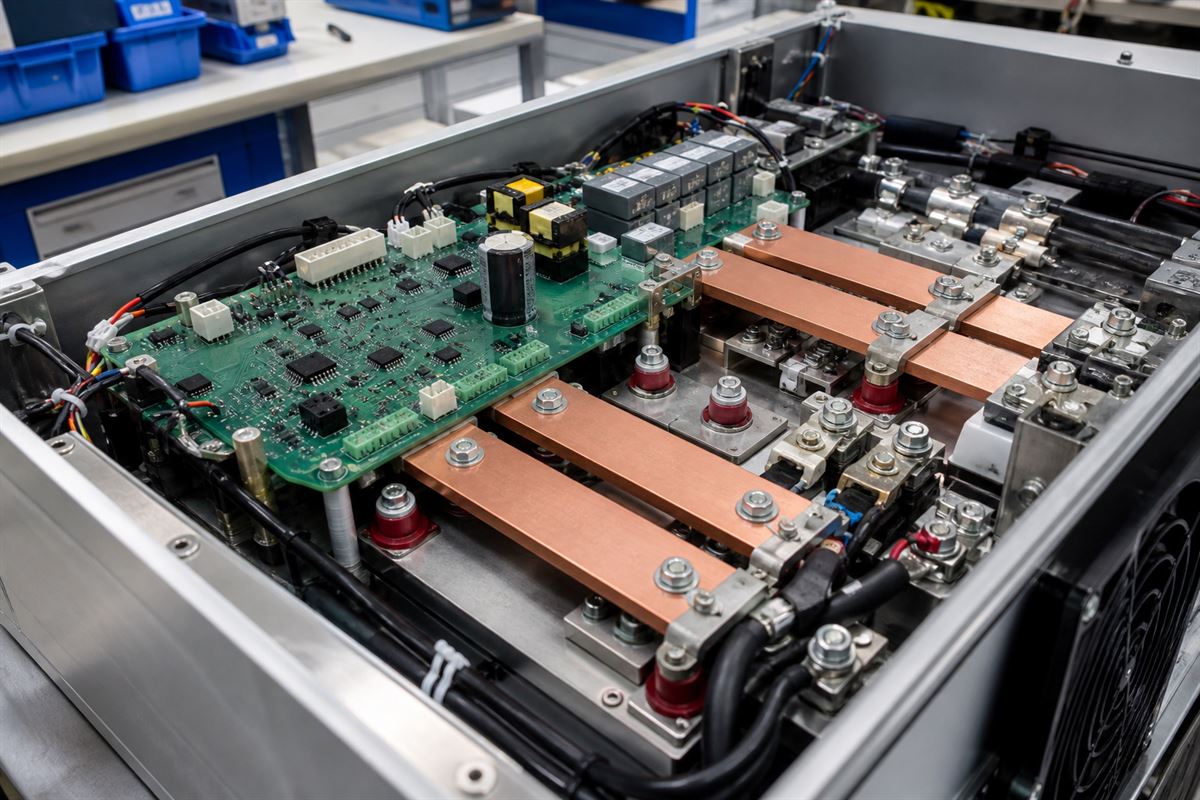
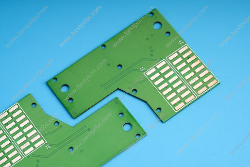
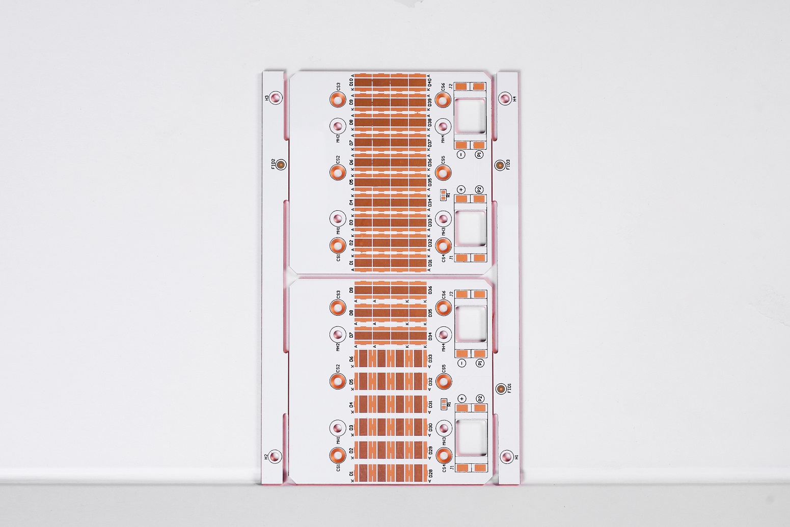
A North American customer needed 500 PCBs for charging equipment within a one-week lead time. EBest Circuit manufactured and delivered the order to these released PCB requirements:
- 2-layer FR-4 with Tg 130°C.
- 1 oz finished copper and 1.6 mm finished board thickness.
- Green solder mask and white silkscreen.
- HASL surface finish.
- Routed and delivered as individual boards rather than panels.
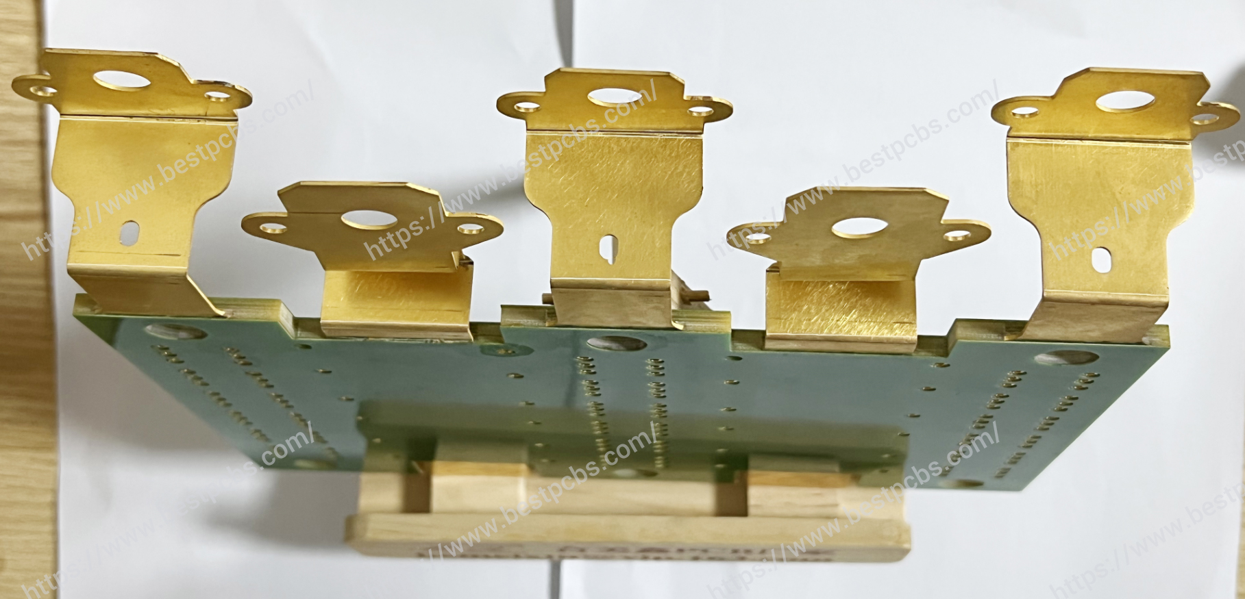
The board was used in a charging-equipment assembly with a rectangular copper busbar interface. The customer’s drawings controlled the busbar width, thickness, copper grade, finish, and current rating; the PCB’s 1 oz copper was not treated as the main current path.
To meet the one-week schedule, our team checked the PCB stack-up, drill and outline data, individual-board routing, busbar mounting holes, terminal geometry, electrical clearances, and fastener access under one revision. The 500 boards were fabricated, routed, inspected, and packed as individual pieces.
This case shows the value of sending the PCB files and controlled busbar drawing together. EBest Circuit can review the interfaces, produce the PCB, and support sourcing and PCBA when required, while the customer retains control of electrical ratings and final design approval.
FAQs About Standard Copper Busbar Sizes
Is there one universal list of standard copper busbar sizes?
No. “Standard” usually reflects recurring supplier stock. Available combinations differ by region, grade, thickness, temper, and quantity, so confirm availability before release.
Should dimensions be written as width × thickness?
Metric tables often use width × thickness, while some imperial references list thickness × width. Label the dimensions and units on the drawing to prevent reversal.
Can two bars with the same cross-sectional area carry the same current?
Not automatically. Shape, orientation, enclosure, temperature rise, spacing, joints, and surface condition can change performance. Validate the actual assembly.
Is C11000 the only copper grade used for busbars?
No. C11000 is common, but ASTM B187/B187M lists several copper UNS designations for electrical applications. Specify the required grade or approved alternatives.
What should be sent with a copper busbar RFQ?
Send the released drawing, material and finish, quantities, tolerances, inspection needs, approved ratings, assembly interfaces, revision, and delivery target.
If your busbar must align with a PCB, terminals, enclosure, or power assembly, we would be glad to look at the manufacturing package with you. Send the released files, BOM, quantities, and acceptance requirements to sales@bestpcbs.com. The EBest Circuit (Best Technology) team will point out missing quotation inputs and help define a practical PCB/PCBA, inspection, and agreed testing scope before production.
Use this guide to review Standard copper busbar sizes, then send your released PCB, busbar, BOM, quantity, and acceptance requirements to sales@bestpcbs.com.