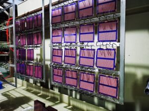
Ceramic PCB China has become a practical search topic for engineers, product developers, and sourcing teams that need circuit boards for high-heat, high-power, compact, or high-reliability electronics. The goal is usually clear: find a manufacturer that can provide stable ceramic PCB quality, suitable process advice, prototype support, and reliable communication before production begins.
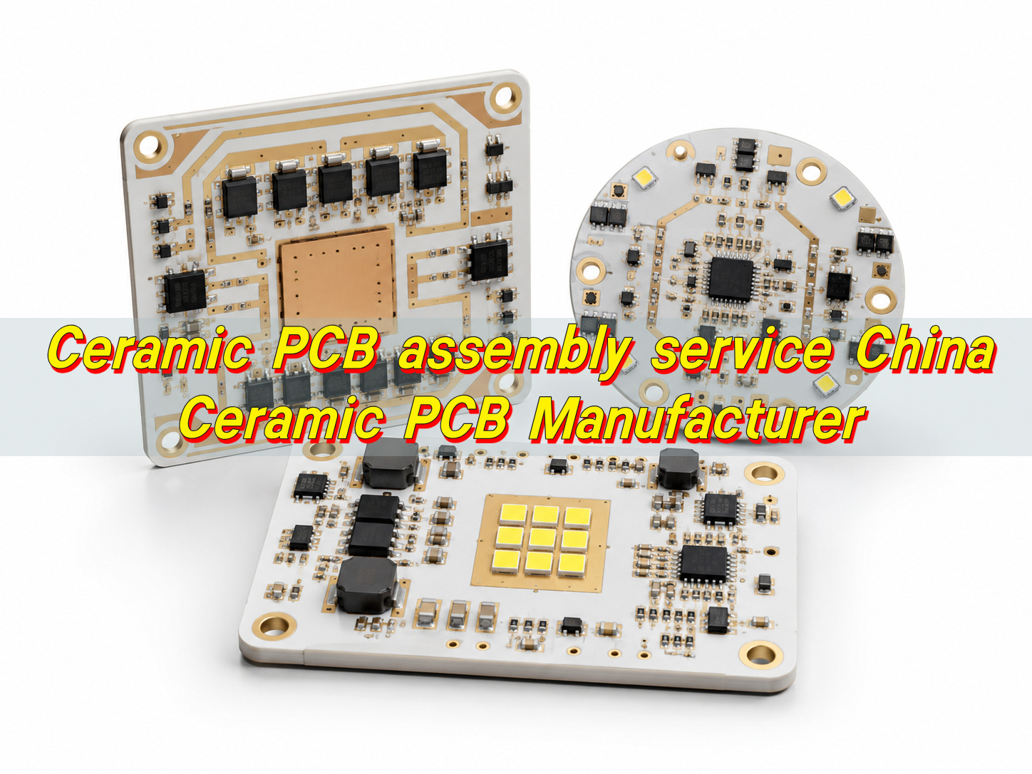
EBest Circuit supports ceramic PCB and PCBA solutions, including DPC, DBC/DCB, AMB, LTCC, HTCC, and thick-film ceramic boards. Its service scope covers design review, prototype production, ceramic circuit board manufacturing, assembly support, and quality control for applications such as medical equipment, automotive electronics, power supply, industrial control, instrumentation, radar communication, and frequency conversion braking systems.
What Is a Ceramic PCB?
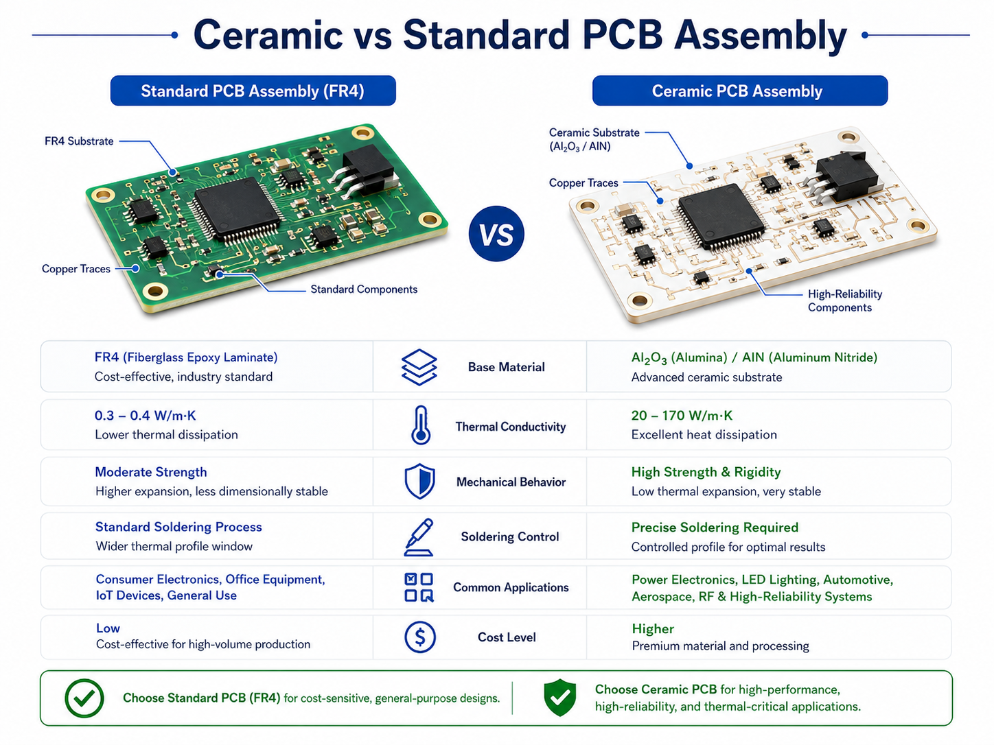
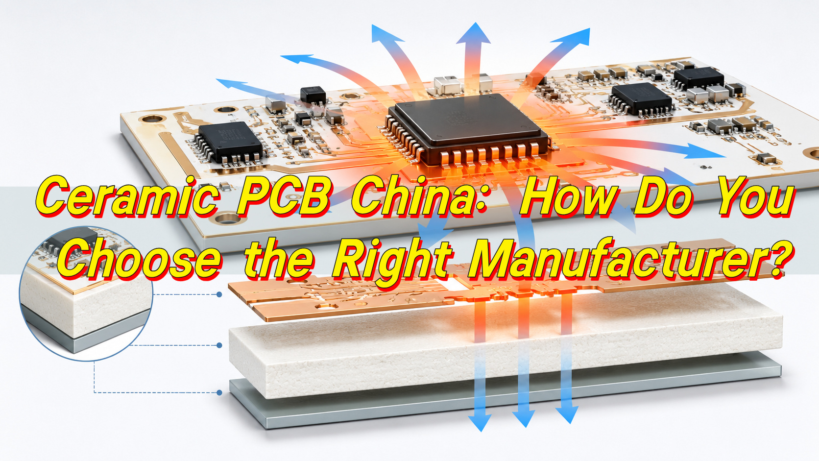
A ceramic PCB is a printed circuit board made with a ceramic base instead of a fiberglass epoxy laminate. The ceramic substrate supports the circuit pattern and helps manage heat, insulation, and mechanical stability. Common ceramic materials include alumina, aluminum nitride, and silicon nitride. Each material has different thermal, electrical, and mechanical properties.
The main reason for using a ceramic PCB is heat dissipation. In power electronics, LED modules, laser devices, RF circuits, and compact control systems, heat must move away from components quickly. A ceramic base can transfer heat more efficiently than standard FR4, which helps protect components and improve product stability.
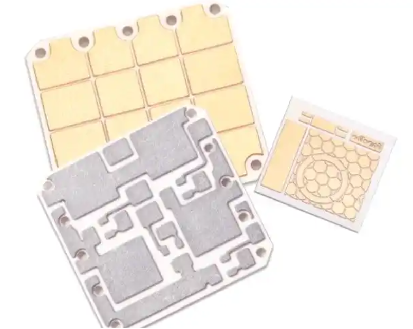
Different ceramic PCB technologies are used for different purposes. DPC ceramic PCB is often used for fine circuits and plated copper structures. DBC/DCB ceramic PCB is common in high-current power modules. AMB ceramic PCB is used where copper bonding strength and thermal cycling performance are important. Thick-film ceramic PCB is made by printing conductive paste on ceramic. LTCC and HTCC are used for multilayer ceramic circuits and compact electronic modules.
| Ceramic PCB Type | Common Feature | Typical Use |
|---|---|---|
| DPC ceramic PCB | Plated copper, fine circuit pattern | LED, sensors, medical modules, RF devices |
| DBC/DCB ceramic PCB | Direct bonded copper | IGBT, MOSFET, power modules, EV systems |
| AMB ceramic PCB | Active metal bonding, strong adhesion | Automotive power modules, new energy systems |
| Thick-film ceramic PCB | Printed conductor paste | Sensors, heaters, hybrid circuits |
| LTCC ceramic PCB | Low-temperature co-fired multilayer structure | RF modules, microwave circuits, compact devices |
| HTCC ceramic PCB | High-temperature co-fired ceramic structure | High-reliability packages and harsh environments |
A suitable ceramic PCB design should match the material, copper thickness, circuit structure, surface finish, and assembly process with the product’s real operating conditions. This is why early engineering review is important.
Why Do Customers Source Ceramic PCB from China?
Customers source ceramic PCB from China because China has a broad ceramic PCB manufacturing base, flexible prototype capability, and established supply chains for both fabrication and assembly. Many buyers also choose China ceramic PCB suppliers because they can support different ceramic technologies within one procurement channel.
Cost is one factor, but it is not the only reason. In ceramic PCB projects, process experience, production stability, inspection control, and engineering feedback often matter more than the lowest unit price. A low-cost board that does not match the design requirement can create delays during testing or assembly.
China ceramic PCB manufacturers can often support prototype, small batch, and mass production. This is useful when a customer needs to test a design before committing to volume manufacturing. A prototype can verify thermal behavior, solderability, copper adhesion, circuit accuracy, and dimensional fit.
Customers often source China ceramic PCB for several practical reasons:
- Access to DPC, DBC/DCB, AMB, LTCC, HTCC, and thick-film ceramic technologies
- Prototype support before mass production
- Flexible production quantities for development projects
- Ceramic PCB assembly service China for one-stop delivery
- Engineering review before fabrication
- Competitive production cost for complex ceramic circuits
EBest Circuit supports no MOQ limit, design challenge review, prototype confirmation, and strict quality control. This type of support is useful for customers that need samples first, especially when the board will be used in medical, automotive, industrial, or power-related products.
What Is a China Ceramic PCB Manufacturer?
A China ceramic PCB manufacturer is a company that produces ceramic circuit boards or controls the core manufacturing process directly. Its work may include substrate preparation, laser processing, metallization, copper plating, etching, printing, firing, surface treatment, inspection, and assembly coordination.
A qualified ceramic PCB manufacturer China should understand both ceramic materials and circuit requirements. Ceramic is harder and more brittle than FR4, so manufacturing rules are different. Hole size, edge clearance, conductor thickness, cutting method, surface finish, and assembly temperature all need careful review.
A manufacturer should also help customers choose the correct ceramic PCB process. For example, a high-current power module may be more suitable for DBC or AMB. A fine-line LED or sensor board may use DPC. A hybrid control circuit may use thick-film ceramic. A compact RF module may require LTCC.
EBest Circuit manufactures ceramic circuit boards and supports multiple ceramic PCB technologies, including DPC, DBC/DCB, AMB, LTCC, HTCC, and thick-film ceramic PCB. This range is helpful for customers who need to compare different ceramic base PCB solutions before finalizing a design.
What Is the Difference Between a Ceramic PCB Supplier and a Ceramic PCB Factory?
A ceramic PCB supplier and a ceramic PCB factory may both provide boards, but their roles can be different. A supplier may coordinate manufacturing, assembly, sourcing, and logistics. A factory usually focuses on direct production.
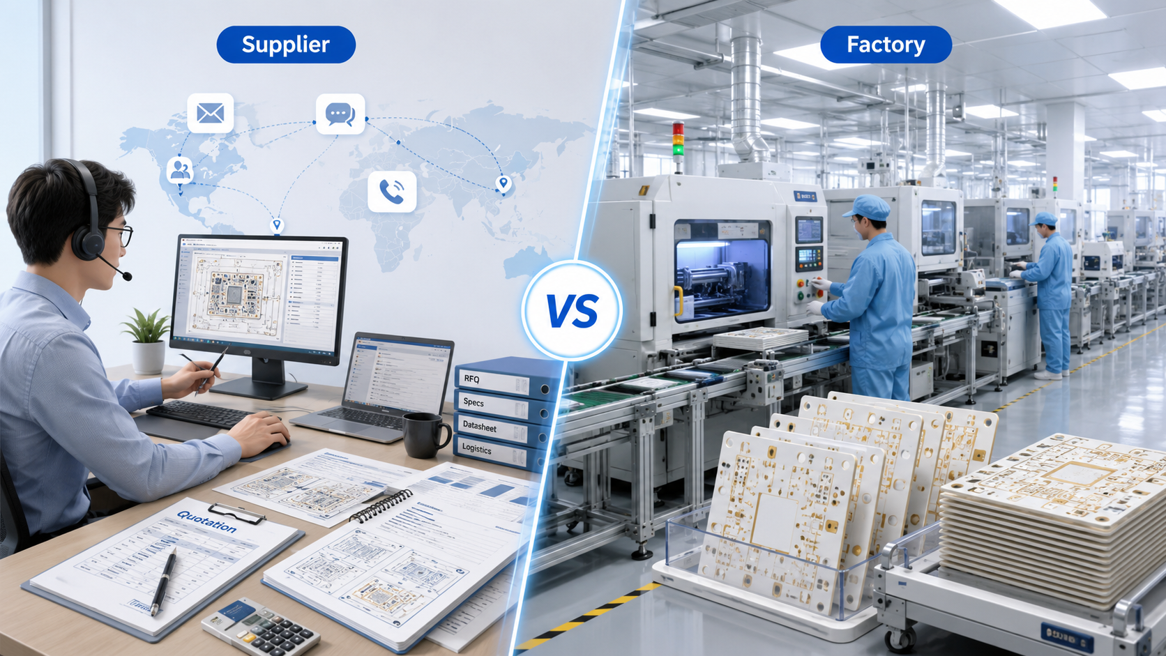
If a customer only needs bare ceramic PCBs and already has complete files, a direct China ceramic PCB factory may be suitable. If the project includes fabrication, BOM review, component sourcing, SMT assembly, testing, and export coordination, a ceramic PCB supplier China with engineering capability may be more efficient.
A supplier should not be judged only by whether it owns a factory. The important point is whether it can control quality, communicate with the production team, check technical details, and take responsibility for delivery. A factory should not be judged only by price. The key is whether it has the right process, equipment, quality system, and experience with the customer’s ceramic PCB type.
| Comparison Point | Ceramic PCB Supplier | Ceramic PCB Factory |
|---|---|---|
| Main Function | Coordinates production, service, and support | Manufactures ceramic circuit boards directly |
| Suitable For | Projects needing sourcing, assembly, and logistics support | Projects needing direct fabrication control |
| Technical Value | Depends on engineering and factory access | Depends on production process capability |
| Assembly Support | Often available through one-stop service | May be limited if focused only on bare boards |
| Buyer’s Main Check | Quality control, engineering depth, communication | Equipment, process range, tolerance, inspection |
EBest Circuit works as a ceramic PCB and PCBA solution provider, supporting both ceramic circuit board manufacturing and ceramic PCB assembly. This makes it suitable for customers who need more than bare board production, especially when prototype verification and assembly coordination are part of the project.
Can China Ceramic PCB Factories Make Prototypes?
Yes. Many China ceramic PCB factories can make prototypes, but the lead time and feasibility depend on the ceramic type, structure, tolerance, and material. A ceramic PCB prototype helps customers verify the design before mass production.
Prototype production is especially important for ceramic PCBs because these boards are often used in high-value or performance-sensitive products. A sample can help test thermal performance, solderability, dimensional accuracy, copper adhesion, surface finish, and mechanical fit.
For DPC ceramic PCB prototypes, the process may include ceramic cleaning, laser drilling, seed layer deposition, copper plating, imaging, etching, surface treatment, and final inspection. For DBC/DCB or AMB prototypes, copper bonding and ceramic preparation are more important. For LTCC and HTCC, the process may involve ceramic layers, conductor printing, stacking, lamination, and co-firing.
A prototype also gives the customer a chance to check the supplier’s communication and quality control. If the manufacturer asks clear questions, confirms key parameters, and explains process limits early, the later production stage is usually easier to manage.
EBest Circuit supports proof production before mass production. Its team confirms important values with the customer, makes samples, sends them for testing, and moves to volume production after approval. This approach helps reduce production risk and gives the customer a practical basis for decision-making.
How Is a China Ceramic PCB Prototype Made?
A China ceramic PCB prototype starts with file review. The manufacturer checks the Gerber files, drill files, fabrication drawing, material requirement, board thickness, copper thickness, surface finish, tolerance, and application notes. If assembly is required, the BOM and pick-and-place file should also be reviewed.
After the review, the manufacturer chooses the suitable process. The route may be DPC, DBC/DCB, AMB, LTCC, HTCC, or thick-film ceramic PCB. Each method has its own production flow and design limits.
A typical ceramic PCB prototype process includes:
- Technical review of design files
- Ceramic material selection
- Process selection based on application and structure
- Substrate preparation and circuit formation
- Copper plating, bonding, printing, or firing according to the process
- Surface finish and outline processing
- Electrical, dimensional, and visual inspection
- Sample delivery for customer testing
- Feedback review before mass production
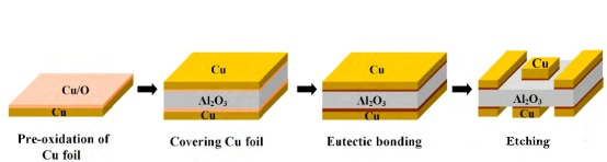
For DPC ceramic PCB, the circuit is usually made through copper deposition, plating, imaging, and etching. For thick-film ceramic PCB, conductive paste is printed and fired. For DBC/DCB ceramic PCB, copper is bonded directly to the ceramic. For AMB ceramic PCB, active metal bonding improves adhesion between copper and ceramic. For LTCC and HTCC, multilayer ceramic structures are formed through ceramic layer processing and co-firing.
EBest Circuit confirms line width, board thickness, conductor material, layer count, silkscreen, glass glaze, conductive layer material, and related values before proofing. This information helps the prototype match the design requirement more closely.
Can China Ceramic PCB Manufacturers Make Multilayer Ceramic PCBs?
Yes. China ceramic PCB manufacturers can make multilayer ceramic PCBs, but not every factory can support every structure. Multilayer ceramic PCB production requires specific equipment, material control, conductor systems, firing control, and inspection capability.
LTCC and HTCC are common methods for multilayer ceramic circuits. LTCC is used for compact modules, RF circuits, microwave devices, filters, antennas, and embedded structures. HTCC is used for high-reliability ceramic packages and circuits that need strong heat and environment resistance.
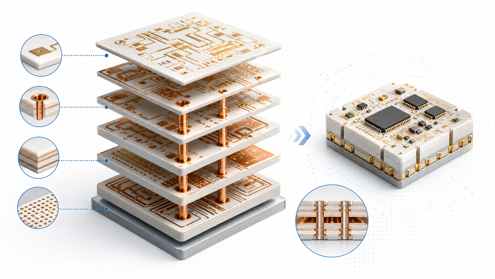
Some DPC ceramic PCB designs can also support double-sided or multilayer structures, depending on the manufacturer’s process. However, customers should confirm minimum line width, spacing, via structure, copper thickness, ceramic thickness, tolerance, and available surface finish before placing an order.
| Multilayer Ceramic Type | Main Feature | Common Application |
|---|---|---|
| LTCC ceramic PCB | Low-temperature co-fired multilayer structure | RF, microwave, compact modules |
| HTCC ceramic PCB | High-temperature co-fired ceramic structure | High-reliability packages, harsh environments |
| Multilayer DPC ceramic PCB | Plated copper structure with fine circuit capability | LED, sensor, medical, RF-related modules |
| Thick-film multilayer ceramic PCB | Printed and fired conductor layers | Hybrid circuits, sensors, control modules |
EBest Circuit offers LTCC and HTCC ceramic PCB solutions, along with DPC, DBC/DCB, AMB, and thick-film ceramic PCB. This allows customers to compare several ceramic technologies before choosing the most suitable structure.
What Applications Use Ceramic PCBs from China?
Ceramic PCBs from China are used in applications that require heat dissipation, electrical insulation, dimensional stability, and long-term reliability. The application depends on the ceramic material and production process.
In LED products, ceramic PCBs are used for high-power LEDs, UV LEDs, laser LEDs, and compact lighting modules. The ceramic base helps move heat away from the light source and supports stable light output.
In power electronics, ceramic PCBs are used in IGBT modules, MOSFET modules, rectifiers, inverters, DC-DC converters, power supplies, and EV-related systems. DBC/DCB and AMB ceramic PCBs are common in these areas because they support high current and efficient heat transfer.
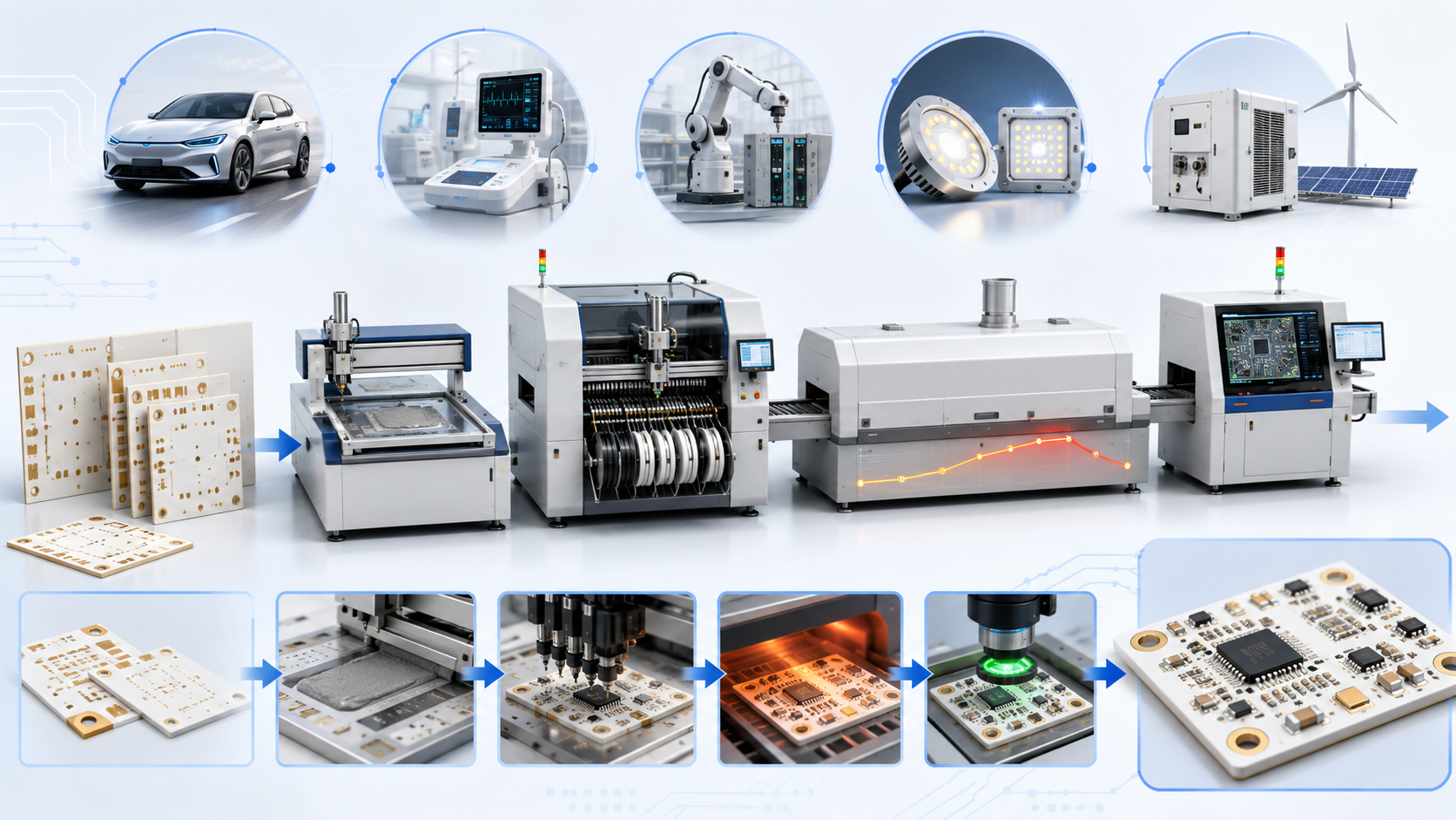
In medical electronics, ceramic PCBs are used in diagnostic equipment, monitoring systems, imaging equipment, sensors, and precision control modules. These products often require stable quality, clean assembly, and traceable production.
In automotive electronics, ceramic PCBs are used in battery management systems, charging modules, LED headlights, power control units, motor control systems, and sensors. Thermal cycling performance and long service life are important in these applications.
Other common application areas include industrial control, instrumentation, radar communication, frequency conversion braking, aerospace-related electronics, semiconductor equipment, and laser modules. EBest Circuit supports several of these industries, including medical equipment, automotive electronics, industrial control, power supply, instrumentation, radar communication, and frequency conversion braking.
What Should Customers Check Before Ordering Ceramic PCB China?
Before ordering ceramic PCB China, customers should check technical capability, material selection, process match, tolerance control, inspection methods, and assembly support. Price should be reviewed after these technical points are clear.
The first point is ceramic material. Alumina is widely used because it offers balanced performance and cost. Aluminum nitride provides higher thermal conductivity and is used in high-power and high-heat applications. Silicon nitride is often used in AMB ceramic PCB because of its mechanical strength and thermal cycling performance.
The second point is the conductor structure. DPC uses plated copper and supports fine circuits. DBC/DCB and AMB can support thicker copper for power applications. Thick-film ceramic uses printed conductor paste. LTCC and HTCC use co-fired conductor systems.
Customers should confirm the following before ordering:
- Ceramic material and thickness
- Copper thickness or conductor material
- Minimum line width and spacing
- Hole size, slot size, and outline tolerance
- Surface finish
- Working voltage and current load
- Thermal requirement
- Assembly method and soldering profile
- Testing and inspection requirements
- Prototype lead time and production capacity
- Traceability and quality documentation
A capable China ceramic PCB supplier should ask technical questions before production. This is a sign of process control, not a complication. EBest Circuit confirms key values before sample production, then supports prototype testing and mass production after approval.
What Files Should You Send to a Ceramic PCB Manufacturer China?
To receive an accurate quotation from a ceramic PCB manufacturer China, customers should send complete production files. A simple drawing or screenshot is usually not enough for ceramic PCB pricing because material, tolerance, copper thickness, and process route strongly affect cost and feasibility.
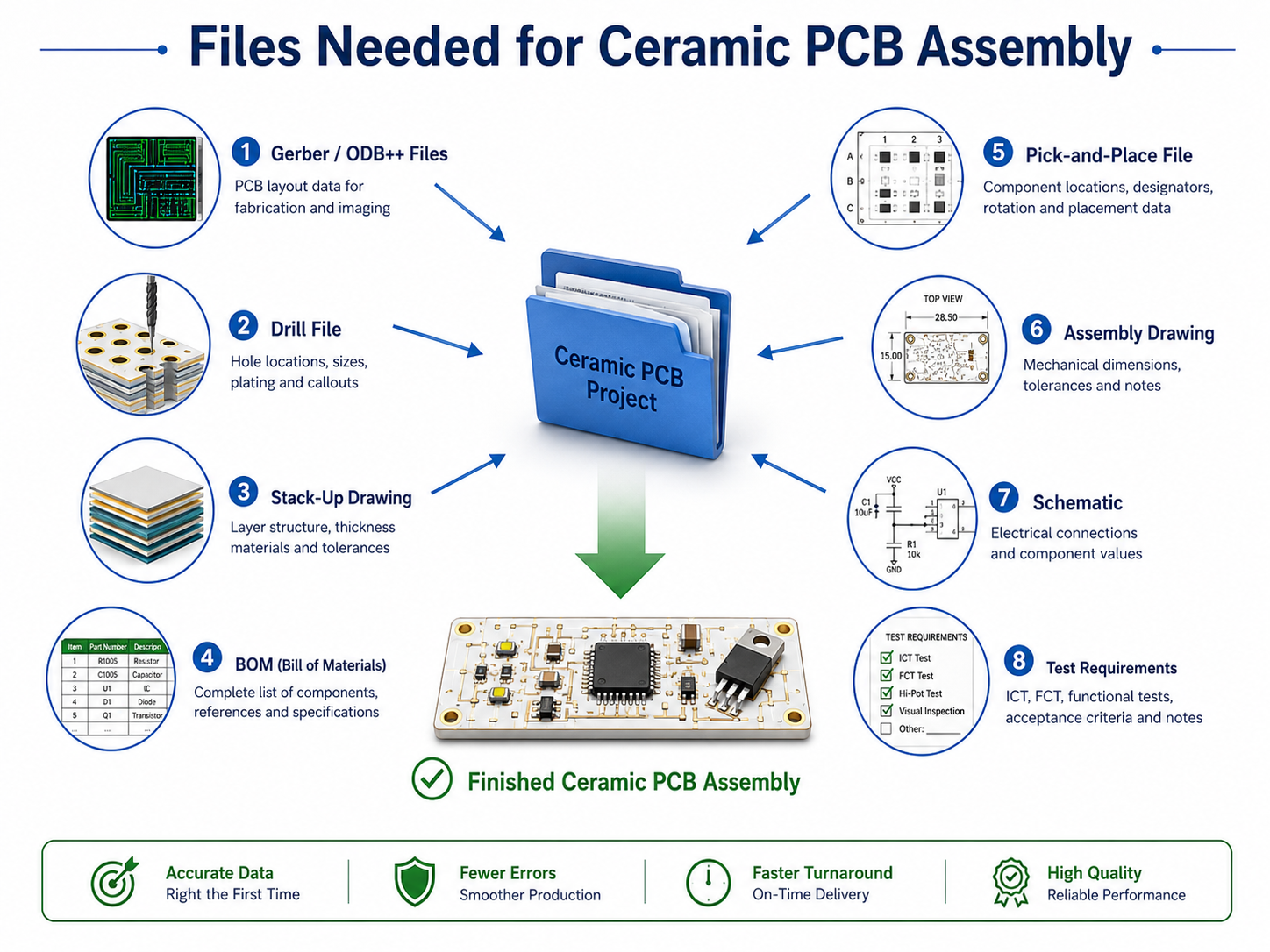
The basic file package should include Gerber files, drill files, and a fabrication drawing. The Gerber files show circuit layers, solder mask, silkscreen, paste layer, and outline. Drill files show holes, slots, and vias. The fabrication drawing should define board size, material, thickness, copper thickness, tolerance, surface finish, quantity, and special notes.
For China multilayer ceramic PCB, a stack-up drawing is also needed. It should show layer order, ceramic thickness, conductor layers, via structures, and material requirements. For ceramic PCB assembly service China, the customer should also send a BOM, pick-and-place file, and assembly drawing.
A complete quotation package usually includes:
- Gerber files
- Drill files
- Fabrication drawing
- Stack-up drawing for multilayer ceramic PCB
- BOM for assembly
- Pick-and-place file
- Assembly drawing
- Test requirement
- Packaging or labeling requirements
Complete files help the manufacturer provide more accurate pricing, better lead time estimation, and more useful DFM feedback. They also help avoid changes after production has started.
How Does Ceramic PCB Manufacturing Work in China?
Ceramic PCB manufacturing in China begins with engineering review. The manufacturer checks whether the design matches the selected ceramic material and production process. This step helps identify issues related to copper thickness, line spacing, hole design, board shape, surface finish, or assembly compatibility.
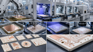
After review, the production process is selected. DPC ceramic PCB may involve ceramic cleaning, laser drilling, seed layer deposition, electroplating, imaging, etching, stripping, surface finishing, forming, and inspection. DBC/DCB ceramic PCB uses direct copper bonding to create a high-current structure. AMB ceramic PCB uses active metal bonding to improve copper-to-ceramic adhesion.
Thick-film ceramic PCB uses screen printing and high-temperature firing. Conductive paste, resistor paste, glass glaze, or protective layers may be printed depending on the design. LTCC and HTCC use ceramic layers that are processed, printed, stacked, laminated, and co-fired to create multilayer structures.
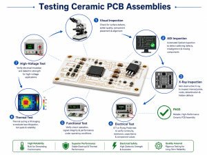
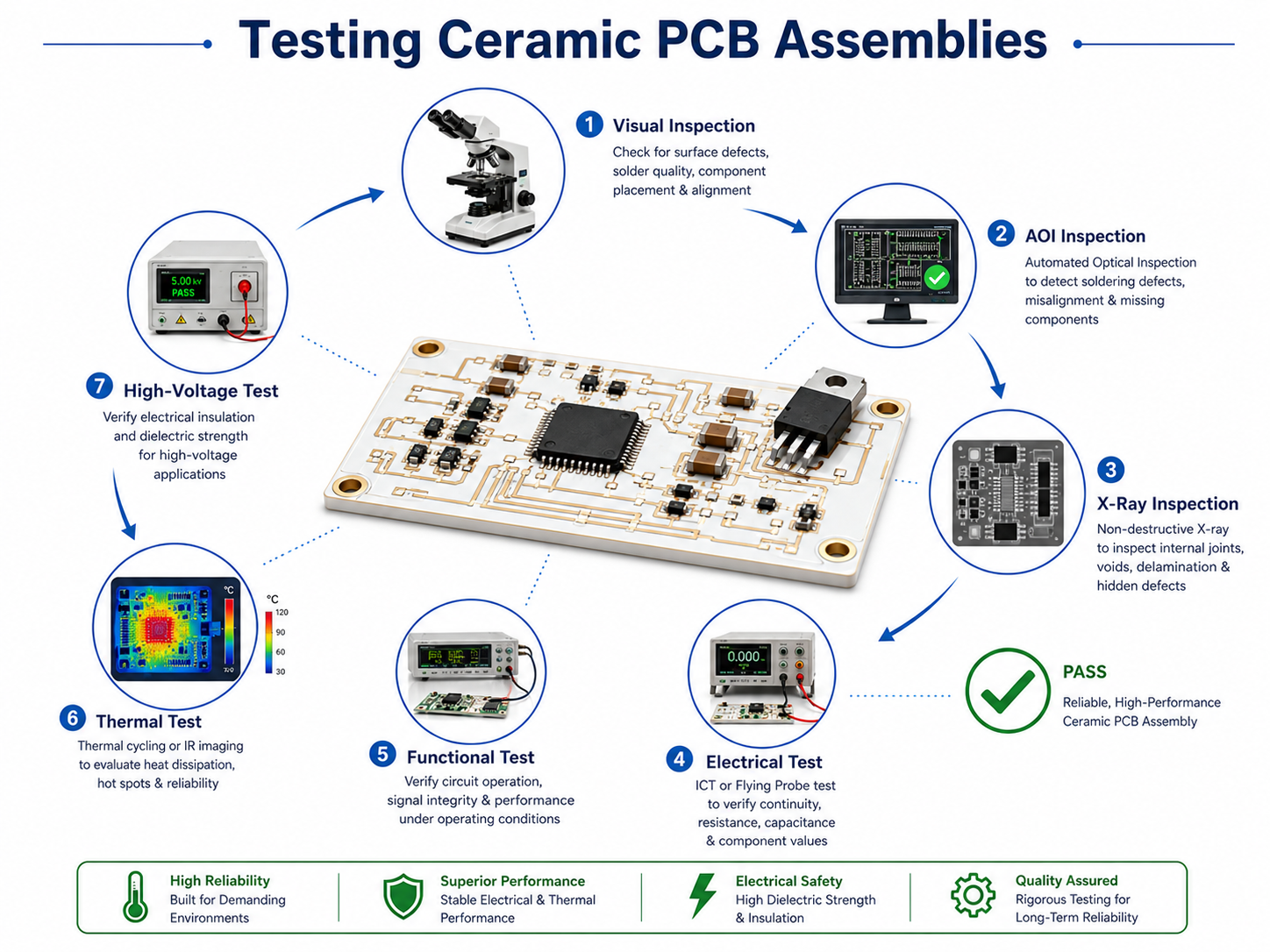
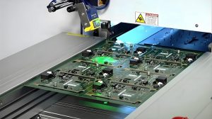
Inspection is required throughout production. Common checks include substrate quality, copper adhesion, conductor width and spacing, hole position, board outline, surface finish, electrical continuity, and appearance. For assembly projects, inspection may also include solder paste inspection, AOI, X-ray, first article inspection, ICT, or functional testing.
EBest Circuit combines ceramic PCB manufacturing with prototype confirmation and assembly support. Its production control process is designed to support rapid production, quality stability, short lead time, and fast delivery for ceramic circuit board projects.
What Is Included in Ceramic PCB Assembly Service China?
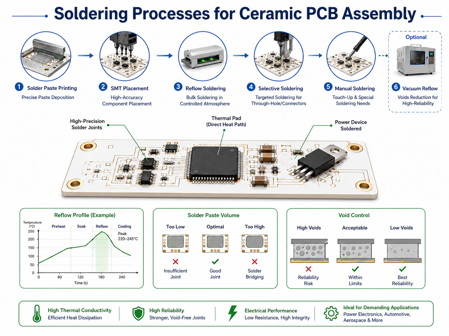
Ceramic PCB assembly service China usually includes ceramic PCB fabrication, component sourcing support, solder paste printing, SMT placement, reflow soldering, inspection, testing, cleaning, packaging, and shipment. Some projects may also require manual soldering, wire bonding, die attach, conformal coating, heat sink mounting, or functional testing.
Assembly on ceramic PCB needs controlled process settings. Ceramic substrates conduct heat differently from FR4 and can be more brittle during handling. The assembly team should review solder paste type, stencil design, reflow profile, component package, fixture support, and thermal mass before production.
A one-stop ceramic PCB assembly supplier can reduce communication work for the customer. When the same team reviews fabrication and assembly, it is easier to confirm pad design, surface finish, solderability, component placement, test points, and packaging requirements.
For ceramic PCB assembly, customers should check whether the supplier can support BOM review, component verification, SMT assembly, AOI inspection, X-ray inspection for hidden solder joints, electrical testing, functional testing, final inspection, and traceability documentation. These points are especially important for medical, automotive, industrial, power, and communication products.
EBest Circuit provides ceramic circuit board assembly and related solutions, covering ceramic PCB design, manufacturing, prototype verification, and production support. Its ceramic PCB capability includes thick-film, AMB, DPC, DBC/DCB, LTCC, and HTCC technologies.
In summary, choosing the right ceramic PCB China partner means checking material knowledge, process capability, prototype support, assembly experience, inspection control, and engineering communication. A suitable manufacturer should help confirm the correct ceramic PCB technology, review important design values, produce testable samples, and support stable production after approval.
For ceramic PCB manufacturing, China ceramic PCB prototype, China multilayer ceramic PCB, or ceramic PCB assembly service China, contact EBest Circuit at sales@bestpcbs.com.