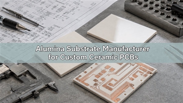
Use ceramic laser scribing when the substrate should stay in a panel through later operations and can be separated along an approved break line. Use through-cutting when the final profile needs shapes or edge control that a fracture line cannot reliably provide. A scribe line can be placed accurately and still yield an unacceptable finished edge.
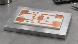
Consider a fired alumina panel carrying rectangular sensor substrates. Straight edges can potentially be scribed and separated. If a revision adds a corner notch close to a conductor, decide whether that feature still belongs on the break line or now needs a different profile operation. Compare the finished edges, not just the marks left by the laser.
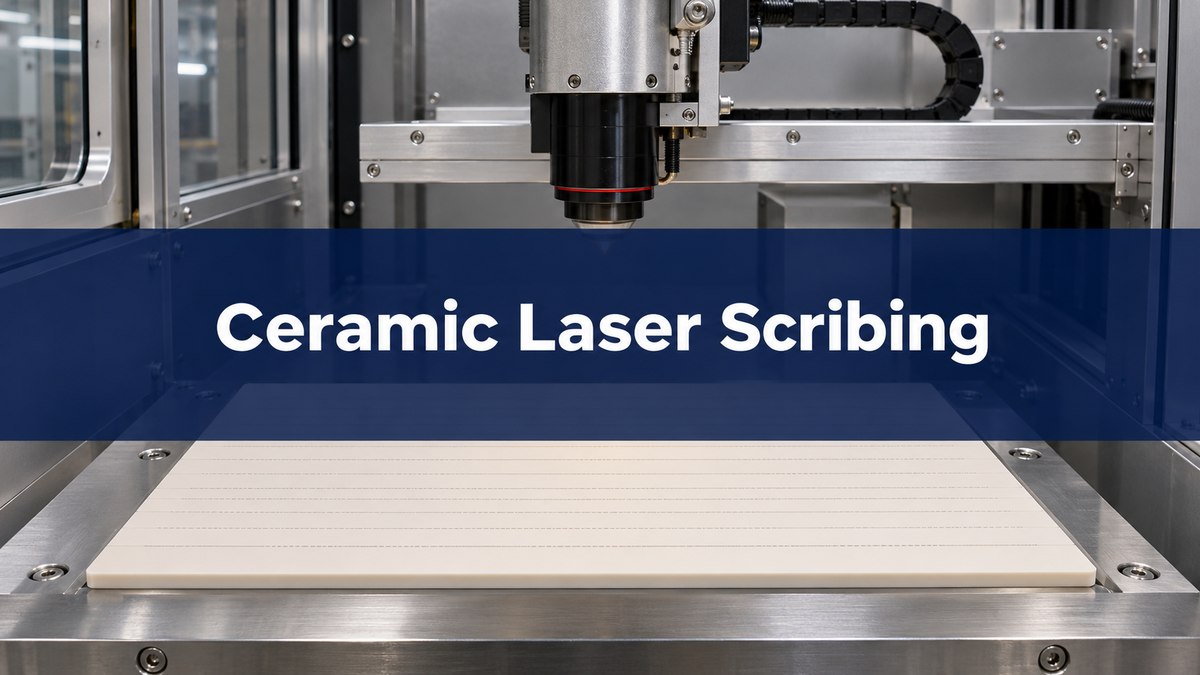
Laser Scribing: Leave Enough Ceramic to Hold the Panel
A ceramic scribe creates a controlled weak line without cutting all the way through. Some laser processes make a row of closely spaced blind holes. The remaining ceramic holds the array together until controlled separation. Pulse spacing and depth influence the path the crack takes between holes and through the remaining material.
The process has to satisfy two different conditions: the panel must survive handling before separation, then break along the intended path without damaging the product. A deeper line can reduce remaining material, but that does not by itself prove a better process; too weak a panel can fracture prematurely. Include the handling stages in the trial.
Alumina Substrate Thickness: Calculate the Remaining Section
For example, in an assumed 0.635 mm fired substrate, a 0.230 mm one-sided scribe leaves about 0.405 mm of ceramic directly below the stated deepest point. The assumed scribe depth is about 36.2% of thickness. Neither value is a recommended depth or acceptance limit.
For a one-sided feature, residual depth at that measurement location is substrate thickness minus scribe depth. A perforated line has intact bridges between its holes; a local cross-section is not the same as a uniform remaining web across the entire line. For qualification, record the depth definition and how it was measured. Use the actual thickness and process variation, not just nominal dimensions.
| Parameter on the trial drawing | Record | Why it matters |
|---|---|---|
| Fired substrate thickness | Nominal and limits, ceramic grade. | Defines the material available to hold the array. |
| Scribe depth and pitch | Definition, tolerance, and measured sample locations. | Distinguishes a measured line from a nominal laser setting. |
| Scribe line location | Datum and pre-separation tolerance. | Checks alignment to the panel artwork. |
| Finished outline and edge condition | After-separation size, edge limits and critical locations. | Shows whether the delivered tile actually fits and remains usable. |
Alumina Ceramic Laser Cutting: Scribe-and-Break Vs Through-Cut
Scribe-and-break favors compatible straight break lines and retained panel handling. A through-cut follows a machining path and separates the outline without intentionally breaking a ceramic web along that line. Depending on the process and drawing, through-cutting may allow corners, notches or contours that a clean break is unlikely to follow.
| Decision | Scribe and separate | Through-cut |
|---|---|---|
| Shape | Prefer approved straight intended breaks. | Consider for notches and nonstraight profiles within the supplier’s capability. |
| Panel retention | Remaining ceramic bridges support the process until separation. | Plan how individual parts are held or transferred once cut. |
| Main edge concern | Breakout, chips or crack departure from the intended line. | Kerf, taper and laser-affected edge condition. |
| What to approve | Intact panels plus finished parts produced by the intended break sequence. | Finished dimensions and condition at both faces and around corners. |
For the notched sensor tile, moving the conductor may restore enough clearance for the straight portion to remain scribed. If the notch is essential and the break route cannot produce it within limits, use an approved cutting operation. Do not assume a hybrid route is allowed without checking the transition and the handling sequence.
Laser Cut Kerf Width: Keep Tool Path and Finished Edge Separate
Kerf is the material removed by the cutting path. The programmed centerline is not necessarily the finished part boundary. For a full cut, ask about offset, measured width and taper on the selected ceramic and thickness. For a scribed edge, the visible line width does not bound the later fracture or chipping.
Dimension the finished feature relative to the mating or electrical datum. In the example, the qualification must show that the least remaining clearance between the conductor and the actual finished edge is acceptable. The pre-break laser drawing alone cannot establish it. Retain an explicit distinction between nominal path, pre-break inspection and final part dimensions.
Laser Cutting Heat Affected Zone: Check the Edge That Will Be Used
Check for laser-related surface or edge changes where they could affect subsequent metallization, bonding or product acceptance. Conditions depend on the ceramic, laser process and process order. A visible change is evidence to investigate, not an automatic measurement of heat-affected depth.
Tell the fabricator whether the ceramic is processed before or after metallization and which nearby features are sensitive. Compare the pilot to a reference sample using the agreed method. If reliability depends on unseen cracking, an ordinary top-view inspection cannot demonstrate its absence. See the separate ceramic edge-chipping guide for interpreting visible edge damage.
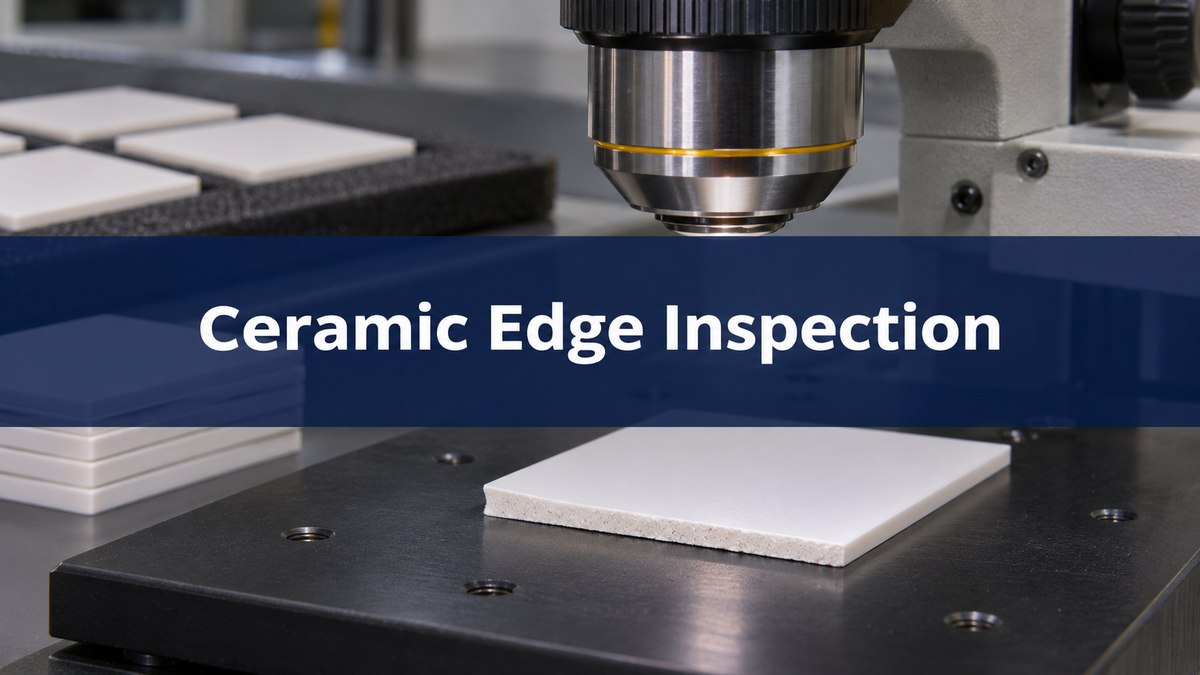
PCB Depaneling Methods: Plan How the Ceramic Is Supported
Choose the separation method for the actual ceramic and panel state, not by copying a fiberglass PCB work instruction. Establish which side is scribed, how the panel is supported, and in what order the strips and individual parts are separated. Changes in support can alter where load enters the remaining ceramic.
For the sensor panel, compare corner units and middle units separately rather than breaking off a single easy edge. Inspect any narrow bridges or geometry transitions first. If the design needs to be separated after metallization or assembly, validate the condition of those added features too.
PCB Depaneling Process: Qualify the First-Article Sequence
Accept a separation route only after checking its results before and after the break or cut. At the pilot, use the same grade, thickness and layout intended for production. Match the inspection to the actual processing order rather than an unrepresentative bare test piece alone.
- Before machining, verify artwork revision, ceramic grade, thickness, intended final outline and vulnerable features.
- Before separation, measure the locations and agreed scribe dimensions and check handling survival.
- After separation, check outline, contact or copper setback, edge chips and any crack indications against the agreed acceptance criteria.
- When a result fails, hold the affected sample and compare location, process stage and support. Change one factor at a time and verify the revised result.
Ceramic Substrate PCB: Put the Delivery Condition on the Drawing
Specify whether you need an intact scribed array, released strips or individually separated tiles. Note whether that condition applies before or after metallization and whether the next operation needs carrier support. Define which party owns separation and which drawing controls the finished edge.
When a supplier guide gives a scribe line location tolerance before separation, do not transfer it straight to final edge dimensions. The LCP guide separates pre-break line positioning from the behavior during separation. Ask for agreed edge and geometry limits for the actual build rather than citing a generic panelization limit meant for a different material.
FAQ
Can I specify only the percentage scribe depth?
No. Also define the ceramic thickness and state, how depth is measured, and what the panel and finished part must pass. The percentage alone does not describe pitch or remaining bridges.
Can I use the same scribe depth on aluminum nitride?
Do not assume so. Confirm the supplier’s qualified route for the exact grade and thickness. Changing ceramic material can change both machining and separation behavior.
Is a laser scribe line the same as a V-score on FR-4?
No. Both can guide separation, but how the weakened section is made and how it breaks can differ. Do not copy a depth, support rule or edge tolerance from FR-4 to fired ceramic.
Does better line placement prevent all edge chips?
No. Position matters, but fracture path, support, material and the break sequence also affect the final edge. Inspect separated first articles from representative positions.
Can a through-cut be used everywhere instead?
It may be suitable for the geometry, but check panel handling, cycle time, kerf and edge condition. A process that releases individual parts early may not fit the rest of the build.
What if metallization runs close to the break line?
Use the finished-edge clearance as the governing requirement. Review process order and look at the actual separation result before approving the distance or deciding to move the feature.
Can one clean sample prove a whole panel is suitable?
No. A sample is evidence for its location and conditions. Use the sampling plan to cover geometric transitions and relevant positions rather than relying on the most accessible part.
Who should supply the final separated dimensions?
Specify the owner and required report before ordering. A processor that delivers scribed panels may not control your downstream separation method or warrant those finished dimensions.
Technical References
- Accumet technical guide to laser processing and ceramic scribing.
- LCP alumina and AlN design guide, Rev. 07, laser scribing section.
- Kyocera high-precision laser processing overview.
For a Best Technology review, send the ceramic grade, panel and final-part drawings, thickness, metallization sequence and edge acceptance requirements to sales@bestpcbs.com. Call out which edges must remain intact through downstream operations.