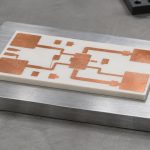
Ceramic fracture toughness measures how strongly a ceramic resists the extension of an existing crack. If an edge chip appears on a copper-clad substrate, a high flexural-strength number alone is not a reason to release it. First establish whether the chip ends at the surface or contains a crack, where the crack lies relative to the tensile stress, and what the drawing allows.
Use the material’s toughness data to screen material choices. Use the actual metallized construction and assembly conditions to decide whether the design is qualified.
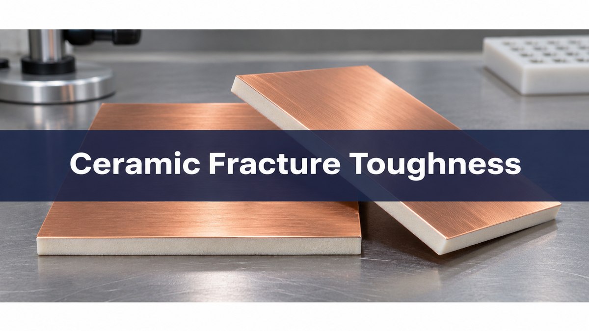
Fracture Toughness Ceramics: What the Number Measures
Fracture toughness tells you how much crack-tip loading is needed to extend a crack under defined conditions. Think of two nominally identical tiles: one has a shallow processing mark, and one has a sharp crack emerging from a corner. They can see the same nominal load, but the sharp crack concentrates stress at its tip. That local driving force, not just the applied force, determines whether the crack can propagate.
Consider a power module with a chip found near the copper edge after depaneling. Map the visible defect, note the stage where it was found and preserve affected and unaffected tiles. Treat a visible chip as a location for investigation, not as a measured crack depth. A rough notch, missing material and a sharp crack emerging from the same spot do not have identical mechanics.
Fracture Toughness Units: How to Read MPa·√m
Ceramic fracture toughness is commonly reported in MPa·√m, not in MPa. The square root of length is part of the unit because crack size contributes to the crack-tip driving force. A tensile stress of 150 MPa and a toughness of 3 MPa·√m cannot be compared directly.
If the equation uses megapascals for stress, convert the crack dimension to metres first. For example, 50 µm is 0.000050 m. Reports may also use MPa·√mm; multiply the numeric value in those units by √0.001 to convert it to MPa·√m. Also confirm whether a reported crack dimension is depth, through-crack length or a surface dimension. Converting the unit does not fix a mismatch in geometry.
Fracture Toughness KIC: What Makes a Crack Open?
KI describes the loading at a crack tip in opening mode. KIc is the critical material value for that mode under the conditions of a valid test. In a simplified linear-elastic screen, fast fracture becomes possible when the applied KI reaches the effective resistance. A result below the short-term threshold does not rule out slow crack growth or damage accumulated through repeated loading.
For a tile bonded to copper, the relevant mechanical load is not necessarily the nominal clamping force divided by area. Local bending, residual stress from joining, and differences in thermal expansion can change the tension near a copper termination. Confirm where the tensile stress acts and which direction would open the crack before treating any calculation as evidence.
Fracture Toughness Vs Strength: Which Test Answers Your Question?
Use flexural strength to compare failure stress under a specified bending method. Use fracture toughness to compare resistance to crack growth under defined crack geometry and loading. A material may perform well in both tests, but neither result can be calculated from the other without additional information about the flaw and stress field.
| Evidence | What it measures | When it helps |
|---|---|---|
| Flexural strength (MPa) | Nominal bending stress at failure in a specified specimen. | Compare strength data for matching specimens and test configurations. |
| Mode-I fracture toughness (MPa·√m) | Critical resistance of a sharp crack under defined opening-mode conditions. | Screen candidate grades when flaw size and local tensile stress are relevant. |
| Assembly qualification | Behavior of the actual copper, ceramic and mounting stack under specified loads or cycles. | Verify that a real module meets its electrical and mechanical acceptance criteria. |
For bending-test comparisons, see the ceramic substrate flexural strength guide. An impact test reports a different quantity again: the absorbed energy from one specimen and impact geometry does not directly provide KIc.
Fracture Toughness Calculation Example: How Crack Size Changes the Verdict
In a simplified example, increasing a straight edge crack from 50 µm to 100 µm raises its calculated mode-I loading from about 2.11 to 2.98 MPa·√m, with the same nominal tensile stress. These are hypothetical values, not a test result or a drawing limit.
Using KI = Yσ√(πa), let σ = 150 MPa and a = 0.000050 m. Let Y ≈ 1.12 for an ideal small, straight edge crack in a wide, uniformly loaded body. The result is 1.12 × 150 × √(π × 0.000050) ≈ 2.11 MPa·√m. Doubling a increases KI by √2 under the same assumptions.
That sensitivity is useful: an uncertain crack dimension can change whether one candidate looks close to a measured toughness value. It is not a way to turn the visible width of an edge chip into a release criterion. A real copper termination, curved surface crack or finite multilayer geometry requires a suitable model or representative test, not this fixed shape factor.
Fracture Toughness Testing Methods: How to Compare Reports
ASTM C1421 covers several ambient-temperature methods for advanced ceramics. Each uses a beam with a sharp crack, but they introduce or grow that crack differently. The standard distinguishes a precracked beam, a surface crack in flexure, and a chevron-notched beam. The results need not agree when the material’s measured resistance depends on crack size.
Ask for the edition and test variant, material grade, orientation, specimen dimensions, temperature and the statistical basis of the value. If a datasheet lists indentation fracture (IF), keep it labeled IF; do not treat it as an ASTM C1421 beam result. A controlled crack created by an indent in one beam test is not the same as reading radial cracks in an indentation-only estimate.
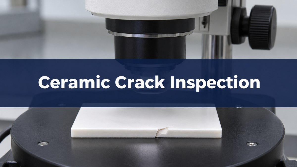
Aluminum Nitride Vs Silicon Nitride: When the Trade-off Matters
In one supplier’s comparison, its silicon nitride entry has higher reported IF toughness, while its aluminum nitride entry has higher reported thermal conductivity. Neither is automatically the better substrate: decide whether the design is constrained mainly by crack resistance, heat flow, or both.
| CeramTec entry | IF toughness (MPa·√m) | Thermal conductivity (W/m·K) |
|---|---|---|
| Aluminum nitride (AlN) | 3.0 | 170 |
| Silicon nitride (Si3N4) | 6.5 | 90 |
These are the data in the specific supplier comparison, not grade-independent ranges or guarantees. A thinner ceramic can change the thermal trade-off, but its electrical isolation, flatness and handling margin must still be verified. In the example module, compare the actual required ceramic thickness and copper geometry before ranking candidates by material properties.
Ceramic Substrate PCB: What to Verify on the Actual Stack
Qualify the finished construction when the outcome depends on metallization, edges, assembly stress or thermal cycling. Bare ceramic data cannot tell you whether the actual copper bonding process created residual stresses or whether the mounted module strains a vulnerable corner.
- Contain: Record lot, locations, process stage and orientation; hold suspected damage against the drawing and inspection plan.
- Identify: Use the approved inspection method and, where needed, retained failure surfaces or a representative section to establish whether the origin is in the ceramic, at an edge, or at the copper interface.
- Compare: Test representative coupons or modules with the actual copper pattern, ceramic thickness and mounting condition. Include a known-good control.
- Verify: Use the approved environmental and mechanical load profile, then check for crack progression and confirm the required electrical isolation and other project acceptance criteria.
Where the evidence points to a machining or handling defect, address that source as well as material selection. Where damage only appears after mounting or cycling, change one meaningful variable at a time so the result can distinguish a geometry problem from a material problem.
FAQ
Is KIC the same as hardness?
No. Hardness measures resistance to local indentation under the specified method. It may affect how a surface gets damaged, but does not establish resistance to growth of a sharp crack. Ask for separate hardness and toughness data if both matter.
Can a Charpy value be converted directly to KIC?
No. Impact energy depends on the geometry, loading and failure behavior of the specimen. A direct unit conversion does not turn it into a crack-tip material property; use a qualified fracture toughness method for that comparison.
Does the thicker substrate always crack less easily?
No. Thickness can change bending stiffness, but also changes constraints and how the copper and ceramic share load. Evaluate actual support, geometry and temperature conditions instead of ranking thickness alone.
Can an edge chip pass inspection if the electrical check passes?
Not on that evidence alone. An electrical pass establishes the result of that check at that stage. Compare the chip with the approved mechanical inspection criteria and investigate any crack indication or missing limit.
Does copper peel strength replace a ceramic toughness report?
No. Peel testing addresses the bonded structure under a defined peel condition, and the failure path should be identified. It does not characterize the opening-mode resistance of a known crack in the bulk ceramic.
Can room-temperature data establish high-temperature life?
No. The property and loading may change with temperature, and repeated cycles can introduce additional damage mechanisms. Use the ambient number for material screening and validate service behavior with representative assemblies.
Should a typical toughness value be used as a lot minimum?
No. A typical value is not a guaranteed minimum. If the project requires a contractual minimum, agree on the grade, named method, specimen orientation, sampling and acceptance criteria with the supplier.
What evidence should be saved after a cracked-substrate failure?
Keep both fracture surfaces, lot identity, orientation, photos of the intact surroundings, and the stage or load at which the crack was first observed. Preserve these items so the failure origin can be compared with the drawing and process history.
Technical References
- ASTM C1421, fracture toughness of advanced ceramics at ambient temperature.
- ASTM C1161, flexural strength of advanced ceramics.
- NIST Fractography of Ceramics and Glasses and NIST-hosted review of brittle-material fracture geometry.
- CeramTec electronic substrate property comparison.
If you are comparing ceramic PCB constructions, send Best Technology the drawing revision, ceramic grade and thickness, copper layout, and the loading or damage location at sales@bestpcbs.com. Include the inspection and qualification requirements that the assembly must meet.
You may also like





Tags: ceramic fracture toughness, ceramic substrate, fracture mechanics, silicon nitride