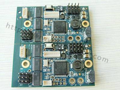
Our bga pcb assembly aerospace service combines package-specific design review, controlled SMT assembly, hidden-joint inspection, and the testing and records agreed for your application. At EBest Circuit, we support PCB fabrication, component sourcing, and assembly in one project scope. Our documented BGA capability reaches 0.25 mm pitch, subject to review of the actual package, board construction, and inspection requirements. For aerospace hardware, placing the component is only one part of acceptance: the soldering process, material handling, traceability, and customer qualification requirements must also be defined before production begins.

Key Takeaways
- Aerospace BGA assembly needs a defined combination of DFM, moisture handling, paste control, reflow, inspection, and traceability.
- Our general assembly capabilities include BGA pitch down to 0.25 mm and SMD components down to 01005; these values are not standalone aerospace qualification limits.
- PCB land geometry, via construction, solder-mask registration, and package warpage influence hidden-joint formation.
- X-ray and electrical testing answer different questions. Neither a top-down radiograph nor a successful power-up proves every joint is reliable.
- Head-in-pillow, bridging, voiding, and pad cratering require different prevention and investigation methods.
- AS9100D quality-system scope, contractual workmanship standards, inspection coverage, and acceptance records should be resolved before the build.
- Rework, underfill, alloy changes, and environmental qualification must follow the approved product requirements rather than a universal BGA recipe.
What Does Our Aerospace BGA Assembly Service Include?
We can coordinate bare-board fabrication, component sourcing, SMT assembly, X-ray inspection, and specified functional testing, with the manufacturing scope matched to your aerospace project’s approval requirements. This reduces handoffs between the board, sourcing, and assembly stages.
Our PCB assembly services include consignment, partial turnkey, and full turnkey builds. For a broader view of package handling and sourcing, see our BGA PCB assembly manufacturing overview. This article focuses on the additional process and evidence questions that aerospace buyers need to resolve.
| Assembly Item | Documented Capability or Equipment |
|---|---|
| BGA pitch | Down to 0.25 mm, subject to package and board review |
| Small SMD placement | Down to 01005, with stencil and inspection review |
| Placement equipment | Yamaha YSM20R listed in our assembly equipment information |
| Paste inspection | SINIC-TEK S8080 3D SPI |
| Optical inspection | SINIC-TEK A510DL 3D AOI |
| Hidden-joint inspection | UNICOMP AX8200 X-ray, with coverage defined for the project |
These references describe general assembly resources. The applicable manufacturing site, package construction, customer flow-downs, and qualification evidence still determine whether a specific aerospace build can be accepted. A minimum pitch does not establish the required reliability or inspection coverage by itself.
Which PCB Design Details Matter Beneath a BGA?
The most influential PCB details are the manufacturer’s recommended land pattern, pad definition, via construction, local flatness, and the routing and copper distribution beneath the package. A ball pitch alone is not enough to approve a footprint.
For example, a 0.8 mm-pitch BGA and a 0.4 mm-pitch BGA can need different escape-routing and stencil approaches. Ball diameter, populated ball map, solder-mask clearances, and available trace space determine the actual construction. We use the exact package drawing and approved board data in our PCB design and DFM review.

An open via in a soldering land can draw solder away from the intended joint. Where via-in-pad is specified, the fill, cap, and finished surface need to match the approved fabrication requirements. A solder-mask tent is not automatically equivalent to a filled and copper-capped via.
We also check board support and component access. Flexing a populated panel during handling or depaneling can load the laminate beneath BGA pads; solder-joint inspection alone may not reveal that damage.
How Are Moisture-Sensitive BGA Components Handled?
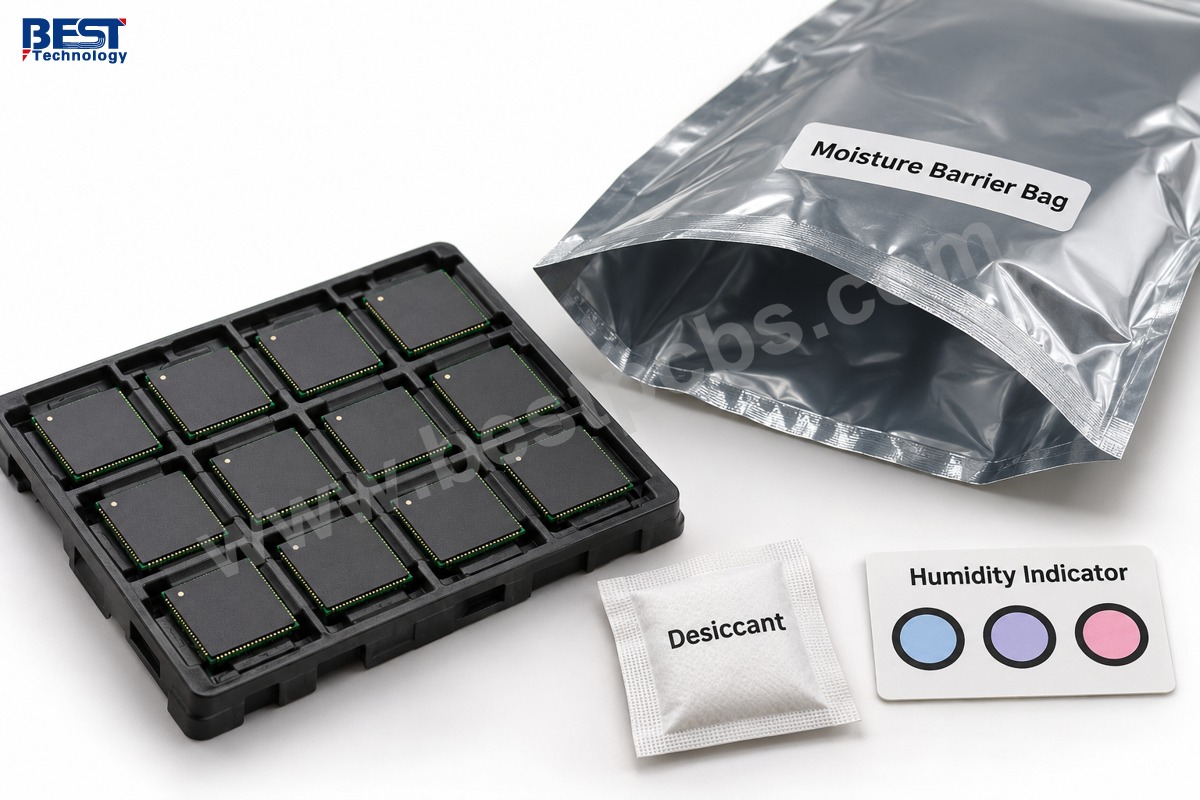
Moisture-sensitive BGAs are handled according to their package label, moisture sensitivity level, exposure history, and applicable handling requirements. Floor-life tracking and storage conditions matter before the component reaches the placement machine.
- Confirm part identity, packaging condition, lot identification, and moisture information at receipt.
- Track exposure after opening a moisture barrier bag, including material supplied by the customer.
- Use the specified controlled storage or drying procedure when needed.
- Confirm that any baking conditions are compatible with the component and its tray or carrier.
We do not treat a universal temperature and time as a safe baking recipe for every BGA. Package thickness, material, exposure condition, and supplier instructions affect the appropriate treatment. Repeated or inappropriate heating can create additional problems rather than restoring a component to an assumed original condition.
How Is the BGA Assembly Process Controlled?
The BGA assembly process is controlled by reviewing the data, measuring printed paste, verifying placement, and profiling reflow on the actual assembly before applying the agreed inspection and test plan. Each stage should provide evidence for the next one.
- Review: match the BOM, package orientation, PCB land pattern, ball alloy information, and acceptance requirements.
- Print: select paste and stencil apertures for the package and inspect deposit volume, height, area, and offset with SPI.
- Place: verify feeder or tray setup, orientation, component condition, and alignment.
- Reflow: use a measured board profile that respects paste requirements and package thermal limits.
- Verify: perform the specified X-ray inspection, electrical or functional tests, and review of build records.
Self-alignment during reflow can help a correctly designed and printed BGA settle onto its pads. It does not compensate reliably for the wrong footprint, a large placement error, an oxidized ball, or excessive package warpage.
What Reflow Controls Matter for Large BGA Packages?
Large BGAs need a measured profile that heats the hidden joints adequately without exceeding the limits of the package or nearby components. Board thickness, copper planes, package mass, and the selected alloy affect that profile.

A measured soldering profile is not the same as the oven’s displayed zone settings. Thermocouple locations should represent the thermally difficult areas of the assembly. The process review considers ramp behavior, time above liquidus, peak, and cooling in relation to the paste and component requirements.
Ball alloy and paste alloy must be considered together. A lead-free BGA placed with tin-lead paste, for example, cannot be accepted merely because the paste melted. The approved mixed-alloy process, resulting joints, and product requirements need evaluation. Neither a hotter oven nor nitrogen alone resolves every solderability problem.
What Can X-Ray Inspection Confirm Beneath a BGA?
X-ray can reveal features such as solder bridges, missing balls, solder distribution, and detectable voiding beneath a BGA. Detection of subtle opens or incomplete wetting depends on the defect geometry, viewing angle, resolution, and inspection technique.
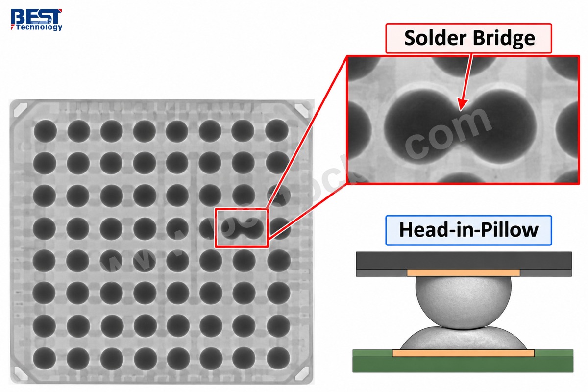
A top-down 2D image can superimpose the ball and paste deposit even when their interface is poorly bonded. Head-in-pillow therefore needs more careful assessment than checking whether every ball appears round. Additional angled imaging or specialist analysis may be needed; it should not be assumed to be included in a standard inspection arrangement.
We agree on BGA inspection coverage, acceptance criteria, and required image records before production. Optical inspection remains useful for visible components, orientation, and surrounding workmanship, but it cannot directly inspect all joints hidden under the package.
Which BGA Defects Need Different Corrective Actions?
Bridging, head-in-pillow, voiding, and pad cratering have different mechanisms, so they should not be grouped under a single “bad reflow” diagnosis. The investigation needs to connect the observed defect to materials, geometry, handling, and the thermal process.
| Issue | Mechanism to Investigate | Control or Investigation Focus |
|---|---|---|
| Solder bridge | Excess solder, poor registration, package movement | Paste deposits, stencil alignment, placement and reflow behavior |
| Head-in-pillow | Ball and paste fail to merge fully | Warpage, oxidation, flux activity and thermal profile |
| Voiding | Gas retained within the joint during soldering | Paste behavior, pad/via construction and profile |
| Pad cratering | Laminate fracture beneath or near a copper pad | Board strain, handling, depaneling and material response |
Do not apply one generic void-percentage limit to every BGA construction. Acceptance should follow the agreed package, workmanship, and product requirements. Likewise, normal continuity or a clean radiograph cannot rule out every laminate crack or latent mechanical weakness.
Which Aerospace Standards and Records Apply?
The applicable standards and records are those specified by the customer and the product’s qualification plan, including their revisions, acceptance class, addenda, and reporting requirements. BGA aerospace projects need an explicit acceptance plan rather than an assumption that “Class 3” covers everything.
J-STD-001 addresses soldering requirements, IPC-A-610 addresses assembly acceptability, and applicable space or military addenda may introduce further requirements when invoked. AS9100D addresses the supplier’s quality management system, not a blanket flight approval for every assembled board.
Our published quality information includes AS9100D and ISO 9001:2015. Supplier qualification should confirm the current certificate, legal entity, manufacturing site, and scope for the proposed order. Required records may include component lot identification, material exposure records, approved process data, inspection images, test results, and the agreed certificate of conformity.
Environmental testing is a separate question. Thermal cycling, vibration, and other qualification conditions should represent the intended hardware and mission requirements. A normal assembly functional test is not a substitute for that qualification work, and we do not imply that every such test is included in standard PCBA service.
FAQs About Aerospace BGA Assembly
Does every aerospace BGA need underfill?
No. Underfill selection depends on the package, board, stress environment, qualification evidence, and repair strategy. It changes mechanical behavior and rework access. It should be specified and validated for the product rather than added as a generic reliability upgrade.
Can a successfully powered board still have a weak BGA joint?
Yes. An incomplete or mechanically weak connection can pass an initial power-up and fail after temperature changes or strain. Test coverage, process evidence, inspection, and any required qualification should be considered together.
Is BGA rework automatically permitted?
No. Rework permission, process limits, replacement-part controls, and post-rework inspection must follow the customer’s requirements. Replacing a device adds thermal exposure and can affect the PCB pads and laminate; it needs a controlled decision, not repeated trial heating.
Does a smaller BGA pitch mean a better aerospace design?
No. Fine pitch can reduce routing area, but it can also increase fabrication, placement, inspection, and repair difficulty. Choose the package and board construction that satisfy electrical, mechanical, qualification, and manufacturing requirements together.
Can we supply our own BGA components?
Yes. We support consignment assembly. Supplied parts need approved part-number identification, usable packaging, sufficient quantity, and the traceability and moisture-handling information required by the project.
Discuss Your Aerospace BGA Build with EBest Circuit
Send your approved BOM, PCB and placement data, exact BGA part numbers, quantities, and acceptance requirements to sales@bestpcbs.com. We can review board fabrication, sourcing, assembly, and the required inspection and test scope together. Identify supplier-approval and controlled-data requirements before transferring restricted files so the project can be evaluated through the appropriate process.