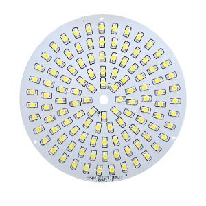
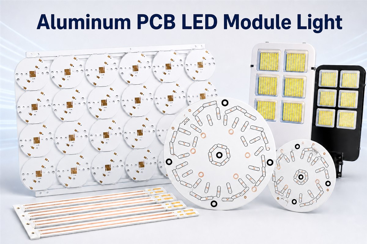
An aluminum pcb led module light can be sourced as a bare metal-core PCB, a partially assembled board, or a tested LED module ready for fixture integration. EBest Circuit supports each route through one engineering and quotation team, including MCPCB manufacturing, component sourcing, MCPCB assembly, and agreed inspection or functional testing.
Upload your Gerber files and BOM for a project-specific review. We can quote prototype and production quantities, confirm the applicable thermal material and dielectric options, and identify the files or acceptance criteria still needed before assembly.
Which EBest Circuit Service Route Fits Your LED Module Project?
The right service route depends on whether you already control the components and assembly process or want one supplier to coordinate the complete MCPCB build. Defining this scope at the start prevents a bare-board quote from being mistaken for a finished LED module quote.
| Service route | EBest Circuit scope | Best fit |
| Bare MCPCB manufacturing | Material and stack review, MCPCB fabrication, mechanical processing, surface finish, and bare-board electrical test | You manage LED sourcing, assembly, and module testing |
| MCPCB with customer-supplied components | Bare-board fabrication plus assembly using approved customer-supplied or consigned parts | You already own the component supply chain or controlled LED bins |
| Turnkey MCPCB assembly | MCPCB fabrication, BOM sourcing, SMT assembly, inspection, and agreed functional testing | You want one quotation and one production workflow for board, parts, and assembly |
| Prototype-to-production support | DFM and file review, prototype build, approval feedback, and repeat production after the build package is confirmed | You are validating a new module or replacing an obsolete lighting board |
Our Typical MCPCB Capability
At EBest Circuit, we can provide standard thermal-conductivity materials rated at 1, 2, and 3 W/m·K. High-conductivity materials rated at 3–8 W/m·K require a separate quotation. Our standard PP dielectric thickness is 100–110 µm. For 150 µm or 200 µm, please confirm with our team in advance or specify the requirement on your drawing. These values are manufacturing baselines rather than default choices for every LED design. Our typical MCPCB manufacturing capabilities are listed below for your reference.
| Capability item | Regular manufacturing baseline | Special or confirmation-required option |
| Thermal-conductivity material | 1, 2, and 3 W/m·K | 3–8 W/m·K high-conductivity grades require a separate material inquiry and quotation |
| PP dielectric thickness | 100–110 µm | 150 µm and 200 µm; confirm in advance or specify on the drawing |
| MCPCB construction | Single-sided, double-sided, and single-sided two-layer aluminum- or copper-base boards | Single-sided four-layer construction |
| Maximum processing size | 480 × 1180 mm for standard aluminum-base material | 1600 × 480 mm for single-sided aluminum-base boards |
| Minimum processing size | 50 × 50 mm | 15 × 15 mm with panelization |
| Finished-board thickness | 0.8–3.0 mm | 4.0 mm and 5.0 mm require material-order confirmation |
| Bendable aluminum construction | Not a regular construction | 0.4–1.0 mm; confirmation required |
| Inner copper | 0.5–3 oz | 4 oz and above require confirmation |
| Outer copper | 1–3 oz | Confirm 3 oz and above against the selected material and final stack |
| Line/space for 1 oz inner copper | 0.20/0.20 mm | 0.15/0.15 mm as a special capability |
| Line/space for 1 oz outer copper | 0.20/0.20 mm | 0.15/0.15 mm as a special capability |
| Minimum finished PTH | 0.45 mm | 0.30 mm requires engineering evaluation |
| Minimum finished NPTH | 1.0 mm | — |
| Maximum through-hole aspect ratio | 6:1 | — |
| Finished-hole diameter tolerance | NPTH: ±0.05 mm; PTH: ±0.075 mm | — |
| Outline dimensional tolerance | ±0.15 mm | ±0.10 mm |
| Solder-mask colors | White, black, and green | Blue, red, and yellow |
| V-CUT angle | 45° or 60° | — |
| V-CUT board-thickness range | 0.8–3.5 mm | 4.0 mm and above require confirmation |
What Is an Aluminum PCB LED Module Light?
An aluminum PCB LED module light is a populated lighting board that uses an insulated metal substrate, usually aluminum, to support the circuit and spread heat away from LED packages.
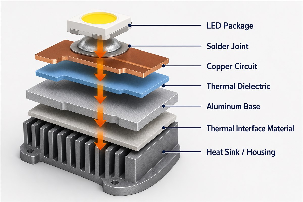
The usual stack is copper circuitry, a thin electrically insulating dielectric, and an aluminum base. LEDs and current-control components are assembled on the copper side. The aluminum base then connects to a housing or heat sink through a flat mounting surface and a suitable thermal interface material.
The phrase aluminum pcb for led light often refers only to the bare board, while a finished module also includes component selection, solder joints, connectors, optical alignment, driver compatibility, and mechanical mounting. At EBest Circuit, we can support the complete build path through custom bare MCPCB manufacturing, component sourcing, MCPCB assembly, and agreed inspection or functional testing. Customers can source the level of support they need through one engineering and quotation team instead of coordinating separate suppliers.
| Lighting application | Common board form | Main design focus |
| Downlight or spotlight | Round or compact polygon | Central heat spreading and optic alignment |
| Under-cabinet or bar light | Long linear board | Voltage drop and uniform LED spacing |
| Floodlight or outdoor fixture | Large rectangular array | Heat-sink contact, sealing, and corrosion control |
| Backlight module | Thin linear or matrix board | Brightness uniformity and low-profile assembly |
| Automotive lamp | Custom contour | Thermal cycling, vibration, and connector retention |
How Does an Aluminum PCB Move Heat Away from LEDs?
An aluminum PCB moves heat from the LED junction through the package, solder joint, copper pad, dielectric layer, aluminum base, thermal interface, and fixture housing before the heat reaches ambient air.
The aluminum base is a heat spreader, but it does not remove every thermal bottleneck. A thick or low-conductivity dielectric, a small LED thermal pad, voided solder, an uneven thermal interface, or poor housing contact can dominate the total thermal resistance. This is why selecting aluminum alone does not prove that a module will run cool.
The ams OSRAM thermal-management application note describes the full heat path from the LED through the PCB and cooling unit. It also identifies larger solder pads, thicker copper, thermally enhanced PCB material, heat spreaders, and thermal vias as design tools. For an IMS board, the dielectric should be evaluated by both thermal conductivity and thickness because heat must cross that layer before reaching the aluminum.
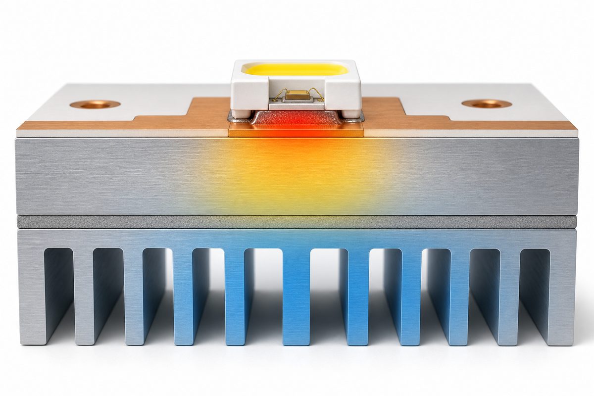
Start the thermal design with the LED manufacturer’s junction-temperature limit, junction-to-solder-point thermal resistance, electrical power, optical output, module area, ambient temperature, and expected airflow. Then calculate or simulate the complete path. A temperature measured only on the back of the aluminum base cannot by itself confirm the LED junction temperature.
Which LED Module Structures Fit Different Lighting Applications?
The best module structure is the one that matches the optical geometry, heat-flow direction, driver architecture, mounting method, and service environment of the fixture.
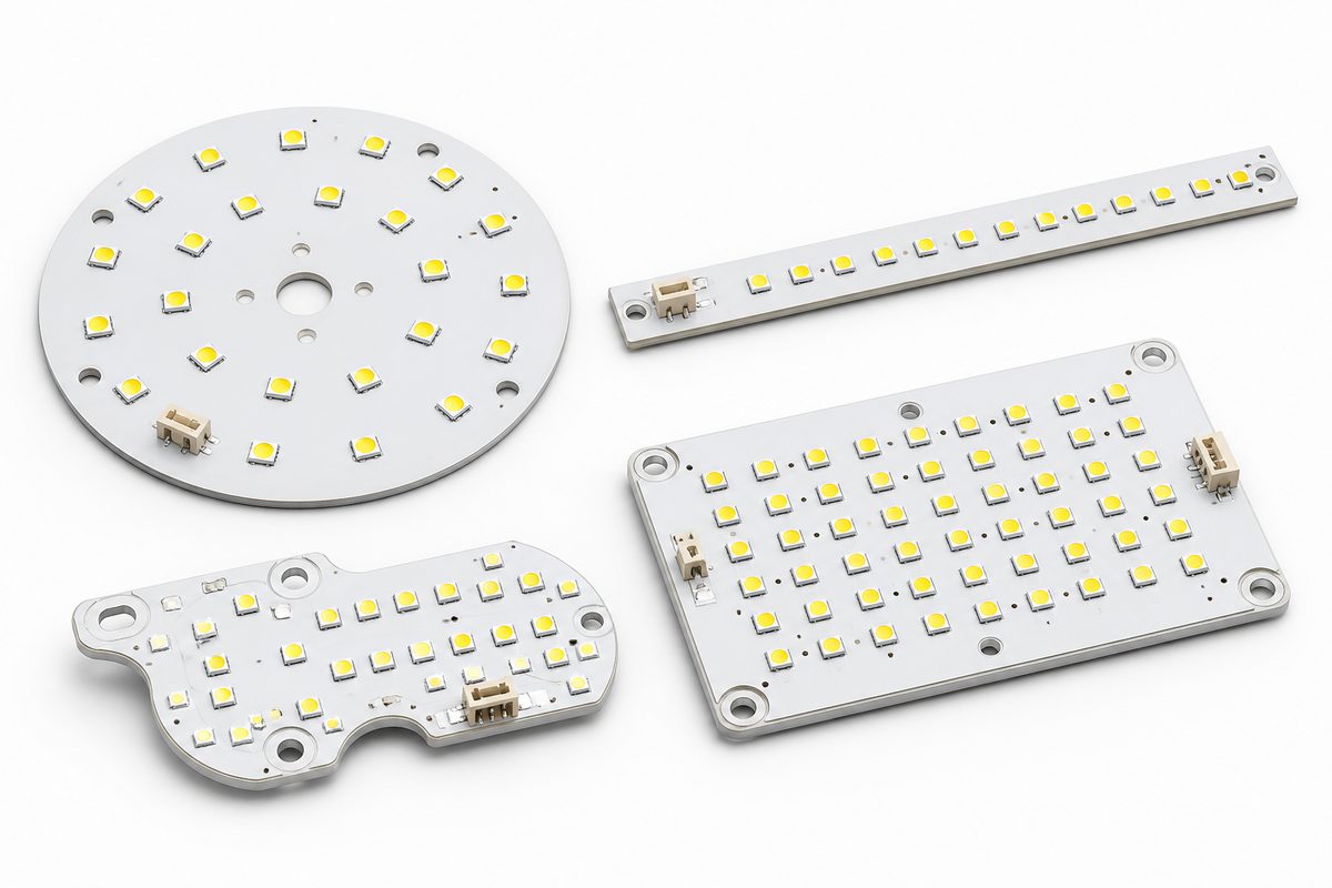
A single-sided aluminum MCPCB is the usual starting point for a compact module with components on one side and direct contact to a heat sink on the other. More complex structures may be justified when routing density, isolation, integrated driver circuits, or mechanical packaging cannot be solved on a simple board.
- Round modules: useful for downlights, spotlights, and retrofit lamps where the LED array surrounds a central optic or connector.
- Linear modules: suitable for cabinet lights, machine lights, signs, and architectural bars; review voltage drop from one end of the board to the other.
- Large arrays: used in floodlights and industrial fixtures; divide the board into current-controlled strings and check temperature uniformity across the full area.
- Custom contours: used where the PCB follows an enclosure, reflector, or vehicle lamp; confirm routing clearance near routed edges and mounting holes.
Outdoor use adds system-level requirements such as enclosure sealing, drainage, connector protection, coating compatibility, and corrosion testing. These are fixture requirements, not automatic properties of the bare aluminum PCB. Share them with our engineering team so we can include the applicable MCPCB, assembly, and test requirements in the quotation and flag any fixture-level items that need separate validation.
What Electrical Inputs Matter for a 12V Aluminum PCB LED Module Light?
A 12V label is not a complete electrical specification. To quote and build the module correctly, our engineering team needs the LED string arrangement, current-regulation method, power target, polarity, connector, dimming interface, and allowable input range.
An aluminum pcb led module light 12v may use resistor-limited strings, a constant-current driver on the board, or an external constant-current driver with a nominal 12V supply. These architectures do not behave the same under supply tolerance, LED forward-voltage variation, temperature change, or dimming.
| Required input | Design decision |
| Supply range and polarity | Defines protection, string count, and regulator headroom |
| LED part number and bin | Defines forward voltage, current, color, and thermal data |
| Target current per string | Sets brightness, power, and component ratings |
| Dimming method | Determines PWM, analog, or driver-interface requirements |
| Power and temperature limits | Sets thermal validation and derating conditions |
| Connector and wire definition | Controls current capacity, polarity, and mechanical fit |
Use the LED datasheet values rather than a generic forward-voltage assumption. For resistor-limited modules, calculate the worst-case current at the highest supply voltage and lowest expected LED forward voltage. For constant-current modules, verify driver efficiency and heat generation because the driver can create a separate hotspot from the LED array.
How Should You Select the Dielectric, Copper, and Aluminum Base?
Select the material system from the required thermal resistance, electrical isolation, copper current density, mechanical stiffness, board geometry, and manufacturing process rather than choosing the highest advertised conductivity.
| Layer or feature | Selection basis |
| Copper circuit | Current, spreading area, trace width, pad geometry, and etching limits |
| Thermal dielectric | Thermal conductivity, thickness, breakdown requirement, and adhesion |
| Aluminum base | Thickness, flatness, stiffness, weight, machining, and housing contact |
| Solder mask | Color, reflectance, cure quality, clearance, and operating environment |
| Surface finish | LED package compatibility, solderability, storage, and assembly process |
The capability snapshot near the top of this page separates our regular MCPCB manufacturing baselines from special or confirmation-required options. For stack confirmation and quotation, send us your Gerber files, stack drawing, copper requirements, finished thickness, thermal target, quantities, and any special mechanical features. Our engineering team will match the requested design to the applicable regular or special MCPCB process.
Which Layout Rules Reduce Hotspots and Brightness Variation?
A good LED module layout spreads heat and current evenly, keeps thermally sensitive parts away from local hot zones, and provides repeatable contact with the heat sink.
- Follow the LED manufacturer’s recommended land pattern, including the thermal pad and solder-mask definition.
- Use sufficient copper spreading area around each LED without creating unbalanced solderable copper that encourages component rotation or tombstoning.
- Keep high-current paths short and wide, and calculate voltage drop across long linear modules.
- Place current-limiting parts so their heat does not add directly to the hottest LED cluster.
- Balance LED spacing with optic geometry; uniform electrical current cannot correct poor optical placement.
- Keep copper and components clear of routed edges, V-cuts, mounting holes, and exposed metal according to the required isolation.
- Define flat mounting zones and screw locations that apply even pressure without bowing the board.
Our regular 1 oz outer-layer starting rule is 0.20/0.20 mm line and space, while 0.15/0.15 mm is treated as special capability. Do not use the special value to shrink power traces. Trace width still needs to satisfy current, temperature-rise, copper-thickness, manufacturing-tolerance, and connector requirements.
How Is an Aluminum LED Module PCB Manufactured and Assembled?
An aluminum LED module moves through material preparation, imaging and etching, drilling or routing, solder-mask and surface-finish processing, electrical test, SMT assembly, inspection, and functional verification.
- Material and stack confirmation: verify the thermal laminate, copper thickness, aluminum thickness, dielectric requirement, surface finish, and panel plan.
- Circuit formation: image and etch the copper while controlling power-trace width and LED pad geometry.
- Mechanical processing: drill, route, score, or form the module; isolate plated holes and exposed metal where required by the design.
- Solder mask and finish: apply the specified mask color and surface finish, then inspect registration and solderable areas.
- Bare-board test: perform continuity and isolation checks before components are added.
- SMT assembly: print solder paste, place LEDs and control components with polarity control, and run a validated reflow profile.
- Post-assembly inspection: inspect solder joints, component position, polarity, cleanliness, and the flatness of the heat-sink interface.
The metal base absorbs heat during reflow and rework, so an FR-4 profile should not be copied without verification. Record the actual board temperature near representative LEDs and heavy copper areas. Excessive rework time can damage LEDs, darken the package, disturb phosphor, or weaken the dielectric bond.
At EBest Circuit, we can review bare-board DFM, material selection, BOM availability, placement data, assembly requirements, and the agreed test plan as one manufacturing package. Our LED PCB assembly overview explains how fabrication and component assembly fit together, while our metal-core PCB capability page covers bare-board material and structural options.
How Should Thermal, Electrical, and Visual Performance Be Tested?
Test the module under the intended supply, mounting pressure, thermal interface, housing, airflow, ambient temperature, and duty cycle because an open-bench light-up test does not reproduce fixture conditions.
| Test | Measurement |
| Bare-board electrical test | Continuity, isolation, shorts, and opens |
| Powered functional test | Input current, voltage, power, polarity, and dimming response |
| Thermal validation | Defined temperature points after thermal stabilization |
| Optical check | Brightness, color, flicker, and distribution against the approved limit |
| Assembly inspection | LED orientation, solder wetting, void indicators, and component position |
| Mechanical fit | Outline, hole position, connector clearance, flatness, and housing contact |
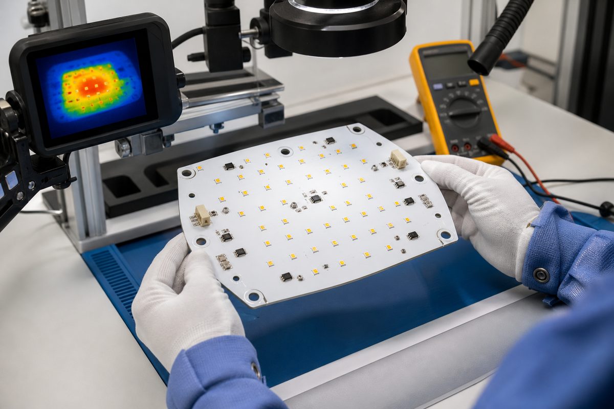
Use temperature data from the LED manufacturer’s approved measurement method when estimating junction temperature. Infrared images are useful for finding relative hotspots, but surface emissivity and reflective metal can distort readings. Thermocouples also need controlled placement and attachment. The IPC LED thermal-management resource identifies PCB area, LED thermal data, dielectric properties, thermal interface material, heat-sink area, ambient conditions, and power dissipation as connected inputs.
What Causes Early Failure in Aluminum PCB LED Modules?
Early failure usually comes from a broken thermal, electrical, mechanical, or assembly assumption rather than from the aluminum base alone.
| Failure symptom | Likely cause | Corrective check |
| Rapid light decay | High junction temperature or overcurrent | Recheck current, heat path, interface, and housing |
| Uneven brightness | String imbalance, voltage drop, LED bin mix, or hotspot | Measure each string and map temperature and output |
| Intermittent LEDs | Solder voids, cracked joints, flexing, or connector movement | Inspect joints and reproduce mechanical and thermal loading |
| Short to metal base | Isolation damage, exposed copper, or incorrect hole design | Review dielectric, edge clearance, holes, and isolation test |
| Board lifts from heat sink | Warp, uneven mounting, poor interface material, or fastener stress | Check flatness, mounting torque, contact pattern, and housing |
Failure analysis should preserve the failed module, driver, thermal pad, fasteners, and housing as one system. Record operating hours, supply conditions, ambient temperature, dimming state, mounting orientation, and whether the fault follows the board or remains with the fixture.
What Should You Check When Replacing an LED Module Light?
An aluminum PCB LED module light replacement must match more than diameter and wattage; verify the driver, LED configuration, polarity, mounting, optics, connector, thermal interface, and temperature limits.
- Measure the exact board outline, thickness, hole pattern, and LED-to-optic position.
- Record the input voltage range, current, polarity, connector pinout, and dimming method.
- Identify the LED package, count, string arrangement, color temperature, color-rendering requirement, and optical bin if available.
- Check how the original board contacts the housing, including thermal-pad thickness and fastener pressure.
- Confirm whether the printed wattage describes LED power, input power, or the complete fixture.
- Define acceptable brightness, color, temperature, and fit tolerances before approving the replacement.
Do not increase wattage simply because a replacement board fits the same opening. The driver and cooling system may not support the additional electrical and thermal load. If the original part has no drawing, send dimensioned photographs, the failed sample, driver label, connector details, and housing information before a new layout is released.
What Affects Aluminum PCB LED Module Pricing and Lead Time?
Pricing and lead time are driven by the thermal laminate, board thickness, copper weight, outline complexity, surface finish, component sourcing, assembly density, testing, tooling, panel utilization, and order quantity.
- Thermal material: high-conductivity or special-thickness laminates may require a material inquiry and longer procurement.
- Copper and geometry: heavier copper, tight spacing, isolated plated holes, countersinks, formed sections, and unusual contours add process controls.
- LED sourcing: package availability, bin requirements, approved alternatives, moisture handling, and traceability affect both price and schedule.
- Assembly and test: dedicated fixtures, controlled optical measurements, burn-in, thermal testing, and serialized records add work but may reduce field risk.
- Volume and panel use: irregular shapes and low panel utilization can raise board cost even when the individual module is small.
Send our engineering team the Gerber and drill files, schematic, BOM with approved alternatives, placement data, dimensioned mechanical drawing, LED and driver datasheets, stack and thermal requirements, test limits, quantity, and target schedule. With this package, EBest Circuit can quote the bare MCPCB, component sourcing, assembly, and requested testing together instead of pricing an aluminum PCB LED board by wattage alone.
FAQ About Aluminum PCB LED Module Lights
Does an aluminum PCB eliminate the need for a heat sink?
No. The aluminum base spreads heat, but the system still needs a path from the board into a housing, heat sink, or surrounding air. Whether a separate heat sink is required depends on LED heat, module area, dielectric thermal resistance, mounting interface, ambient temperature, airflow, and allowable junction temperature. Validate the complete mounted fixture rather than the board in free air.
Can an aluminum LED PCB be double-sided?
Yes, double-sided and more complex metal-substrate structures are possible, but they cost more and require careful electrical isolation and thermal-path planning. A simple single-sided IMS board is often preferable when LEDs can sit on one side and the opposite aluminum face can contact the heat sink. Use a more complex construction only when routing, component placement, or packaging justifies it.
Is every 12V LED module compatible with a 12V power supply?
No. Some modules accept a regulated 12V input, while others expect a constant-current driver even if the fixture is described as 12V. Check the module input range, current regulation, polarity, string arrangement, connector, and dimming method. Applying a raw 12V supply to a constant-current LED board can overdrive or damage the LEDs.
Does white solder mask improve heat dissipation?
White solder mask is often chosen for optical reflectance and appearance in lighting products. It does not replace the conductive heat path through the LED pad, copper, dielectric, aluminum base, and housing. Its reflectance, color stability, cure quality, thickness, and adhesion should be reviewed, but thermal performance still depends mainly on the complete material stack and mechanical interface.
Can through-hole connectors be used on an aluminum PCB?
They can be used when the hole structure provides reliable electrical isolation from the metal base and the fabrication process supports the required plated or non-plated geometry. Our regular minimum finished PTH starting point is 0.45 mm; a 0.30 mm finished hole requires our engineering evaluation. We review the annular ring, clearance to exposed aluminum, connector forces, soldering process, and creepage requirements before release.
What files are needed for a custom LED module quotation?
Send our engineering team the Gerber and drill files, schematic, BOM, placement data, mechanical drawing, LED and driver datasheets, target voltage and current, thermal requirements, mounting details, test limits, quantities, and schedule. We can review the package for bare MCPCB manufacturing, component sourcing, assembly, and agreed testing. For a replacement without design files, add clear photographs, measured dimensions, connector pinout, driver label, housing details, and an original sample if available.
How should a prototype LED module be approved?
For prototype approval, define the required checks for electrical input, current balance, polarity, dimming, optical output, color, thermal stabilization, mechanical fit, connector retention, and the heat-sink contact pattern under intended fixture conditions. EBest Circuit can perform agreed inspection and functional tests and report the results against supplied acceptance limits. A brief light-up inspection can find assembly errors, but it does not replace fixture-level thermal or lifetime validation.
Can a replacement LED module use a higher wattage?
Only after the driver, wiring, connector, PCB current paths, thermal interface, heat sink, enclosure, and LED junction temperature have been revalidated. Higher wattage usually means more heat even if the board outline is unchanged. A mechanically compatible module can still overload the driver or push the fixture above its thermal limit.
When is copper-core PCB preferable to aluminum?
Copper-core structures may be considered when the required heat flux, localized hotspot control, or direct-thermal-path design cannot be met with an aluminum IMS construction. Copper is heavier and generally more expensive, so the decision should be based on a thermal model, mechanical limits, and total system cost rather than material conductivity alone.
Which surface finish should an LED module use?
The finish should match LED package recommendations, solder paste and reflow conditions, pad pitch, storage duration, assembly location, and cost. Common options include HASL, OSP, immersion gold, immersion silver, and immersion tin, but no single finish is best for every module. Confirm shelf-life controls and solderability requirements with both the component and assembly processes.
How Can EBest Circuit Support Your LED Module Project?
EBest Circuit provides custom bare MCPCB manufacturing, MCPCB assembly, component sourcing, and agreed inspection or functional testing for LED module projects. We support prototype validation and scalable production through one engineering and quotation workflow, helping customers reduce supplier handoffs between the PCB, components, and assembly stages.
Send us the Gerber files, BOM, placement data, schematic, quantities, LED and driver datasheets, housing or heat-sink drawing, target operating conditions, and acceptance tests. Our engineering team will review manufacturability, material requirements, component availability, assembly inputs, and test expectations before quotation. Upload your files for review or contact us at sales@bestpcbs.com to discuss your custom aluminum PCB LED module and request a quote.