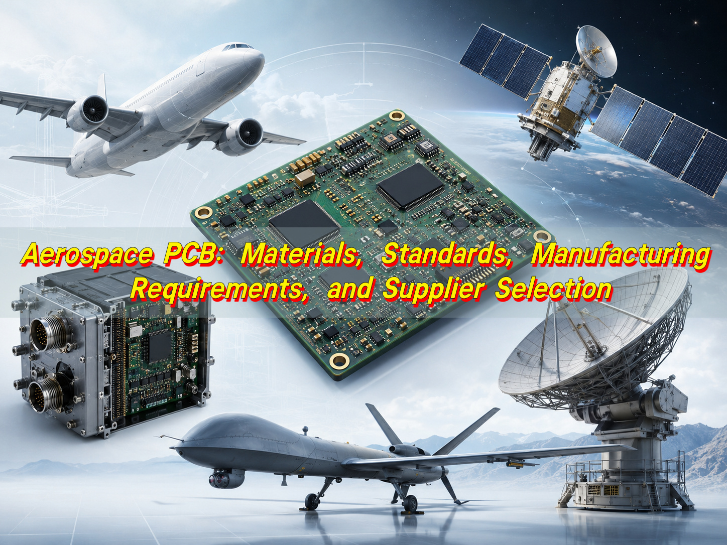
Aerospace PCB testing requirements are the inspection, verification, documentation, and traceability rules used to confirm that an aerospace printed circuit board can meet high-reliability expectations before it is accepted for use. This article explains the key standards, bare board tests, electrical testing rules, microsection and TDR requirements, aerospace PCB assembly tests, and supplier deliverables that buyers should understand before placing an order.
For many buyers, the difficult part is not knowing that aerospace PCBs should be “high reliability.” The difficult part is turning that idea into clear purchase requirements. If the RFQ only says “IPC Class 3” or “aerospace quality,” suppliers may quote differently, test differently, and deliver different levels of evidence.
Common problems usually start like this:
- The supplier says “Class 3,” but the required standard stack is not clear.
- The buyer asks for testing, but does not define 100% test or sampling.
- Microsection, impedance, and X-ray requirements are discussed too late.
- The PCBA supplier and bare board factory treat responsibilities differently.
- The buyer receives only a CoC, with limited test data or traceability.
- Environmental testing is assumed, but no one defines who owns it.
- A material or process change happens without proper approval.
A better approach is to define aerospace PCB testing requirements as a complete acceptance package. It should include applicable standards, required tests, sampling rules, deliverable documents, traceability depth, change control, and nonconformance handling.
What Are Aerospace PCB Testing Requirements?
Aerospace PCB testing requirements are the rules used to verify whether a PCB is acceptable for aerospace, aviation, space, or defense-related electronics. They cover more than one test. They include design review, material verification, bare board inspection, electrical testing, assembly inspection, functional testing, environmental validation, and documentation.
In practical sourcing, aerospace PCB testing requirements usually answer these questions:
- Which standards apply?
- What class level is required?
- What tests are mandatory?
- Which tests can be risk-based?
- Is electrical testing 100% or sampling?
- Are microsection and impedance reports required?
- Does the project need PCBA testing or system-level validation?
- What documents must the supplier deliver?
- How deep should traceability go?
- What happens if a nonconformance is found?
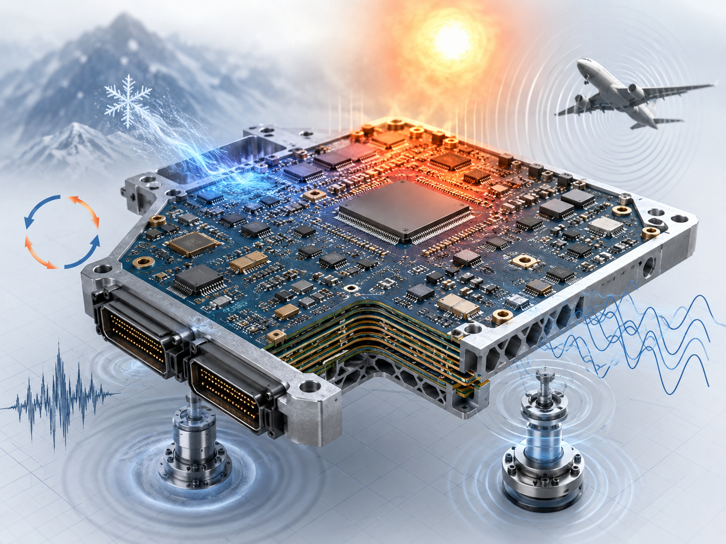
This matters because aerospace PCBs are often used in products where failure is expensive, difficult to repair, or safety-related. These boards may work in vibration, thermal cycling, altitude change, humidity, long service life, and strict maintenance environments.
Aerospace PCB testing requirements should be clear enough that a supplier can quote, manufacture, test, document, and ship the product without guessing. If a requirement is important, it should be written into the RFQ, drawing notes, purchase order, inspection plan, or quality agreement.
A useful principle is simple: do not ask only for “aerospace quality.” Ask for measurable standards, test methods, report formats, and acceptance rules.
Why Do Aerospace PCBs Need Stricter Testing?
Aerospace PCBs need stricter testing because their working environment is more demanding than many commercial electronic products. A standard PCB may pass basic manufacturing inspection, but that does not automatically make it suitable for aerospace PCB applications.
Aerospace and defense PCB assemblies may face:
- Wide temperature changes
- Thermal cycling and thermal stress
- Vibration and mechanical shock
- Humidity and contamination risk
- High altitude or low-pressure conditions
- Long operating life
- Dense routing and controlled impedance
- High current or high-frequency signals
- Limited repair access after installation
- Strict audit and documentation requirements
The risk is not always visible. A board can look good on the surface but still have hidden defects such as weak hole-wall plating, microvia cracks, resin voids, poor solder joints, insufficient annular ring, poor impedance control, or unverified material substitution.
For buyers, the key point is this: aerospace PCB testing is not only about finding defects. It is about proving that the board was built, inspected, and documented under controlled conditions.
That is why aerospace printed circuit boards often require more than a final electrical pass. They may need material certificates, process records, cross-section data, impedance coupon results, X-ray evidence, first article inspection, and controlled change records.
A high reliability PCB for aerospace is not defined by one inspection step. It is defined by the full control chain from material selection to final test report.
Which Standards Apply to Aerospace PCBs?
Several standards may apply to aerospace PCBs, depending on whether the project is a bare board, an assembled PCBA, a space-grade board, a defense program, or part of certified airborne electronic hardware.
The buyer should avoid writing one vague sentence such as “must meet aerospace standards.” Instead, the required standards should be separated by scope.
Common standard areas include:
| Scope | Commonly Used Standard or Requirement |
|---|---|
| Bare rigid PCB performance | IPC-6012, project class requirement |
| Space or military avionics rigid PCB | IPC-6012ES / IPC-6012FS if required |
| Bare board visual acceptability | IPC-A-600 |
| PCBA workmanship | IPC-A-610 Class 3 |
| Soldering process | J-STD-001 Class 3 |
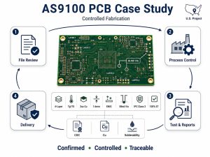
| Aerospace quality system | AS9100D |
| First article inspection | AS9102 when required |
| Environmental qualification | DO-160, MIL-STD-810, or project test plan |
| Military QML program | MIL-PRF-31032 when required |
| Airborne electronic hardware evidence | DO-254 / AC 20-152A context when applicable |
Not every aerospace PCB project needs every standard. A ground support device, an aircraft cabin control board, a UAV power module, a space-grade PCB, and a defense radar assembly may have different requirements.
For buyers, the practical rule is:
- Use IPC standards to define PCB and PCBA workmanship and acceptance.
- Use AS9100D to evaluate the supplier’s aerospace quality management system.
- Use AS9102 if first article inspection documentation is required.
- Use DO-160 or MIL-STD-810 when environmental qualification is required.
- Use MIL-PRF-31032 only when the program or customer specification requires that military QML framework.
- Use DO-254 / AC 20-152A when the PCB or PCBA evidence must support airborne electronic hardware certification and configuration control.
DO-254 and AC 20-152A are not normal PCB fabrication standards. They become relevant when the board-level manufacturing evidence supports hardware verification, configuration baseline, and certification records for airborne systems.
A clear standard stack reduces confusion. It also helps suppliers quote correctly instead of assuming a lower test or documentation level.
IPC Class 3, Class 3A or IPC-6012ES?
IPC Class 3, Class 3A, and IPC-6012ES are often discussed together, but they are not the same thing. Buyers should not treat them as interchangeable labels.
A simple way to understand them is:
- IPC Class 3
Used for high-performance electronic products where continued performance or performance-on-demand is critical. - IPC Class 3A / Class 3/A
Used when the customer or project requires a higher avionics or mission-critical expectation beyond normal Class 3 wording. It should be clearly defined by the applicable IPC document and procurement specification. - IPC-6012ES / IPC-6012FS
Addendum requirements for rigid printed boards used in space and military avionics applications. These add requirements or exceptions beyond normal IPC-6012 Class 3 requirements. - MIL-PRF-31032
A military performance specification tied to qualified printed board manufacturing programs when the contract requires it.
For a buyer, the safest wording is not “Class 3 only.” A better requirement should define:
- The IPC standard revision
- The product class
- Any applicable addendum
- Required tests
- Required reports
- Sampling or 100% inspection rules
- Traceability and change control
- Customer approval for deviations
A simple example of clearer wording is:
“Bare printed boards shall be manufactured and inspected to IPC-6012 Class 3 and IPC-A-600 Class 3, unless otherwise specified on the drawing. If the program requires space or military avionics requirements, IPC-6012ES or the applicable current addendum shall apply. Electrical testing, microsection, impedance verification, and deliverable reports shall follow the approved inspection plan.”
This wording is only a template. The final version should match the customer drawing, contract, program specification, and regulatory context.
The main point is simple: IPC Class 3 is often a starting point, not a complete aerospace PCB testing requirement by itself.
What Tests Are Required for Bare Boards?
Bare board testing focuses on the printed circuit board before component assembly. This is where the supplier verifies that the aerospace printed circuit board was fabricated correctly.
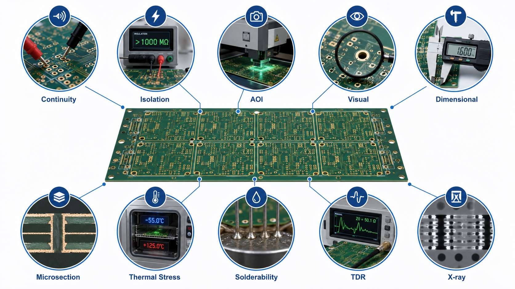
Common bare board tests include:
- Continuity test
Confirms that connected nets are electrically continuous. - Isolation test
Confirms that separated nets are not shorted. - AOI inspection
Checks opens, shorts, trace defects, annular ring issues, etching defects, and pattern errors. - Visual inspection
Reviews solder mask, surface finish, legend, edge quality, holes, scratches, contamination, and workmanship. - Dimensional inspection
Confirms board outline, hole size, slot size, thickness, registration, and critical tolerances. - Microsection inspection
Checks plated-through holes, via structure, copper thickness, lamination quality, resin recession, cracks, and voids. - Thermal stress test
Evaluates how plated holes and laminate structures survive soldering-related thermal stress. - Solderability test
Confirms that the surface finish can accept solder properly. - Impedance test
Uses coupons and TDR data to verify controlled impedance traces. - X-ray inspection
May be used for hidden structures such as blind vias, buried vias, HDI features, or internal alignment concerns.
For aerospace PCBs, the key question is not only “Can you test it?” The better question is:
“How will each test be performed, recorded, sampled, and delivered?”
For example, continuity and isolation may need 100% testing. Microsection may be performed by lot or coupon. Impedance may be verified through coupon testing. X-ray may be defined for specific hidden structures or high-risk areas.
If the inspection plan is not defined before production, the buyer may receive a board that technically passed the supplier’s internal process but does not meet the buyer’s acceptance expectations.
Is 100% Electrical Testing Required?
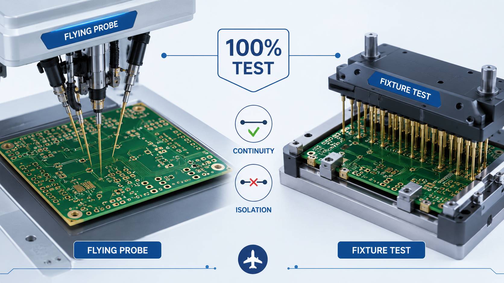
For aerospace PCBs, 100% electrical testing is commonly expected for bare board continuity and isolation. This is because an open or short circuit can create immediate functional failure, and sampling only a few boards may miss a critical defect.
Electrical testing usually checks:
- Net continuity
- Net isolation
- Opens
- Shorts
- Incorrect connections
- High-resistance defects when detectable by the test method
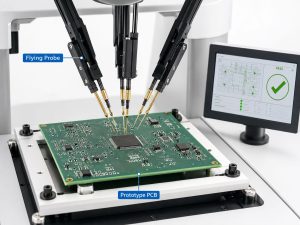
Both flying probe and fixture-based testing can be used. The correct method depends on volume, board complexity, lead time, cost, and test coverage.
A simple comparison is:
| Test Method | Best For | Buyer Concern |
|---|---|---|
| Flying probe | Prototype, small batch, complex low-volume boards | Slower for high volume |
| Bed-of-nails fixture | Medium to high volume | Fixture cost and setup time |
| Universal grid / fixture test | Repeat production | Coverage and fixture control |
The important point is not whether the supplier uses flying probe or bed-of-nails. The important point is whether the test covers the required netlist and whether every production board is tested when required.
Buyers should avoid vague wording such as:
“Supplier shall perform electrical test.”
A stronger requirement is:
“Supplier shall perform 100% netlist-based electrical testing for continuity and isolation on all delivered bare boards. Test records shall be retained and made available upon request. Sampling-only electrical testing is not acceptable unless approved in writing.”
This is the kind of wording that prevents later disputes.
For aerospace PCB assembly, electrical testing becomes broader. It may include ICT, flying probe assembly test, functional test, programming, boundary scan, or system-level test depending on the product.
When Are Microsection and TDR Tests Needed?
Microsection and TDR tests are needed when hidden manufacturing quality or controlled impedance must be verified. These tests are especially important for high reliability PCB for aerospace projects because many critical defects are not visible from the surface.
Microsection Testing
Microsection, also called cross-section analysis, cuts through a board or coupon to inspect internal structures under magnification.
It can verify:
- Hole-wall copper thickness
- Plating quality
- Barrel cracks
- Via fill quality
- Lamination defects
- Resin voids
- Inner layer registration
- Copper wrap
- Interconnect integrity
- Microvia structure
Microsection is usually not performed on every production board because it is destructive. Instead, it is commonly performed on test coupons, production panels, selected samples, first article lots, or lots defined by the inspection plan.
Buyers should define:
- When microsection is required
- Which coupon or sample is used
- What features must be measured
- What photos must be delivered
- What acceptance criteria applies
- What happens if the result fails
TDR and Impedance Testing
TDR testing is used to verify controlled impedance. It is common for aerospace printed circuit boards used in high-speed digital, RF, radar, communication, sensor, avionics, or defense electronics.
TDR testing can confirm:
- Single-ended impedance
- Differential impedance
- Coupon performance
- Stack-up consistency
- Transmission line control
A useful requirement may say:
“Controlled impedance shall be verified by TDR test on approved impedance coupons. Test data shall include target impedance, measured impedance, tolerance, coupon ID, lot number, and test date.”
TDR is not needed for every aerospace PCB. It is needed when the design includes controlled impedance requirements. If the drawing calls out 50Ω, 90Ω, 100Ω differential, or other controlled impedance values, the inspection plan should define how those values are verified.
In short, microsection proves hidden manufacturing quality. TDR proves controlled impedance performance. Both should be planned before production, not requested after boards are finished.
What Tests Apply to Aerospace PCB Assembly?
Aerospace PCB assembly testing applies after components are mounted. It is different from bare board testing. A PCB can pass fabrication inspection but still fail after soldering, cleaning, coating, programming, or functional operation.
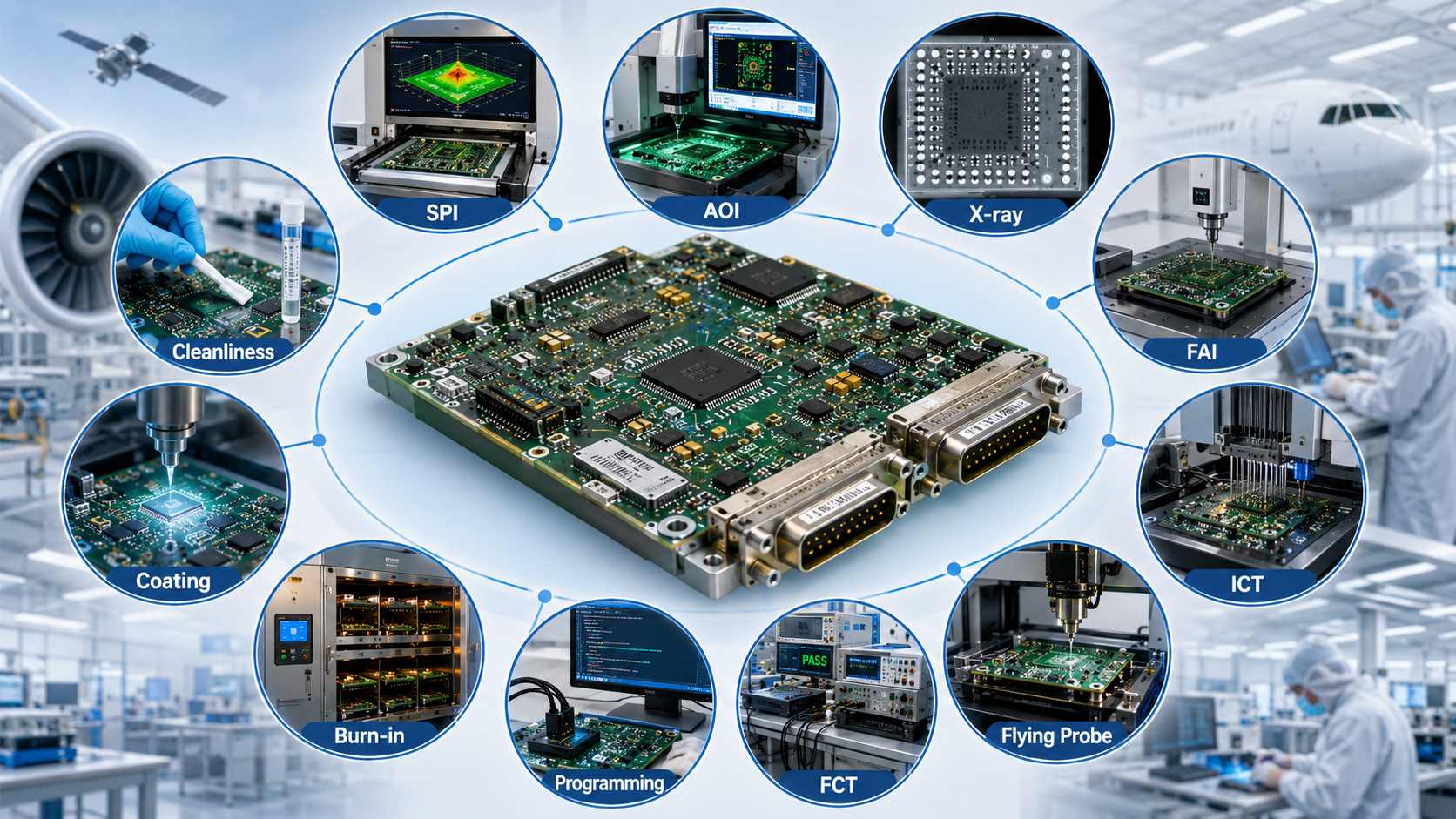
Common aerospace PCB assembly tests and inspections include:
- SPI
Checks solder paste volume, area, height, and alignment before reflow. - AOI
Checks component presence, polarity, solder joints, tombstoning, bridges, missing parts, and placement issues. - X-ray inspection
Used for BGA, QFN, bottom-terminated components, hidden joints, voids, and some high-reliability solder joints. - First article inspection
Confirms that the first assembled unit matches the approved BOM, drawing, placement, polarity, and workmanship requirements. - ICT
Checks assembled circuit electrical characteristics when test access is available. - Flying probe assembly test
Useful for low-volume or prototype aerospace PCB assembly where fixtures are not practical. - Functional test
Confirms that the PCBA performs the required electrical functions. - Programming and firmware verification
Applies when the assembly includes programmable devices. - Burn-in or aging test
May be used to screen early failures in selected projects. - Conformal coating inspection
Checks coverage, thickness, bubbles, masking, and contamination risk when coating is required. - Cleanliness or contamination testing
May be required for high-reliability or sensitive assemblies.
Aerospace & defense PCB assemblies often require tighter control of BOM, component sourcing, soldering profile, rework limits, operator training, and process records.
The buyer should define whether the supplier is responsible only for PCB manufacturing, or for full PCB assembly and manufacturing for defense and aerospace applications. This boundary changes the test plan, price, lead time, and deliverable documents.
For PCBA projects, “tested” should not be a general word. It should mean a defined test flow with clear acceptance criteria.
What Documents Should Suppliers Provide?
Documentation is what closes the loop in aerospace PCB testing requirements. Without documents, the buyer may know that the boards passed, but not how, when, by whom, under which lot, and against which acceptance rule.
A proper aerospace PCB delivery package may include:
- Certificate of Conformance
- Material certificates
- Laminate, prepreg, copper, solder mask, and surface finish batch records
- Surface finish certificate if required
- Electrical test report
- AOI inspection summary
- Dimensional inspection report
- Microsection photos and measured values
- Thermal stress or solderability test record
- Impedance coupon and TDR report
- X-ray report if applicable
- PCBA inspection report
- ICT or FCT report if applicable
- First Article Inspection report when required
- NCR record if any nonconformance occurred
- CAPA or SCAR response if required
- Approved deviation or concession record if any
- Change notification record
- Lot traceability or board serial number traceability
- Packing and handling records if specified
A stamped CoC alone is not enough for many aerospace PCB projects. It may be part of the package, but it does not replace test data, material traceability, or inspection evidence.
Buyers should decide the required traceability depth before ordering.
Common traceability levels include:
- Lot-level traceability
Links boards to a production lot and material batch records. - Panel-level traceability
Links a panel or production set to process records. - Board-level serial traceability
Links each delivered board or assembly to inspection, test, and production records.
Board-level traceability costs more, but it may be necessary for mission-critical or defense-related projects.
Change control is also important. The supplier should not change laminate, prepreg, copper foil, solder mask, surface finish, approved process, outside process, or critical component substitution without approval when the project requires controlled configuration.
A good document package protects both sides. It helps the buyer pass internal review, supplier audit, incoming inspection, and failure analysis if a field issue occurs.
FAQs About Aerospace PCB Testing Requirements
Are IPC Class 3 Requirements Enough for Aerospace PCBs?
IPC Class 3 is often a starting point, but it may not be enough by itself. Aerospace PCB projects may also require IPC-6012 addendums, AS9100D quality controls, first article inspection, traceability, environmental testing, and project-specific acceptance rules.
What Is the Difference Between IPC Class 3 and Class 3A?
IPC Class 3 is used for high-performance electronic products. Class 3A, often written in some contexts as Class 3/A, is associated with higher-reliability avionics or mission-critical expectations when specified by the applicable procurement document or IPC requirement. Buyers should not use the term casually. It should be tied to the correct standard and contract requirement.
Is IPC-6012ES Required for All Aerospace PCBs?
No. IPC-6012ES is not automatically required for every aerospace PCB. It is used when the program, drawing, contract, or customer specification requires space or military avionics addendum requirements. For many aerospace electronics, IPC Class 3 with additional project-specific testing may be used instead.
Does AS9100D Certify the PCB Itself?
No. AS9100D is a quality management system standard for aerospace organizations. It does not automatically certify that every PCB meets a specific technical requirement. Buyers still need to define the PCB standard, test plan, inspection reports, and acceptance criteria.
Should Aerospace PCBs Be 100% Electrically Tested?
For bare boards, 100% continuity and isolation testing is commonly expected for aerospace PCB projects. Sampling-only testing should not be used for critical electrical acceptance unless the buyer has formally approved it.
Is Flying Probe Testing Acceptable for Aerospace PCBs?
Flying probe testing can be acceptable when it provides the required netlist coverage and documented test results. The issue is not the machine type alone. The buyer should confirm test coverage, test limits, records, and whether every delivered board is tested.
When Is Microsection Required?
Microsection is needed when plated holes, vias, lamination quality, copper thickness, or hidden structures must be verified. It is commonly performed on coupons, production panels, first articles, or lots defined by the inspection plan.
When Is TDR Testing Required?
TDR testing is required when the PCB has controlled impedance requirements. It verifies that impedance coupons meet the target values and tolerances defined by the design.
Are Environmental Tests Part of PCB Testing?
Sometimes, but not always. Bare board factories usually handle fabrication-level tests. Environmental tests such as thermal cycling, vibration, shock, humidity, altitude, or DO-160 testing are often PCBA-level, box-level, or system-level requirements. Responsibility and cost should be defined in the RFQ or test plan.
What Documents Should I Request From an Aerospace PCB Supplier?
At minimum, request CoC, material certificates, electrical test evidence, inspection records, and traceability information. For high-reliability projects, also request microsection data, impedance reports, X-ray reports, FAI records, NCR/CAPA records, and change-control documentation when applicable.
How Can I Verify an AS9100 Certificate?
Buyers should verify AS9100 certification through the IAQG OASIS database instead of relying only on a PDF certificate sent by email. The certificate scope, site address, expiration date, and certification body should match the supplier being used.
Why Do Aerospace PCB Testing and Documentation Increase Cost?
The cost is higher because the supplier must perform more verification, maintain traceability, control materials, prepare records, manage audits, and sometimes support first article inspection or special process controls. The extra cost is mainly risk control, not only board fabrication.
To wrap up, Aerospace PCB testing requirements define the standards, inspections, test reports, traceability, and acceptance rules needed before aerospace printed circuit boards enter high-reliability applications.
For buyers, the key is to define the required tests clearly, including bare board electrical testing, microsection, impedance verification, aerospace PCB assembly inspection, and supplier documentation.
If you need aerospace PCB manufacturing, PCBA assembly, or DFM review, please feel free to send your Gerber files, BOM, stack-up, and project requirements to EBest Circuit (Best Technology) at sales@bestpcbs.com. As one of the experienced aerospace PCB manufacturers, we can help you review technical requirements, testing expectations, and production feasibility before manufacturing starts.