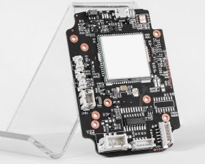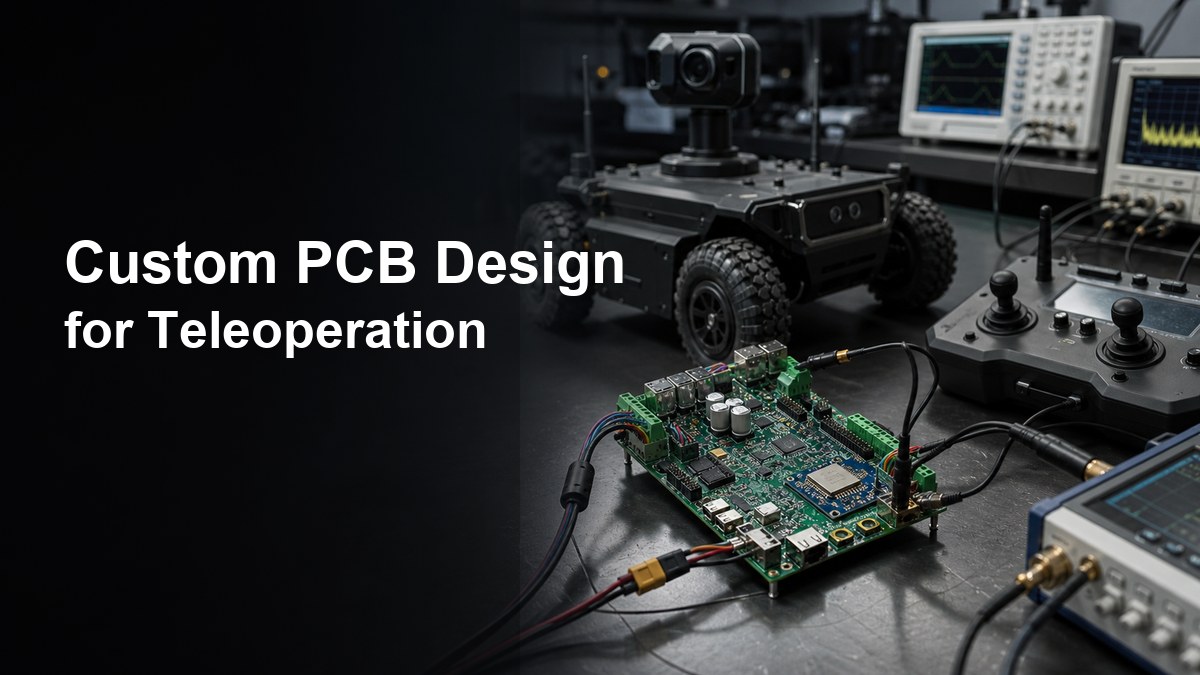
Custom PCB design for teleoperation should protect the remote-control link, motor-control power path, sensor feedback, test access and enclosure interface before the first prototype is ordered. A teleoperation PCB is not just a robot controller board. It carries the electronics that help an operator send commands, receive feedback and keep the machine predictable when wireless quality, vibration, load current or cable routing changes.
This guide is written for engineers and buyers preparing a custom PCB or PCBA for teleoperated robots, remote inspection equipment, mobile platforms, industrial manipulators, UAV ground systems, field-service devices or hazardous-area remote tools. It focuses on manufacturable PCB checks and RFQ readiness, not on robot-control algorithms.
What does custom PCB design for teleoperation need to control?
A teleoperation PCB needs to keep command input, feedback data, power conversion, motor drivers, sensors and safety-related I/O electrically separated enough to avoid unstable behavior. The design may include a microcontroller or processor, RF or wired communication module, camera or sensor inputs, encoder lines, motor-driver interfaces, battery or DC input, protection circuits and connectors to the robot body.
The board should be reviewed as a system. A clean schematic can still fail in the field if motor-current return paths disturb the receiver, if a camera interface sits beside a noisy regulator, or if a connector harness pulls against a weak solder joint. When wireless range, antenna routing or controlled impedance matters, compare the design against an RF PCB capability early instead of treating the radio section as a normal digital trace group.
| Teleoperation PCB area | Design check | Why it matters |
| Communication link | Antenna clearance, controlled routing, shielding, connector loss and RF module placement | Weak links create command delay, dropouts or unstable feedback |
| Power input | Battery/DC range, transient protection, regulator heat and local decoupling | Remote machines often see load surges and cable voltage drop |
| Motor and actuator paths | High-current loops, driver heat, return path and separation from sensors | Motor noise can reset logic or corrupt feedback signals |
| Sensor feedback | Encoder, camera, IMU, limit switch and telemetry routing | The operator needs reliable state information, not only command output |
| Production test | Programming access, test pads, fixture clearance and functional-test limits | A prototype that cannot be tested repeatably is not ready for volume |
How should latency and link reliability affect PCB layout?
PCB layout cannot remove all network delay, but it can reduce board-level causes of packet loss, noise coupling and unreliable command response. Teleoperation systems are sensitive to latency, jitter and communication dropouts, so the board should not add avoidable RF, grounding or power noise problems on top of the software and network layer.
Keep the antenna or RF module away from motor drivers, switching regulators, displays, dense cable bundles and metal enclosure walls unless the RF design intentionally accounts for them. Follow the module vendor’s keep-out and ground rules. If the design uses external antennas, review connector type, cable routing, mounting torque and enclosure feedthrough. If it uses wired control, check differential-pair routing, shielding, ESD protection and connector strain relief.
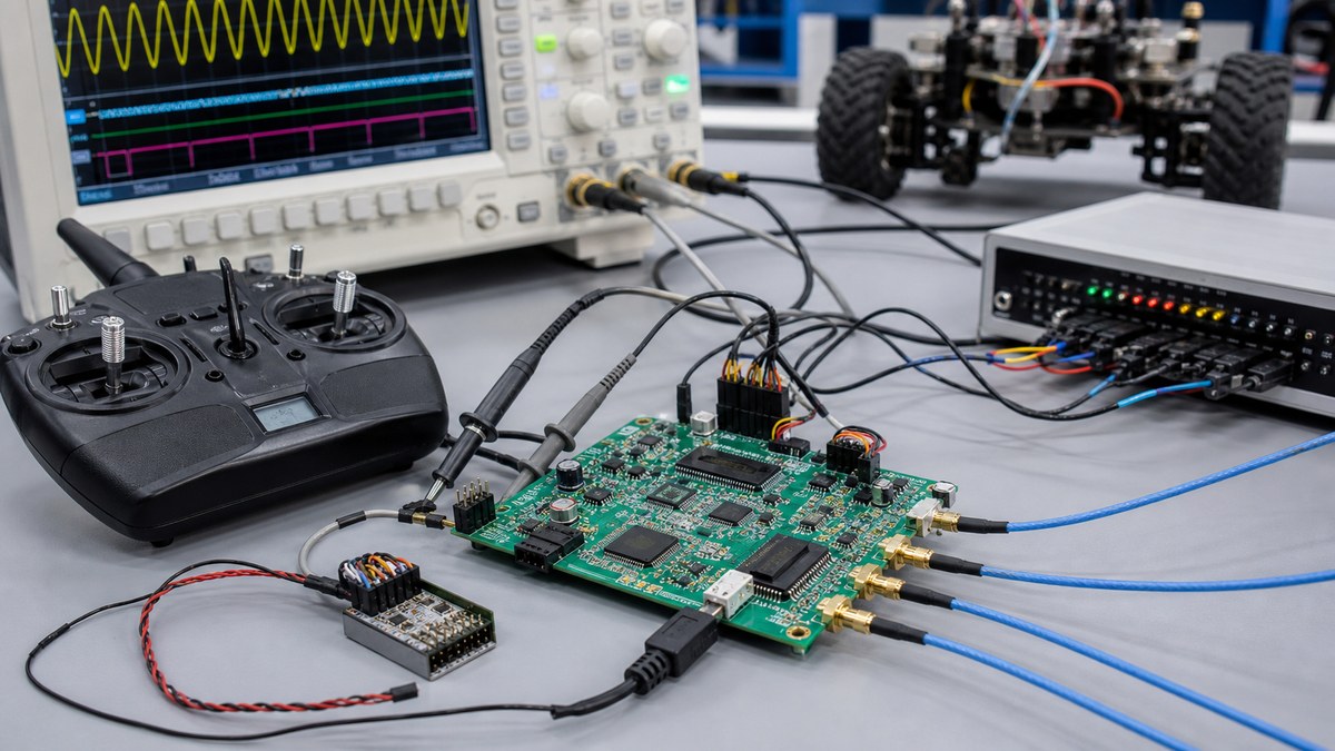
Do not bury the communication decision inside a generic PCB order. If the board includes RF, Ethernet, CAN, RS-485, USB, camera links or high-speed sensor data, the stackup, reference planes and connector placement should be part of the RFQ review. Related control-network design checks are also covered in the custom PCB design for industrial networks guide.
What power architecture should a remote robot controller use?
The power architecture should separate noisy actuator energy from logic, RF, sensors and safety I/O while still sharing a controlled grounding strategy. Teleoperated equipment often combines battery packs, DC input, motor drivers, servos, radios, cameras, lamps, heaters or brakes. Those loads should not all be treated as a single quiet supply problem.
Start by listing each rail, load current, startup sequence, allowable voltage range and heat source. Use local decoupling for processors, RF modules and sensors. Keep high-current switching loops short. Give motor-driver current a planned return path instead of letting it travel under the communication and sensor sections. If the design has high-current power electronics, heavier copper, thermal vias, wider pours or separate power boards may be needed; do not infer current capacity from trace width alone without reviewing temperature rise and board stackup.
How should motor noise, sensors and safety I/O be isolated?
Motor-control noise should be handled with placement, return-path control, filtering, connector separation and test access before the PCB is released. Teleoperation failures are often blamed on software, but random resets, lost encoder counts, noisy video, false limit-switch signals and unstable IMU readings can come from board-level coupling.
Place motor drivers and power switching away from sensitive analog, RF and feedback circuits. Use clear zones for encoder inputs, current sensing, limit switches, emergency-stop inputs and feedback buses. Add test points for rails, reset lines, communication status, actuator enable lines and critical sensors. For first builds, treat the project as a Prototype PCB Assembly job so assembly feedback, component alternates and functional-test access can be corrected before production.
Which PCB materials and stackups fit teleoperation boards?
Most teleoperation controller boards can start with FR4, but RF, high-speed, thermal, vibration and enclosure constraints may require stackup changes. A simple two-layer board may work for low-speed prototypes. A production controller with RF, cameras, processors, motor drivers and many connectors usually benefits from four or more layers because planes improve return paths, noise control and routing density.
Use high-frequency laminates or hybrid stackups only when the RF section, bandwidth or antenna design justifies the cost. For compact mobile equipment, board outline, connector height, stiffeners and mounting holes can be as important as material choice. If a remote unit needs a folded sensor harness, moving camera module or tight enclosure path, review whether flex or rigid-flex is more reliable than multiple cable connectors.
What should be checked before PCBA production?
Before PCBA production, verify that the board can be assembled, programmed, calibrated, inspected and tested under realistic command and load conditions. A teleoperation controller should not rely only on visual inspection or continuity testing. It needs checks that match how the remote machine behaves.
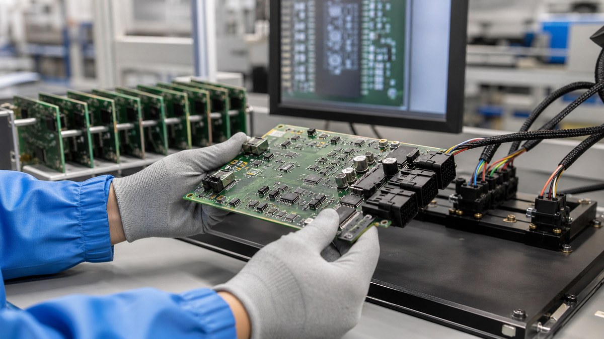
Define programming access, bootloader method, firmware version control, fixture pins, current-limit settings, communication checks and pass/fail criteria. Test the board with expected cable lengths, antenna placement and representative actuator loads when possible. Supplier-side PCB test equipment should be discussed before volume builds if the project needs fixture-based functional testing, not after the pilot run exposes missing pads.
How should connectors, harnesses and enclosures be planned?
Connectors and harnesses should be placed around assembly access, strain relief, service direction, cable noise and enclosure sealing. Teleoperated products often fail mechanically before they fail electrically: vibration loosens cables, operator ports get stressed, or enclosure walls block connector access.
Check connector locking style, mating cycles, wire gauge, cable bend radius, shield termination, gasket clearance and mounting screw access. Keep high-current motor wiring away from RF and sensor lines where possible. If the supplier is expected to deliver a tested controller inside a housing, discuss Box Build Assembly requirements such as harness routing, enclosure labels, final test and packing constraints.
RFQ checklist for custom teleoperation PCB design
A useful RFQ package should show the supplier the control architecture, RF or wired link, power budget, motor loads, enclosure constraints and test requirements. Without those details, the quote may cover board fabrication but miss the risks that make a teleoperation product hard to build.
- Gerber files, drill files, netlist, stackup, copper weight and controlled revision number.
- Schematic, BOM, approved alternates, centroid file and assembly drawing.
- Communication method: RF module, antenna type, Ethernet, CAN, RS-485, USB, camera link or mixed interfaces.
- Power input range, battery or DC supply notes, maximum load current and motor-driver information.
- Connector drawings, harness direction, enclosure model, mounting holes and height limits.
- Programming method, firmware loading requirement and board-level functional-test criteria.
- Environmental notes such as vibration, dust, humidity, outdoor use, heat, chemical exposure or service access.
- Any components that require sourcing approval, lifecycle review or controlled substitutes.
Teleoperation products often depend on RF modules, processors, connectors, motor drivers, sensors and power ICs that cannot be swapped casually. Involve Component Sourcing before the pilot build if approved alternates, lifecycle status or lead-time risk could change the control behavior.
Supplier questions buyers should ask
Supplier questions should force a real engineering review of link reliability, power integrity, assembly risk and test coverage. A low unit price is not useful if the first build cannot be programmed, calibrated or tested under load.
- Which layout areas are most likely to affect RF range, command response or feedback quality?
- Are the antenna, connector and enclosure positions compatible with the communication method?
- Do motor-driver current paths stay away from logic, RF and sensor feedback?
- Are all programming, debug and functional-test pads reachable after assembly?
- Which parts need approved alternates before production?
- Can the test fixture simulate command input, feedback output and representative load current?
- What should change before moving from engineering prototype to pilot production?
FAQ
What is custom PCB design for teleoperation?
Custom PCB design for teleoperation means designing a circuit board for remote command input, machine feedback, communication, power conversion, motor control, sensors and production test. The board must support predictable remote operation, not only basic robot movement.
Does teleoperation always need an RF PCB?
No. Some systems use wired Ethernet, CAN, RS-485 or tethered control. RF PCB review becomes important when the board includes antennas, wireless modules, controlled-impedance traces, coax connectors or tight enclosure constraints that affect radio performance.
What causes unstable teleoperation controller behavior?
Common board-level causes include motor noise coupling into logic, weak power rails, poor grounding, antenna placement problems, cable shielding mistakes, missing ESD protection, inaccessible test pads and firmware loading issues. Network software can also matter, but the PCB should not add preventable electrical faults.
How many layers should a teleoperation controller PCB use?
Simple prototypes may use two layers, but four or more layers are often safer when the board has RF, processors, motor drivers, cameras, sensors and many connectors. Planes help control return paths, EMI, routing density and power integrity.
What files are needed for a teleoperation PCB quote?
Send Gerber and drill files, schematic, BOM, centroid file, assembly drawing, stackup, enclosure notes, communication method, power budget, connector drawings and test requirements. Include firmware-loading and functional-test notes if the supplier will assemble the PCBA.
Conclusion
Custom PCB design for teleoperation should be reviewed around the full control path: command link, RF or wired interface, power rails, motor noise, sensor feedback, connectors, enclosure and test access. A supplier can quote more accurately when the RFQ includes the board files plus communication, power, harness and functional-test requirements. For a remote-control product, that preparation is often the difference between a board that only powers up and a controller that can be built, tested and improved repeatably.