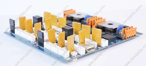
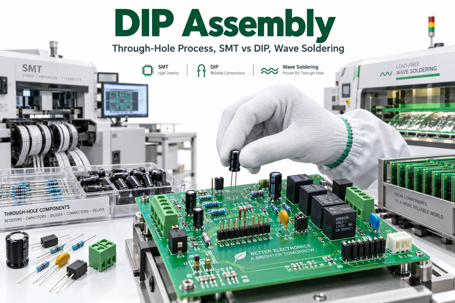
DIP assembly remains important even though most modern PCBAs rely heavily on surface-mount technology. Connectors, transformers, relays, terminal blocks, large capacitors, switches, and other mechanically demanding components are still frequently mounted through holes.
The terminology can be confusing because DIP and THT are not technically identical. DIP describes a package format, while THT describes a mounting method. In manufacturing practice, however, many PCBA factories use “DIP assembly” or “DIP line” as shorthand for the entire through-hole insertion and soldering stage.
Key Takeaways
- DIP assembly is commonly used in PCBA factories to describe the insertion and soldering of through-hole components. Strictly speaking, DIP means Dual In-Line Package, while THT means Through-Hole Technology.
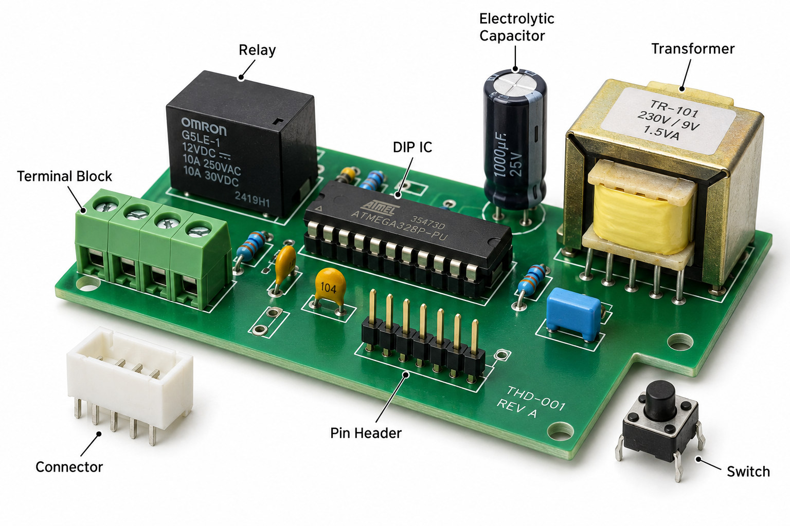
- A DIP assembly line may handle DIP ICs, connectors, relays, transformers, terminal blocks, electrolytic capacitors, headers, switches, and other leaded components.
- Modern PCBAs frequently combine SMT and DIP/THT assembly. Small, high-density components are mounted by SMT, while mechanically loaded or larger leaded parts use through-hole mounting.
- Through-hole components can be soldered by wave soldering, selective soldering, or hand soldering depending on board layout, production volume, component mix, and thermal constraints.
- PCB design directly affects DIP assembly quality. Finished hole size, annular ring, pad geometry, component spacing, solder accessibility, and bottom-side SMT placement all matter.
- Common DIP/THT defects include insufficient hole fill, solder bridges, cold joints, icicles, component tilt, incorrect polarity, and flux residue.
- Inspection and testing may include visual inspection, AOI, ICT, functional testing, programming, and X-ray when hidden structures justify it.
What Is DIP Assembly?
DIP assembly is commonly used in PCB manufacturing to describe the insertion and soldering of through-hole components after or alongside SMT assembly. Strictly, DIP stands for Dual In-Line Package, a package with two parallel rows of leads.
A traditional DIP IC is inserted through plated holes in the PCB and soldered on the opposite side. However, factory DIP lines usually process many other through-hole components that are not technically DIP packages.
Typical factory usage therefore includes:
- DIP ICs
- Connectors
- Relays
- Transformers
- Terminal blocks
- Headers
- Large electrolytic capacitors
- Switches
- Power components
For manufacturing discussions, it is useful to confirm whether “DIP assembly” means only actual DIP-packaged devices or the broader through-hole assembly process.
Is DIP Assembly the Same as Through-Hole Assembly?
Not exactly. DIP is a package style, while THT is a PCB mounting technology.
| Term | Meaning |
|---|---|
| DIP | Dual In-Line Package |
| THT | Through-Hole Technology |
| DIP component | A component with two parallel rows of leads |
| THT component | Any component whose leads pass through PCB holes |
| DIP assembly | Factory shorthand often used for THT assembly |
| DIP line | Through-hole insertion and soldering production line |
A DIP IC is normally a THT component, but many THT components are not DIP packages. A transformer with four leads, a terminal block, or a D-sub connector may all be processed on a DIP line even though none is a standard DIP package.
This distinction matters for engineering documentation. A BOM should specify the actual component package and mounting method rather than relying only on the term “DIP.”
What Components Are Commonly Used in DIP Assembly?
DIP assembly lines handle components that benefit from through-hole mounting or are not available in practical surface-mount formats.
A DIP switch assembly is one example of a through-hole control component that may be inserted and soldered on the same production line.
Common examples include:
- DIP ICs
- DIP switches
- Pin headers
- Board-to-wire connectors
- D-sub connectors
- Terminal blocks
- Relays
- Transformers
- Large electrolytic capacitors
- Power resistors
- LEDs
- Potentiometers
- Mechanical switches
- High-force connectors
Through-hole mounting is often selected when the component experiences mechanical loading. Connector insertion and removal, cable forces, relay mass, or transformer weight can make lead-through-hole retention useful.
This does not mean every THT component is automatically more electrically capable or more reliable than an SMT equivalent. The correct choice depends on the component, current, heat, mechanical load, solder-joint design, and operating environment.
What Equipment Is Used on a DIP Assembly Line?
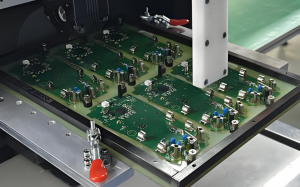
A DIP assembly line can combine manual workstations, automatic insertion equipment, soldering systems, inspection, and testing.
Typical equipment includes:
- Lead-forming machines
- Axial-component insertion machines
- Radial-component insertion machines
- Odd-form insertion machines
- Manual insertion conveyors
- Component clinching equipment
- Fluxing and preheating systems
- Wave soldering machines
- Selective soldering machines
- Lead-trimming equipment
- AOI systems
- Repair stations
- ICT fixtures
- Functional test equipment
The exact configuration depends on volume and component mix. A high-volume appliance board with many repetitive axial parts may justify automatic insertion, while a low-volume industrial assembly with large connectors may rely more heavily on manual insertion.
At EBest Circuit, mixed-technology PCBA projects can be reviewed for SMT, THT insertion, wave soldering, selective soldering, and testing requirements before the production route is finalized.
What Is the DIP Assembly Process?
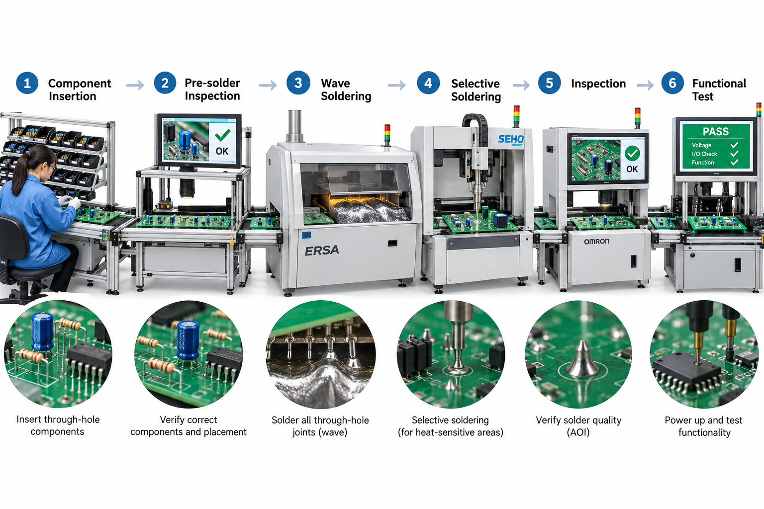
A typical DIP assembly process starts after component and PCB verification and ends with inspection and electrical testing.
- Material and BOM verification. Confirm component part number, polarity, package, lead condition, and quantity.
- Lead forming and preparation. Bend, cut, or form leads where required.
- Manual or automatic insertion. Insert the component leads through the correct PCB holes.
- Pre-solder inspection. Check orientation, polarity, seating, and component location.
- Fluxing and preheating. Prepare the solder side for stable wetting.
- Wave, selective, or manual soldering. Form the through-hole solder joints.
- Lead trimming, touch-up, and cleaning. Remove excessive lead length and repair defects where necessary.
- Inspection and testing. Check solder joints and verify electrical function.
The process route can change when the PCB contains both SMT and THT components. Component thermal sensitivity, bottom-side SMT parts, solder pallets, and selective-solder nozzle access all influence the final sequence.
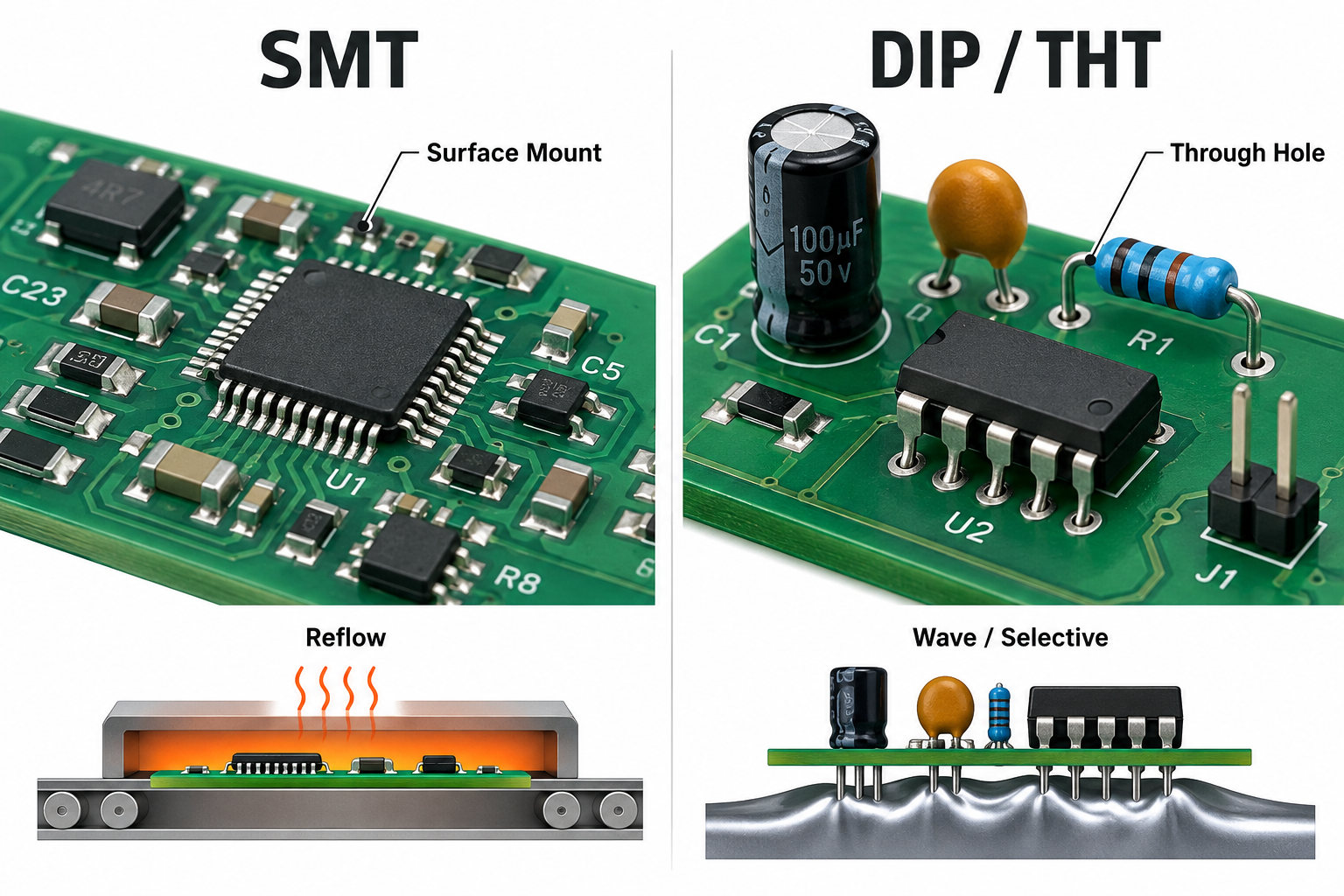
SMT vs DIP Assembly: What Is the Difference?
SMT places components directly on PCB surface pads, while DIP/THT assembly passes component leads through drilled holes.
| Factor | SMT | DIP / THT |
|---|---|---|
| Mounting | On PCB surface | Leads through PCB holes |
| Typical soldering | Reflow | Wave, selective, or hand soldering |
| Component density | Higher | Lower |
| Hole requirement | Usually no component holes | Plated through holes required |
| Automation | Highly automated | Manual and automatic mix |
| Typical components | BGA, QFN, SMD passives | Connectors, relays, transformers, DIP ICs |
| Mechanical retention | Mainly solder-pad attachment | Lead passes through board |
| Board area | Usually lower | Usually higher |
SMT is generally preferred for dense digital electronics because components and pads occupy less area. It also supports high-speed automated placement.
DIP/THT remains useful where component size, mechanical stress, connector retention, legacy parts, or specific power components make through-hole mounting practical.
The two technologies are therefore complementary rather than competing solutions.
How Are SMT and DIP Combined on the Same PCBA?
Mixed SMT and DIP assembly is common in industrial, automotive-control, power, appliance, medical, and communication electronics.
In production planning, SMT and DIP assembly steps are sequenced to protect components and maintain solder access. An SMT DIP assembly route normally completes reflow before through-hole insertion and wave, selective, or hand soldering.
A typical mixed process can be:
Solder paste printing → SMT placement → reflow → AOI → THT insertion → wave/selective soldering → inspection → functional test
The SMT stage normally installs ICs, resistors, capacitors, QFN/BGA packages, small diodes, and small transistors. The THT stage may then install connectors, relays, transformers, terminal blocks, large capacitors, and mechanical switches.
SMT is often completed first because reflow can process hundreds or thousands of surface joints in one controlled thermal cycle. The through-hole parts are then inserted and soldered using a process compatible with the already assembled board.
The exact sequence is not universal. Bottom-side SMT components, wave-solder pallets, component temperature limits, and board accessibility can require a different manufacturing route.
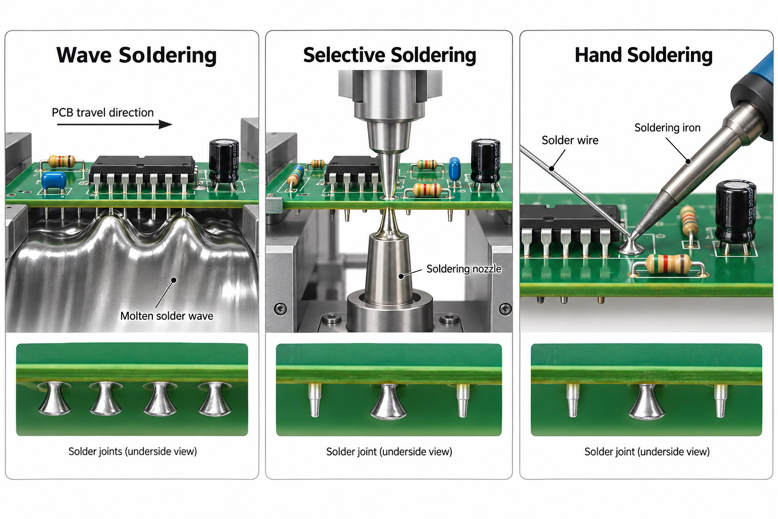
Wave vs Selective vs Hand Soldering: Which Is Used for DIP Assembly?
The soldering method should be selected from PCB layout, joint count, component density, production volume, and thermal restrictions.
| Method | Best Fit | Main Limitation |
|---|---|---|
| Wave soldering | Many THT joints, higher-volume boards | Large solder-side area exposed to the wave |
| Selective soldering | Mixed SMT/THT and localized joints | Slower and more process-specific |
| Hand soldering | Prototypes, rework, odd-form parts | Labor and operator dependent |
Wave soldering passes the solder side over a controlled wave of molten solder. It is efficient when many through-hole joints can be soldered in one operation.
Selective soldering uses a programmable nozzle or localized soldering system. It is especially useful when only certain THT joints should contact molten solder or when bottom-side SMT parts limit full-wave exposure.
Hand soldering remains useful for prototypes, low-volume builds, rework, unusual connectors, and components that cannot be handled efficiently by wave or selective equipment.
No method is inherently best for every board. The correct process depends on the layout and manufacturing quantity.
What PCB Design Rules Matter for DIP Assembly?
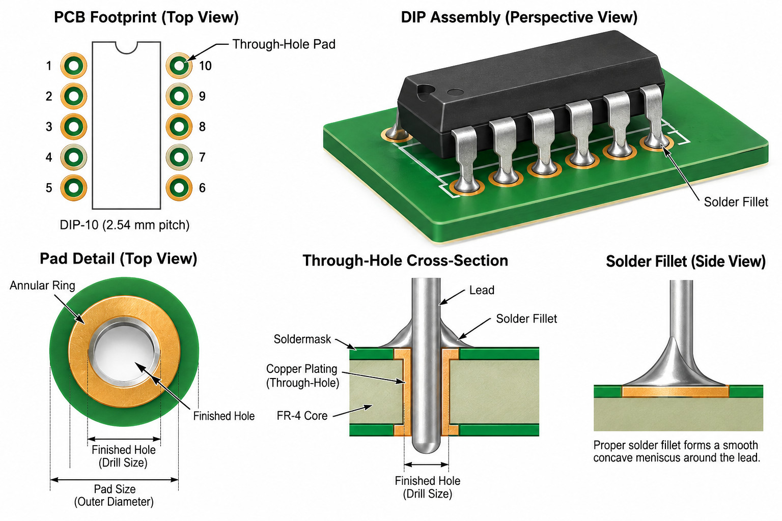
DIP/THT assembly quality depends heavily on PCB hole and pad design. A schematic can be correct while the through-hole assembly remains difficult or unreliable because of poor footprint geometry.
Important design items include:
- Finished hole diameter
- Component lead diameter
- Hole-to-lead clearance
- Annular ring
- Pad diameter
- Copper thickness
- Thermal-relief design
- Component spacing
- Wave-solder direction
- Solder shadowing
- Selective-solder nozzle access
- Bottom-side SMT clearance
- Component height
- Pin 1 and polarity marking
- Lead protrusion after soldering
The finished hole must provide enough clearance for insertion and solder flow without becoming excessively large. Too little clearance can make insertion difficult and restrict solder movement, while excessive clearance reduces mechanical support and can complicate hole filling.
Large copper planes can also remove heat from a through-hole pad. Thermal relief may be needed to obtain stable soldering temperature without excessive dwell time.
For selective soldering, nearby components, board edges, fixture features, and nozzle size must also be considered during layout rather than after the PCB is fabricated.
What Defects Are Common in DIP Assembly?
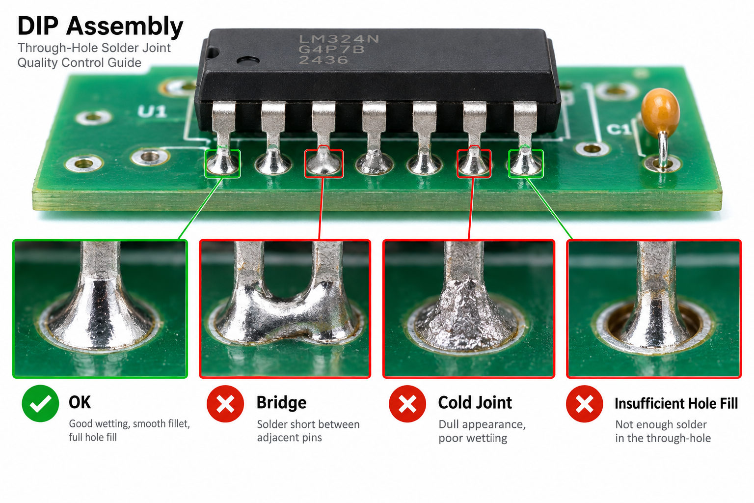
Most DIP/THT defects are related to component insertion, solder wetting, hole filling, temperature, or handling.
Common defects include:
- Insufficient hole fill
- Cold solder joints
- Solder bridging
- Solder icicles
- Excess solder
- Solder voids
- Component tilt
- Incorrect polarity
- Wrong component location
- Missing component
- Lifted pad
- Barrel damage
- Excessive lead protrusion
- Flux residue
Insufficient hole fill can occur when the solder does not rise adequately through the plated hole. Hole geometry, board thickness, copper planes, flux activity, preheat, solder temperature, and component lead condition can all contribute.
Solder bridging occurs when adjacent joints are unintentionally connected. It can be influenced by pad spacing, lead spacing, solderability, conveyor direction, solder conditions, and component geometry.
Inspection should therefore identify the defect and its process cause rather than treating every poor joint as an operator issue.
How Is DIP Assembly Inspected and Tested?
DIP assembly quality control should verify both component installation and solder-joint performance.
Typical controls include:
- Incoming component inspection
- First-article inspection
- Pre-wave insertion inspection
- Visual solder-joint inspection
- AOI where applicable
- X-ray when hidden geometry justifies it
- ICT
- Functional testing
- Firmware programming
- Burn-in when specified
Before soldering, inspectors can check component value, orientation, polarity, seating height, missing parts, and lead position.
After soldering, inspection focuses on joint wetting, hole fill, bridges, excess solder, damaged pads, and lead protrusion.
X-ray is not automatically required for every DIP assembly. Most conventional through-hole joints are visible from the solder side, so visual inspection, AOI, ICT, and functional testing are often more useful. X-ray should be applied when hidden geometry or specific reliability requirements justify it.
EBest Circuit supports SPI, AOI, X-ray, ICT, and functional testing according to the actual assembly and inspection needs of the project.
When Should Engineers Choose DIP/THT Instead of SMT?
DIP/THT is most useful when the component or product needs mechanical retention, specific component availability, or a mounting format that SMT cannot provide efficiently.
Typical examples include:
- Connectors subject to repeated mating forces
- Terminal blocks with cable loads
- Heavy transformers
- Large relays
- Mechanical switches
- High-force controls
- Socketed or serviceable ICs
- Legacy components
- Certain large power components
The selection should not be based on a rule that “THT is always stronger” or “SMT is always better.”
Instead, consider mechanical load, component mass, current requirement, thermal environment, available package type, PCB area, assembly volume, automation level, rework requirements, and lifecycle/sourcing.
A mixed approach is often the most practical solution: SMT for density and automation, THT for components that benefit from mechanical through-board attachment.
What Should Buyers Include in a DIP Assembly RFQ?
A DIP assembly quotation should define the bare PCB, through-hole components, assembly process, and acceptance criteria.
| Requirement | Why It Matters |
|---|---|
| Gerber / ODB++ | PCB fabrication data |
| BOM | Component identification |
| Pick-and-place / insertion data | Component location |
| Assembly drawing | Orientation and polarity |
| THT component datasheets | Lead and package geometry |
| Solder alloy | Process and temperature selection |
| Wave/selective requirement | Production routing |
| IPC class | Acceptance criteria |
| Test specification | ICT/FCT scope |
| Quantity | Manual vs automated process planning |
Also specify where applicable:
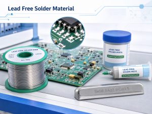
- Lead-free or SnPb requirement
- Conformal coating
- Programming
- Burn-in
- Potting
- Cleaning requirements
- Box build
- Special connector insertion
- Customer-supplied components
If the soldering method has not yet been selected, the manufacturer can review the PCB layout and component mix before determining whether wave, selective, or manual soldering is most appropriate.
FAQ About DIP Assembly
1. What does DIP stand for in electronics?
DIP stands for Dual In-Line Package, a package with two parallel rows of component leads.
2. Is DIP assembly the same as through-hole assembly?
Not strictly. DIP is a package type, while THT is a mounting technology. However, many PCBA factories use “DIP assembly” as shorthand for their through-hole production stage.
3. What is a DIP assembly line?
A DIP assembly line handles through-hole component preparation, insertion, soldering, inspection, repair, and testing.
4. What is the difference between SMT and DIP assembly?
SMT mounts components directly onto PCB surface pads and typically uses reflow soldering. DIP/THT inserts component leads through drilled holes and normally uses wave, selective, or hand soldering.
5. Can SMT and DIP components be used on the same PCB?
Yes. Mixed SMT and THT assembly is very common, especially on industrial, power, automotive, appliance, and communication boards.
6. Is wave soldering required for every DIP assembly?
No. Selective soldering or hand soldering may be more appropriate depending on the board layout, production quantity, bottom-side SMT components, and component mix.
DIP assembly remains an important part of modern PCBA production because many connectors, relays, transformers, terminal blocks, switches, and other components still benefit from through-hole mounting. The key is to treat DIP/THT requirements as part of the complete PCB and assembly design rather than as a separate manual process added at the end.
For a mixed SMT and DIP assembly project, send your Gerber files, BOM, pick-and-place data, assembly drawings, THT component datasheets, soldering requirements, and test specification to sales@bestpcbs.com for DFM and PCBA review.