An SMD capacitor is a surface-mount capacitor soldered directly onto PCB pads. It is widely used in modern PCB assembly because it saves space, supports automated SMT production, and works well in compact electronic circuits.
However, choosing or replacing an SMD capacitor is not always as simple as matching one number. You may need to check its capacitance value, package size, voltage rating, dielectric type, polarity, footprint, and circuit function. Many small ceramic SMD capacitors also have no printed marking, which makes identification more difficult.
This guide explains SMD capacitor values, codes, sizes, polarity, types, selection rules, and testing methods in a practical way.

What Is an SMD Capacitor?
An SMD capacitor is a capacitor designed for surface mount technology. Instead of using long leads that pass through PCB holes, it is mounted directly on solder pads on the PCB surface.
A typical SMD capacitor has:
- A compact body
- Metal terminations or leads
- A capacitance value
- A voltage rating
- A dielectric material
- A package size
- A tolerance and temperature rating
The most common SMD capacitor is the MLCC, or multilayer ceramic capacitor. MLCCs are widely used because they are small, low-cost, non-polarized, and suitable for automated SMT assembly.
SMD capacitors are commonly used for:
- Decoupling
- Bypassing
- Filtering
- Coupling
- Timing
- Noise suppression
- Power rail stabilization
- RF tuning
- Signal conditioning
In simple terms, an SMD capacitor stores and releases electrical charge in a compact package. It helps circuits operate more stably while reducing PCB space.
What Does SMD Mean on a Capacitor?
SMD means Surface Mount Device. On a capacitor, it means the component is made for surface mounting on a PCB.
SMD does not define the capacitance value, voltage rating, dielectric material, or polarity. It only describes the mounting style.
An SMD capacitor can be:
- Ceramic
- Tantalum
- Aluminum electrolytic
- Polymer
- Film
- Specialty capacitor
For example, a 100 nF ceramic capacitor in a 0603 package and a 100 µF SMD electrolytic capacitor are both SMD capacitors. But they are used in different circuits and follow different selection rules.
So when you see “SMD capacitor,” the next questions should be:
- What is the capacitance value?
- What is the package size?
- What is the voltage rating?
- Is it polarized?
- What dielectric or capacitor type is used?
- What is its function in the circuit?
What Is the Value of an SMD Capacitor?
The value of an SMD capacitor is its capacitance. It tells how much electrical charge the capacitor can store. Capacitance is usually measured in pF, nF, or µF.
Different units are used because capacitor values cover a wide range:
- Small capacitance values are usually written in pF
- Medium capacitance values are often written in nF
- Larger capacitance values are usually written in µF
A simple way to understand the units is:
| Value Range | Common Unit | Typical Example |
|---|---|---|
| Small capacitance | pF | 10 pF, 100 pF |
| Medium capacitance | nF | 1 nF, 10 nF, 100 nF |
| Large capacitance | µF | 1 µF, 10 µF, 47 µF |
Common SMD capacitor values include:
| Common Value | Also Written As | Typical Use |
|---|---|---|
| 10 pF | 0.01 nF | RF circuits and timing circuits |
| 100 pF | 0.1 nF | Signal filtering |
| 1 nF | 1,000 pF / 0.001 µF | Noise filtering |
| 10 nF | 0.01 µF | Coupling or filtering |
| 100 nF | 0.1 µF | IC decoupling |
| 1 µF | 1,000 nF | Power rail stabilization |
| 10 µF | 10,000 nF | Power rail support |
| 47 µF or higher | 47,000 nF or higher | Power input filtering and energy storage |
A very common SMD capacitor value is 100 nF, also written as 0.1 µF. It is often placed near IC power pins to reduce voltage noise.
The correct value depends on the circuit function. A decoupling capacitor, RF capacitor, timing capacitor, coupling capacitor, and power input capacitor may all need different values, even if they look similar on the PCB.
How to Identify an SMD Capacitor on a PCB?
Identifying an SMD capacitor on a PCB depends on its size, package, marking, and location. Larger SMD capacitors may have printed markings, while small ceramic capacitors are often blank.
You can identify an SMD capacitor by checking:
- PCB reference designator
Capacitors are usually marked as C1, C2, C10, C101, or similar on the PCB silkscreen. - Component shape
MLCCs are usually small rectangular blocks. Tantalum and electrolytic capacitors are often larger and may show polarity marks. - Color and body style
Ceramic capacitors are often beige, brown, gray, or off-white. Tantalum capacitors may be yellow or black. Aluminum electrolytic capacitors are often cylindrical. - Marking or code
Some larger SMD capacitors show capacitance, voltage, polarity, or manufacturer codes. - Circuit location
A capacitor near an IC power pin is often used for decoupling. A capacitor near a power input may be used for filtering or bulk energy storage. - BOM and schematic
The most reliable source is the BOM, schematic, assembly drawing, or original component part number. - Measurement
An LCR meter can help measure capacitance, but in-circuit measurement may be affected by other components.
Do not rely only on color or size. Two MLCCs with the same package and color may have completely different values. For repair or replacement, confirm the value through design files, circuit function, markings, or measurement after removal.
How to Read SMD Capacitor Codes and Markings?
SMD capacitor codes depend on the capacitor type. Some SMD capacitors have printed codes, but many small MLCCs do not.
Most small ceramic SMD capacitors in 0201, 0402, 0603, and 0805 packages are unmarked. Their values are usually confirmed by the BOM, reel label, schematic, or measurement.
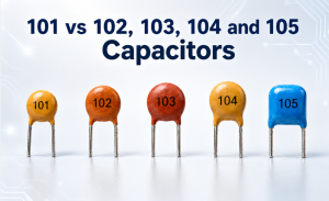
When a capacitor uses a three-digit code, the first two digits are the base number, and the third digit tells how many zeros are added in pF.
| Code | Value | Also Written As |
|---|---|---|
| 101 | 100 pF | 0.1 nF |
| 102 | 1 nF | 1,000 pF |
| 103 | 10 nF | 0.01 µF |
| 104 | 100 nF | 0.1 µF |
| 105 | 1 µF | 1,000 nF |
| 106 | 10 µF | 10,000 nF |
Example:
104 = 10 + 4 zeros = 100,000 pF = 100 nF = 0.1 µF
For tantalum and aluminum electrolytic SMD capacitors, markings may show:
- Capacitance
- Voltage rating
- Polarity
- Manufacturer code
- Series code
- Date or lot code
For example, a capacitor marked “10 16V” may indicate 10 µF and 16V, but marking rules vary by manufacturer. Always confirm with the datasheet when the marking is unclear.
What Are Common SMD Capacitor Sizes?
SMD capacitor size refers to the physical package dimensions of the component. The package size affects PCB space, capacitance range, voltage rating, assembly difficulty, inspection, rework, and reliability.
Common SMD capacitor sizes include 0201, 0402, 0603, 0805, 1206, 1210, 1812, and 2220.
| Imperial Code | Metric Code | Approx. Dimensions (mm) | Approx. Dimensions (inch) | Common Use |
|---|---|---|---|---|
| 0201 | 0603 | 0.6 × 0.3 | 0.024 × 0.012 | Ultra-compact modules |
| 0402 | 1005 | 1.0 × 0.5 | 0.040 × 0.020 | Mobile devices and compact PCBA |
| 0603 | 1608 | 1.6 × 0.8 | 0.063 × 0.031 | General electronics |
| 0805 | 2012 | 2.0 × 1.25 | 0.079 × 0.049 | Industrial boards and prototypes |
| 1206 | 3216 | 3.2 × 1.6 | 0.126 × 0.063 | Power rails and larger capacitance |
| 1210 | 3225 | 3.2 × 2.5 | 0.126 × 0.098 | Higher capacitance or voltage |
| 1812 | 4532 | 4.5 × 3.2 | 0.177 × 0.126 | Higher voltage or power circuits |
| 2220 | 5750 | 5.7 × 5.0 | 0.224 × 0.197 | High capacitance or special use |
Small packages save space, but they can be harder to assemble, inspect, and rework. They may also have weaker real capacitance performance under DC bias.
Larger packages need more PCB area, but they may support higher capacitance, higher voltage, better solder joint visibility, and easier repair.
For example, a 10 µF ceramic capacitor in a very small package may lose a large part of its effective capacitance under DC bias. A larger package or higher voltage rating may perform better in real operation.

SMD Capacitor Size Chart and Footprint Dimensions
An SMD capacitor package and an SMD capacitor footprint are related, but they are not the same.
- Package size means the physical size of the capacitor body.
- Footprint means the PCB solder pad pattern used to mount the capacitor.
- Land pattern is another term for the PCB pad design.
- Pad gap affects alignment and soldering result.
- Pad size affects solder wetting, fillet shape, and inspection.
A good footprint should support:
- Stable pick-and-place alignment
- Proper solder joint formation
- Enough solder wetting area
- Reliable reflow soldering
- Lower tombstoning risk
- Manufacturable spacing from nearby parts
- Easier inspection and rework when needed
Footprint problems can cause:
- Tombstoning
- Component skew
- Open solder joints
- Weak solder joints
- Solder beading
- Poor wetting
- Difficult inspection
Do not copy a footprint randomly from another design. The correct land pattern may depend on the capacitor package, manufacturer recommendation, solder paste thickness, reflow process, PCB surface finish, assembly capability, and inspection requirement.
For reliable PCBA manufacturing, confirm both the SMD capacitor package and the recommended footprint before finalizing the PCB layout.
What Are the Main Types of SMD Capacitors?
SMD capacitors are available in several types. Each type has different electrical behavior, size, cost, polarity, voltage range, and application area.
The main types include:
- SMD ceramic capacitor / MLCC
- SMD tantalum capacitor
- SMD aluminum electrolytic capacitor
- SMD polymer capacitor
- SMD film capacitor
SMD Ceramic Capacitor
SMD ceramic capacitors are the most common type. Most are MLCCs.
They are widely used because they are:
- Small
- Low-cost
- Non-polarized
- Good for high-frequency circuits
- Suitable for automated SMT assembly
- Available in many package sizes
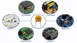
Common applications include decoupling, bypassing, filtering, RF circuits, and general PCB design.
The key point to remember is DC bias. High-capacitance MLCCs may lose effective capacitance when voltage is applied, especially in small packages.
SMD Tantalum Capacitor
SMD tantalum capacitors are often used when higher capacitance density and stable capacitance are needed.
They are commonly used in:
- Power rails
- Filtering circuits
- Compact power designs
- Some industrial and communication electronics
They are polarized, so correct orientation is required. Reverse voltage or surge current may cause failure, so voltage derating is important.
SMD Aluminum Electrolytic Capacitor
SMD aluminum electrolytic capacitors are usually used for larger capacitance values.
They are common in:
- Power input filtering
- Bulk energy storage
- Power supply circuits
- Industrial electronics
They are polarized and usually larger than ceramic capacitors. ESR, ripple current, temperature, and lifetime should be checked before selection.
SMD Polymer Capacitor
SMD polymer capacitors are used when the circuit needs low ESR and better ripple current performance.
They are useful for:
- DC-DC converters
- Power rails
- High-current power circuits
- Low-ESR filtering
They usually cost more than standard electrolytic capacitors, but they can provide better power performance.
SMD Film Capacitor
SMD film capacitors are less common than MLCCs, but they are useful in circuits that need stability, low loss, or pulse performance.
They may be used in:
- Signal circuits
- Timing circuits
- Pulse circuits
- Selected power applications
They are often larger than ceramic capacitors, so they are not used everywhere.

Are SMD Capacitors Polarized?
Some SMD capacitors are polarized, and some are non-polarized.
Most SMD ceramic capacitors are non-polarized. They can usually be installed in either direction because they do not have positive and negative terminals.
Common non-polarized types include:
- MLCC ceramic capacitors
- Some film capacitors
- Some specialty capacitors
Tantalum, aluminum electrolytic, and many polymer capacitors are polarized. They must be installed in the correct direction.
Common polarized types include:
- SMD tantalum capacitor
- SMD aluminum electrolytic capacitor
- SMD polymer capacitor
If a polarized capacitor is installed backwards, it may fail, heat up, leak, short, or damage the circuit.
You can check polarity by looking for:
- Plus mark
- Stripe mark
- Beveled edge
- Printed polarity symbol
- PCB silkscreen
- Datasheet orientation
- Package style
Be careful because polarity markings differ by capacitor type. Tantalum capacitors often mark the positive side, while aluminum electrolytic capacitors often mark the negative side. If the marking is unclear, check the datasheet before assembly.
How to Choose SMD Capacitor Value, Voltage and Package?
Choosing the right SMD capacitor requires more than matching the capacitance value. A suitable capacitor should match the electrical requirement, package size, footprint, assembly process, and working environment.
Check these points before selection:
- Capacitance value
Select the required pF, nF, or µF value based on the circuit function. - Voltage rating
Choose a voltage rating higher than the working voltage. Do not operate the capacitor too close to its rated limit. - Package size
Match the package with PCB space, capacitance range, voltage rating, and assembly capability. - Dielectric type
C0G/NP0, X7R, X5R, and other dielectrics behave differently. Use stable dielectrics for precision or temperature-sensitive circuits. - DC bias performance
MLCC capacitance may drop under applied DC voltage. Check the datasheet curve when the capacitor is used on a DC power rail. - ESR and ripple current
These are important for power supply, converter, and filtering applications. - Polarity
Confirm whether the capacitor is polarized before assembly or replacement. - Footprint
Make sure the package matches the PCB pad pattern. - Temperature range
Match the capacitor to the product operating environment. - Availability
For production, check supply stability and possible alternative parts.
Common mistakes include:
- Choosing only by capacitance
- Ignoring DC bias
- Using too low a voltage rating
- Confusing polarized and non-polarized capacitors
- Using the wrong footprint
- Replacing a capacitor only by size
- Ignoring temperature and lifetime requirements
A better selection process is to check the BOM, schematic, datasheet, layout footprint, assembly process, and application conditions together.
For PCBA projects, BOM review before production can help confirm capacitor package, voltage rating, polarity, footprint, sourcing risk, and possible alternatives.
How to Test a Bad or Shorted SMD Capacitor?
Testing an SMD capacitor depends on whether it is still mounted on the PCB or removed from the circuit. In-circuit testing can be misleading because other components may be connected in parallel.
Common signs of a bad SMD capacitor include:
- Short circuit
- Burn marks
- Cracking
- Leakage
- Bulging on electrolytic types
- Low capacitance
- High ESR
- Power rail short
- Circuit instability
- Device not powering on
A practical testing process:
- Start with visual inspection
Check for cracks, burns, discoloration, leakage, lifted pads, or broken solder joints. - Check for short circuit
Use a multimeter in resistance or continuity mode. A very low resistance reading may indicate a short, but in-circuit results can be affected by the rest of the circuit. - Measure capacitance
Use a multimeter with capacitance mode or an LCR meter. For better accuracy, remove the capacitor or lift one side. - Check ESR if needed
ESR is important for electrolytic, polymer, and power-related capacitors. - Isolate the suspected capacitor
If many capacitors are connected to the same power rail, one shorted capacitor can make all of them appear shorted. Removing or isolating the suspected part gives a more reliable result.
For unknown parts, check the schematic, BOM, reference designator, or a known-good board before replacement.
SMD Capacitor vs Through-Hole Capacitor: What Is the Difference?
SMD capacitors and through-hole capacitors perform the same basic electrical function, but they differ in mounting method, size, assembly process, PCB density, and repairability.
| Item | SMD Capacitor | Through-Hole Capacitor |
|---|---|---|
| Mounting | Soldered on PCB surface | Leads pass through PCB holes |
| Size | Smaller | Larger |
| PCB density | Higher | Lower |
| Assembly | SMT reflow process | Wave, selective, or hand soldering |
| Automation | Excellent | Slower for mass production |
| Repair | Harder for tiny packages | Easier for manual repair |
| Mechanical strength | Good for small parts | Stronger for large components |
| Common use | Compact electronics and mass production PCBA | Power parts, prototypes, repairable boards |
SMD capacitors are preferred in compact and high-volume electronics because they save space and support automated placement. Through-hole capacitors are still useful for large capacitance, stronger mechanical support, prototypes, repairable devices, and some power applications.
Many PCB assemblies use both. Small ceramic capacitors may be SMD, while larger electrolytic capacitors or mechanically stressed parts may use through-hole packages.
FAQs About SMD Capacitor
What Is an SMD Capacitor?
An SMD capacitor is a surface-mount capacitor soldered directly onto PCB pads. It is commonly used for decoupling, filtering, coupling, bypassing, and power stabilization.
What Does SMD Mean on a Capacitor?
SMD means Surface Mount Device. It describes the mounting style, not the capacitance value, voltage rating, or capacitor type.
Are All SMD Capacitors Ceramic?
No. Many SMD capacitors are ceramic MLCCs, but SMD capacitors can also be tantalum, aluminum electrolytic, polymer, film, or specialty capacitors.
Do SMD Capacitors Have Polarity?
Some do and some do not. Ceramic SMD capacitors are usually non-polarized. Tantalum, aluminum electrolytic, and many polymer SMD capacitors are polarized.
How Can I Identify an SMD Capacitor Value?
Check the BOM, schematic, reel label, datasheet, or component marking. For small MLCCs, there may be no printed marking, so measurement or design files may be needed.
What Is a 104 SMD Capacitor Value?
A 104 SMD capacitor is usually 100 nF, also written as 0.1 µF, if it uses the standard three-digit capacitor code.
What Is a 105 SMD Capacitor Value?
A 105 SMD capacitor is usually 1 µF, also written as 1,000 nF, under the standard three-digit capacitor code.
What Is a 106 SMD Capacitor Value?
A 106 SMD capacitor is usually 10 µF, also written as 10,000 nF, under the standard three-digit capacitor code.
What Are Common SMD Capacitor Sizes?
Common SMD capacitor sizes include 0201, 0402, 0603, 0805, 1206, 1210, 1812, and 2220.
What Is the Difference Between SMD Capacitor Package and Footprint?
The package is the physical size of the capacitor. The footprint is the PCB solder pad pattern used to mount it. Both must match for reliable soldering.
Can I Replace an SMD Capacitor With a Larger Package?
Sometimes, if the PCB footprint allows it and the electrical specifications match. However, the part must fit the pad layout and assembly process.
Can I Use a Higher Voltage SMD Capacitor?
Usually yes, if the capacitance, dielectric, package, footprint, and circuit requirement are suitable. A higher voltage rating can provide better margin, but size and cost may increase.
How Do I Know if an SMD Capacitor Is Bad?
Check for cracks, burns, leakage, shorts, low capacitance, high ESR, or circuit symptoms. An LCR meter gives better results than a basic multimeter.
Can a Shorted SMD Capacitor Be Tested In-Circuit?
It can be suspected in-circuit, but not always confirmed. Other components may be connected in parallel. Removing the capacitor or lifting one side gives a more reliable result.
Overall, SMD capacitor selection is not only about choosing a capacitance value. A reliable choice should consider package size, footprint, code, dielectric type, voltage rating, polarity, DC bias, ESR, temperature range, assembly process, and actual circuit function.
For simple circuits, a standard MLCC may be enough. For power rails, automotive electronics, industrial control PCBs, compact PCBA projects, or high-reliability products, the capacitor package and real operating conditions become more important.
If you need SMT board assembly, BOM review, SMD capacitor selection support, or DFM checking for your PCBA project, pls feel free to send your Gerber files, BOM, stack-up, and project requirements to EBest Circuit (Best Technology) at sales@bestpcbs.com.