An SMD capacitor is a surface-mount capacitor soldered directly to pads on a PCB. It stores electrical energy and supports functions such as decoupling, filtering, coupling, and timing. Identifying or replacing one requires its capacitance, voltage rating, package, dielectric, and polarity; physical size alone cannot establish its electrical specification.
At EBest Circuit, we support PCB fabrication, component sourcing, and assembly for boards using ceramic, tantalum, aluminum electrolytic, and other surface-mount capacitors. Providing complete capacitor part numbers and approved alternatives helps us review footprint compatibility, polarity, sourcing, and assembly requirements before production.

Key Takeaways
- SMD describes how a capacitor mounts to a PCB; its electrical behavior depends on the capacitor technology and specified ratings.
- Small ceramic SMD capacitors are often unmarked. Identify them from the BOM, schematic, manufacturer part number, or an isolated measurement rather than their appearance alone.
- Under the conventional three-digit capacitance code, 104 means 100,000 pF, equivalent to 100 nF or 0.1 µF.
- Ceramic MLCCs are generally nonpolarized, while tantalum and aluminum electrolytic capacitors normally require the correct mounting polarity.
- A replacement with the same nominal capacitance can still be unsuitable if its effective capacitance, ESR, ripple-current capability, or temperature performance differs.
- An imperial 0603 package is approximately 1.6 × 0.8 mm; a metric 0603 package is approximately 0.6 × 0.3 mm, so the size convention must be stated.
- Test capacitance with the circuit unpowered and the capacitor safely discharged; isolate it when parallel components would distort the measurement.
- Reliable assembly depends on the correct footprint, solder-paste deposit, reflow profile, and control of board flex as well as the component specification.
What Is an SMD Capacitor Used For?
A capacitor stores charge according to Q = C × V, where Q is charge in coulombs, C is capacitance in farads, and V is voltage in volts. On a populated board, its purpose depends on where it connects and how it behaves across frequency.
A decoupling capacitor supplies local transient current near an IC supply pin. A bulk capacitor helps support slower load changes and smooth supply ripple. A coupling capacitor passes an AC signal while blocking steady DC, and a timing capacitor works with resistance or an active circuit to establish a delay or frequency response.
The same nominal 100 nF value may therefore appear in several unrelated circuit positions. A capacitor selected for a precision filter may need stable capacitance, while one beside a digital IC may be selected primarily for impedance and layout compatibility. The printed capacitance value does not describe these differences.
Physical placement also affects performance. A suitable decoupling capacitor connected through a long, narrow trace can perform poorly because the connection adds inductance. Evaluate the component and its current path together.
What Types of SMD Capacitors Are Available?
SMD capacitors include several technologies with different strengths. Ceramic multilayer capacitors, usually called MLCCs, are common on dense boards, but tantalum, aluminum, and film options remain useful where their electrical or mechanical characteristics fit the application.
| Capacitor type | Main characteristics | Typical applications | Selection priorities |
| C0G/NP0 ceramic | Stable Class 1 dielectric with low loss; generally lower capacitance density | Precision filters, resonant networks, timing and RF circuits | Tolerance, temperature stability, loss and package parasitics |
| X5R/X7R ceramic | High capacitance density; capacitance changes with bias, temperature and aging | Supply decoupling and general filtering | Effective capacitance at operating voltage, temperature range and mechanical stress |
| Manganese-dioxide tantalum | Polarized technology with useful capacitance density | Bulk filtering and supply support | Voltage derating, surge conditions, ESR and polarity |
| Polymer tantalum | Polarized technology, often with lower ESR than conventional tantalum | Compact power rails and transient support | Ripple current, ESR, voltage limits and qualification |
| Aluminum electrolytic | Polarized, often suitable for larger bulk capacitance | Supply smoothing and energy buffering | Lifetime, temperature, ripple current, ESR and height |
| Aluminum polymer or hybrid | Product families balance ESR, ripple capability and temperature performance | Power supplies and automotive or industrial rails | Series-specific operating limits, lifetime and assembly requirements |
| SMD film | Nonpolarized options with useful stability and loss characteristics | Selected filtering, timing and signal circuits | Dielectric, size, pulse capability and soldering limits |
Choose the technology from the circuit requirements before choosing the smallest package. Two capacitors can share capacitance and rated voltage while behaving differently under DC bias, ripple current, temperature, and startup conditions.
How Do You Identify an Unmarked SMD Capacitor?
Start with the board documentation. Match the reference designator, such as C12, to the schematic and BOM. A complete manufacturer part number is more useful than a description such as “10 µF, 16 V, 0805” because it identifies the dielectric, tolerance, termination, and other series-specific details.
If documentation is incomplete, inspect an identical known-good board and trace the surrounding circuit. A component across a supply rail is likely to serve a different purpose from one connected in a crystal oscillator network. Circuit position helps narrow the possibilities, but it does not establish a unique part number.
Measure the package and establish its polarity if markings are present. These observations support identification; they cannot reveal the voltage rating or dielectric of an unmarked MLCC. Similar-looking ceramic parts may have very different specifications.
A capacitance measurement can help when the part is isolated and undamaged. However, a measurement of a failed or shorted capacitor cannot reliably reconstruct its original value. When the original specification remains unknown, obtain the design records or a verified equivalent-board reference before selecting a replacement.
How Do You Read SMD Capacitor Codes?
When a capacitor uses the conventional three-digit capacitance code, the first two digits are significant figures and the third digit is the number of zeros. The result is expressed in picofarads. For example, 104 is 10 followed by four zeros: 100,000 pF, or 100 nF.
| Marking | Calculation in pF | Equivalent capacitance |
| 101 | 10 × 10¹ = 100 pF | 100 pF |
| 102 | 10 × 10² = 1,000 pF | 1 nF |
| 103 | 10 × 10³ = 10,000 pF | 10 nF |
| 104 | 10 × 10⁴ = 100,000 pF | 100 nF / 0.1 µF |
| 105 | 10 × 10⁵ = 1,000,000 pF | 1 µF |
| 106 | 10 × 10⁶ = 10,000,000 pF | 10 µF |
| 224 | 22 × 10⁴ = 220,000 pF | 220 nF |
| 475 | 47 × 10⁵ = 4,700,000 pF | 4.7 µF |
This convention is useful, but it is not a universal decoder for every surface-mount capacitor. Small MLCCs often carry no printed value. Larger tantalum or aluminum parts may use manufacturer-specific voltage, capacitance, date, or series codes.
Tolerance letters such as J, K, and M commonly indicate ±5%, ±10%, and ±20% when that coding convention applies. Check the relevant datasheet before assigning a meaning to a letter or symbol. A production code or a PCB reference designator should not be read as a capacitance code.
What Are Common SMD Capacitor Sizes?
Chip capacitor dimensions are commonly stated using imperial or metric package codes. Because the same four digits can mean different dimensions under the two systems, purchasing and assembly documents should specify the convention or give the dimensions explicitly.
| Imperial package | Metric package | Nominal length × width |
| 01005 | 0402 | 0.4 × 0.2 mm |
| 0201 | 0603 | 0.6 × 0.3 mm |
| 0402 | 1005 | 1.0 × 0.5 mm |
| 0603 | 1608 | 1.6 × 0.8 mm |
| 0805 | 2012 | 2.0 × 1.25 mm |
| 1206 | 3216 | 3.2 × 1.6 mm |
| 1210 | 3225 | 3.2 × 2.5 mm |
| 1812 | 4532 | 4.5 × 3.2 mm |
These are nominal body dimensions, not PCB land-pattern dimensions. Confirm dimensional tolerances, termination geometry, and recommended pads from the selected component drawing. Height can vary even when two capacitors share the same length and width code.
A smaller package may save area, but it can change voltage availability, effective capacitance, handling requirements, and inspection access. It may also need tighter control of paste deposition and placement. Confirm manufacturing suitability before reducing package size across a design.

How Do You Determine SMD Capacitor Polarity?
Standard ceramic MLCCs are nonpolarized and can normally be installed in either orientation. Tantalum and aluminum electrolytic capacitors are normally polarized, so their terminals must match the circuit and the PCB assembly drawing.
Do not assume that every stripe marks the same terminal. Molded tantalum capacitors commonly mark the positive terminal, while aluminum electrolytic capacitors commonly mark the negative terminal. The exact convention must be checked against the manufacturer’s drawing for that series.
PCB silkscreen is another potential source of confusion. A plus sign, shaded region, or assembly outline must have a defined meaning. During BOM and assembly review, compare the component polarity mark, schematic net assignment, and PCB footprint rather than relying on the appearance of any one mark.

How Do You Choose Capacitance, Voltage and Dielectric?
Begin with the circuit’s required capacitance under operating conditions. The nominal value and tolerance describe only part of that requirement. For example, a 1 µF capacitor with ±10% initial tolerance may measure between 0.9 and 1.1 µF under its specified reference conditions, before considering operating influences.
For a simple RC network, the time constant is τ = R × C. A 10 kΩ resistor and a 100 nF capacitor produce a nominal time constant of 1 ms. Capacitance variation changes that time constant, so a precision timing circuit may need a more stable dielectric and tighter component tolerances than general supply decoupling.
Select rated voltage above the voltage stress expected at the capacitor, accounting for startup, ripple, transients, and the manufacturer’s derating guidance. There is no single derating percentage that fits ceramic, tantalum, aluminum, and polymer technologies equally well.
Temperature classification also needs careful interpretation. X7R denotes a specified capacitance variation of ±15% over −55°C to +125°C under the applicable test conditions. It does not mean that total capacitance, including initial tolerance and DC-bias effects, stays within ±15% in every operating circuit.
For power rails, compare ESR, ripple-current capability, and the regulator’s stability requirements. Very low ESR is not automatically beneficial in every circuit; use the regulator’s recommended output-capacitor range and the selected capacitor’s frequency-dependent data.
Why Can a 10 µF Ceramic Capacitor Deliver Less Than 10 µF?
Class 2 MLCCs, including X5R and X7R devices, can lose capacitance under applied DC voltage. The amount depends on the exact part, dielectric formulation, package, rated voltage, and operating point. Nominal capacitance alone therefore cannot establish the capacitance available on a live rail.
Consider an illustrative calculation: a nominal 10 µF capacitor that retains 60% of its nominal capacitance at the operating voltage provides approximately 6 µF before other applicable changes are included. If the circuit requires at least 4.7 µF, that single calculation suggests some margin, but initial tolerance, temperature, and aging still need review. The 60% figure is an assumed example, not a general specification for 10 µF capacitors.
Use the manufacturer’s DC-bias curves or simulation data for the exact part number. A different 10 µF capacitor in the same package may have a different bias response. A higher voltage rating can sometimes improve effective capacitance, but the actual curves must establish whether it does so for the proposed substitute.
This is especially relevant during component shortages. At EBest Circuit, we ask for approved alternatives and critical electrical limits so that a sourcing substitution can be reviewed against the design requirements rather than matched only by nominal value and body size.
How Do You Test an SMD Capacitor?
Start with visual inspection for cracked bodies, damaged terminations, corrosion, overheating, and poor solder joints. Inspection can reveal some faults, but a clean appearance does not establish electrical health.
Remove power, safely discharge the capacitor, and verify the voltage before connecting a capacitance or resistance meter. Use the equipment’s specified procedure. High-energy circuits require appropriate discharge equipment and handling; do not use a screwdriver to short the terminals.
An in-circuit continuity check can identify a low-resistance rail, but it cannot by itself identify which capacitor is faulty. Several capacitors and IC supply pins may share the same nets. A brief meter beep can also result from charging behavior, depending on the circuit and instrument.
To measure capacitance, isolate the part when surrounding circuitry affects the result. Removing one connection may be sufficient electrically, although the package and pad geometry can make full removal more practical. Avoid excessive heat or force during removal, as the process can damage the part or PCB.
Use a meter or LCR instrument with suitable range, resolution, test frequency, and test voltage. Compare the result with the manufacturer’s specified measurement conditions. A low-voltage capacitance reading does not establish capacitance under operating DC bias, and a capacitance meter alone may miss leakage or ESR problems.
For power-filter capacitors, ESR and leakage can matter as much as capacitance. Select a test method appropriate to the technology and circuit rather than treating one meter reading as a complete pass/fail result.
Can You Replace an SMD Capacitor with a Different One?
A replacement is suitable only when its electrical, mechanical, and assembly characteristics meet the circuit requirements. Matching the number of microfarads and fitting between the pads are necessary checks, but they are not a complete substitution review.
| Parameter | What to compare | Why it matters |
| Nominal capacitance and tolerance | Required value and allowable spread | Determines filtering, timing or energy-storage behavior |
| Effective capacitance | Bias, temperature and aging behavior at the operating point | Nominally identical MLCCs can provide different usable capacitance |
| Rated voltage | Continuous stress, transients and relevant derating | Avoids operating beyond the part’s limits |
| Dielectric or technology | Ceramic class, tantalum, aluminum, polymer or film | Changes stability, failure behavior and circuit response |
| ESR and impedance | Relevant frequency range and regulator requirements | Affects ripple, transient response and stability |
| Ripple-current capability | Applied RMS ripple under specified temperature conditions | Excessive heating can reduce reliability |
| Package and height | Body drawing, pads, terminations and clearance | Ensures assembly fit and mechanical compatibility |
| Polarity | Terminal marking and PCB net assignment | Prevents reverse installation of polarized parts |
| Temperature range and lifetime | Actual operating environment and product requirements | Determines suitability across service conditions |
| Qualification and sourcing | Required grade, traceability and approved manufacturer | Preserves project-specific procurement requirements |
A higher voltage rating can be acceptable if the remaining characteristics also fit, but it is not an automatic upgrade. A different dielectric or much lower ESR can change circuit behavior. Likewise, increasing capacitance can affect startup current, timing, or regulator stability.
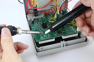
For rework, use controlled heating and suitable tools, and wait until the solder is fully molten before moving the component. Clean and inspect the pads, install the approved replacement with the correct polarity, and verify the relevant circuit function after soldering.
How Do PCB Layout and Assembly Affect SMD Capacitor Reliability?
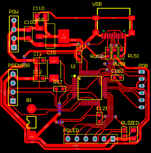
The PCB footprint should follow the selected component and the intended assembly process. Unequal pad geometry or unbalanced heat flow can promote uneven wetting and tombstoning in small chip components. Paste volume, placement accuracy, and the reflow profile need to work together.
For decoupling, keep the current loop between the capacitor, IC supply, and return path short. Locate vias deliberately and account for their inductance. A larger capacitance value does not automatically compensate for a poor high-frequency connection.
Ceramic capacitors are also vulnerable to mechanical strain. Board bending during depaneling, connector insertion, screw tightening, or handling can crack an MLCC. Review placement near board edges, mounting holes, and other stress locations. Where appropriate, consider flexible terminations and layout guidance from the manufacturer.
Reflow limits belong to the exact component series. Match the assembly profile to component specifications and the solder-paste process, including peak temperature, time above liquidus, and heating and cooling behavior. Repeated rework adds thermal exposure and should be controlled.
AOI can check presence, position, polarity markings where visible, and accessible solder features. It cannot prove that a ceramic body has no hidden internal crack. Combine visual inspection with electrical or functional tests that address the circuit’s actual failure risks.
FAQs About SMD Capacitors
Can an SMD capacitor make an audible noise?
Some ceramic capacitors can vibrate under changing electrical stress and couple that vibration into the PCB, producing audible sound.
Can SMD capacitors be connected in parallel?
Their capacitances approximately add at low frequency, but effective capacitance, ESR, inductance and layout determine the combined behavior in operation.
Does an empty capacitor footprint mean a component is missing?
It may be an intentional do-not-populate position, so check the BOM and assembly variant before installing a part.
Does C104 printed on a PCB mean a 100 nF capacitor?
C104 is normally a reference designator identifying a circuit position, not a three-digit capacitance marking.
Does a capacitor’s voltage rating indicate the voltage it generates?
No, the rating describes an operating limit under specified conditions; the circuit determines the voltage across the capacitor.
Can AOI detect every cracked ceramic capacitor?
No, internal cracks can remain invisible to optical inspection and may require electrical testing or further analysis.
Do two capacitors in series automatically double the voltage rating?
No, voltage sharing depends on capacitance, leakage and circuit conditions, so a series arrangement needs a specific design review.
How Can EBest Circuit Support Your Capacitor Assembly Project?
At EBest Circuit, we support PCB fabrication, component sourcing, and SMT assembly with inspection and testing matched to the project. For capacitor-heavy designs, our manufacturing review can address footprint consistency, polarity, placement access, soldering requirements, and handling around mechanically sensitive components.
Send your Gerber files, BOM with manufacturer part numbers, assembly drawings, quantities, and test requirements to sales@bestpcbs.com. Include approved alternatives and any critical capacitance, ESR, temperature, or qualification requirements so we can review the build and prepare an appropriate quotation.