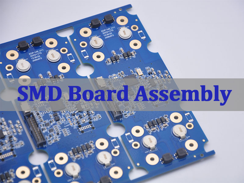
A lead-free PCB assembly order can still fail even when every supplier agrees to use lead-free solder. A mismatched surface finish, an unapproved BOM substitution, a moisture-sensitive component or an incomplete inspection requirement can stop production after materials have already been purchased.
You can reduce that risk before quotation. Give your PCB/PCBA supplier one controlled set of fabrication files, BOM data, assembly requirements and acceptance criteria. The result is a quote you can compare, a process the factory can repeat and clearer evidence for accepting the finished boards.
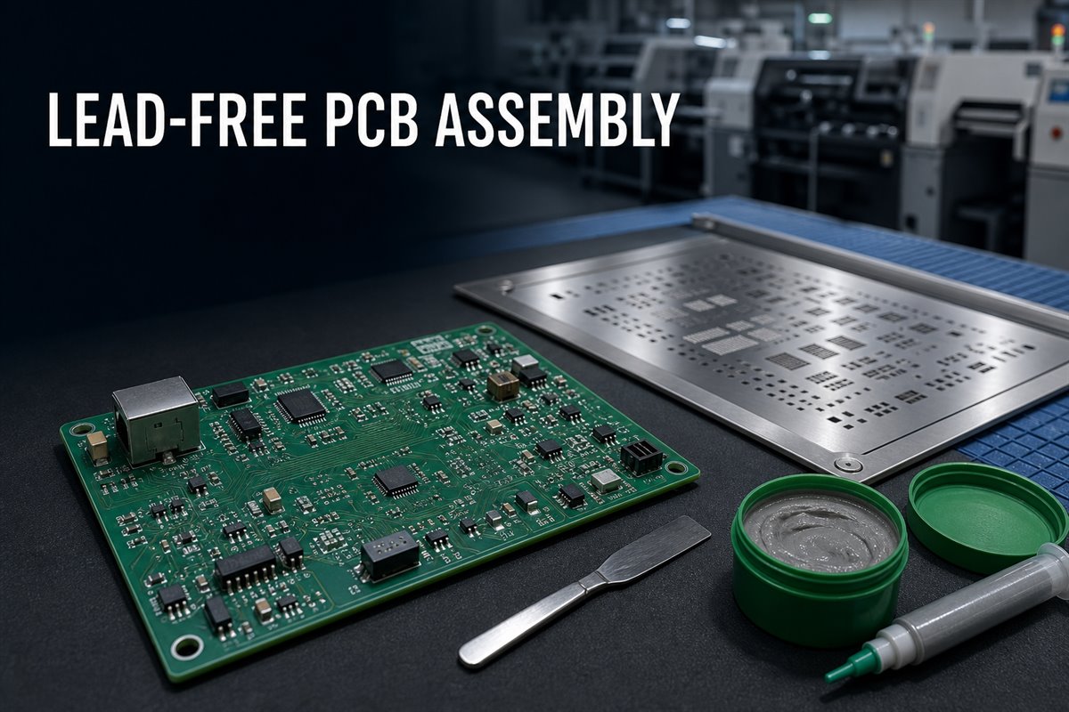
What Changes When You Request Lead-Free PCB Assembly?
The main change is not simply the removal of lead. Lead-free production affects the PCB finish, solder alloy, component compatibility, thermal exposure, storage controls, inspection plan and documentation that must work together.
- Avoid a false sense of compliance. “Lead-free” describes a material or process requirement. It does not, by itself, prove that a finished product meets every applicable RoHS requirement. RoHS restricts several substances, includes scope rules and exemptions, and places product-level responsibilities on the organization putting the equipment on the market. Define the exact declaration or supporting records you need instead of asking only for “RoHS assembly.”
- Make the requirement visible throughout the order. State the lead-free requirement in the RFQ, BOM notes, assembly drawing and purchase order. Identify any approved alloy, PCB finish, component termination or marking requirement. This reduces the chance that fabrication, sourcing and assembly teams work from different assumptions.
The customer remains responsible for released design requirements, product-level compliance decisions and applicable legal obligations. The PCB/PCBA manufacturer can then review manufacturability, source against the approved BOM and build to the agreed assembly and inspection plan.
What Must Be Confirmed to Avoid Requotes and Schedule Changes?
A short RFQ can produce a fast price, but missing requirements often return later as engineering questions, material changes or added cost. Confirm the decisions that affect purchasing and production before comparing quotations.
- Define the production scope. State whether the order covers bare PCB fabrication, component sourcing, SMT, through-hole assembly, programming, functional test assistance, coating, cleaning, packaging or another agreed operation. A quote for SMT placement alone cannot be compared with a turnkey PCBA quote.
- State what is fixed and what may change. Mark customer-controlled items such as approved manufacturers, do-not-substitute parts, PCB finish, solder alloy and acceptance class. If alternatives are allowed, define who can approve them. This gives purchasing a usable path when the original part is unavailable without allowing silent substitutions.
- Identify the evidence required at shipment. If you need certificates of conformity, material declarations, lot traceability, inspection reports, X-ray records or test results, include them in the RFQ. Records requested after production may not exist in the form your quality team expects.
A complete quotation should show major assumptions, exclusions and customer confirmations. That lets you compare risk and total scope—not only unit price.
How Can You Prevent PCB, BOM and Component Mismatches?
The safest lead-free process begins with one released data package. When the PCB revision, BOM revision and placement data do not match, the assembly may be technically buildable but still be the wrong product.
- Use exact component identities. Each BOM line should include the manufacturer, manufacturer part number, quantity, reference designators and an approved-alternative rule. Descriptions such as “10 µF capacitor” are not enough to confirm package, voltage rating, dielectric, tolerance or lead-free termination.
- Match footprints before purchasing. Check the land pattern, package dimensions, pin-one orientation, polarity and component height against the assembly data. A sourcing substitute may be electrically similar but mechanically incompatible with the released PCB.
- Keep revisions synchronized. Gerber or ODB++ data, drill files, fabrication drawing, BOM, centroid/XY file, assembly drawing and test instructions should carry the same released revision. Remove obsolete files from the RFQ package so the factory does not have to guess which version controls the order.
- Resolve availability before it becomes a line stop. An early PCB assembly manufacturer RFQ review can identify obsolete parts, long lead times, minimum order quantities and uncertain lead-free status. The supplier can propose sourcing options, but the customer should approve changes that affect form, fit, function, compliance or reliability.
How Can You Avoid a Surface Finish and Solder Alloy Mismatch?
The lowest-risk choice is the combination already approved for your product—not a universal “best” finish or alloy. Confirming that combination before PCB fabrication prevents bare boards from arriving with a finish that conflicts with the assembly plan.
- Specify the PCB finish clearly. ENIG, immersion silver, immersion tin, OSP and lead-free HASL have different handling, storage, planarity and process considerations. The correct choice depends on the released design, component mix, shelf-life needs and customer requirements.
- Name the solder material when it matters. If the product requires a particular lead-free solder alloy or solder-paste specification, state it in the assembly documentation. Do not assume every supplier uses the same alloy for reflow, wave soldering, selective soldering and hand operations.
- Control mixed-finish and mixed-alloy risks. Component terminations, PCB finish, solder paste and any secondary soldering operation should be reviewed as one assembly system. If a legacy or exempt lead-bearing component is involved, identify it before quotation and agree on handling, labeling and process requirements.
This confirmation protects more than solderability. It also prevents a late material change from invalidating an approved process, test plan or customer record.
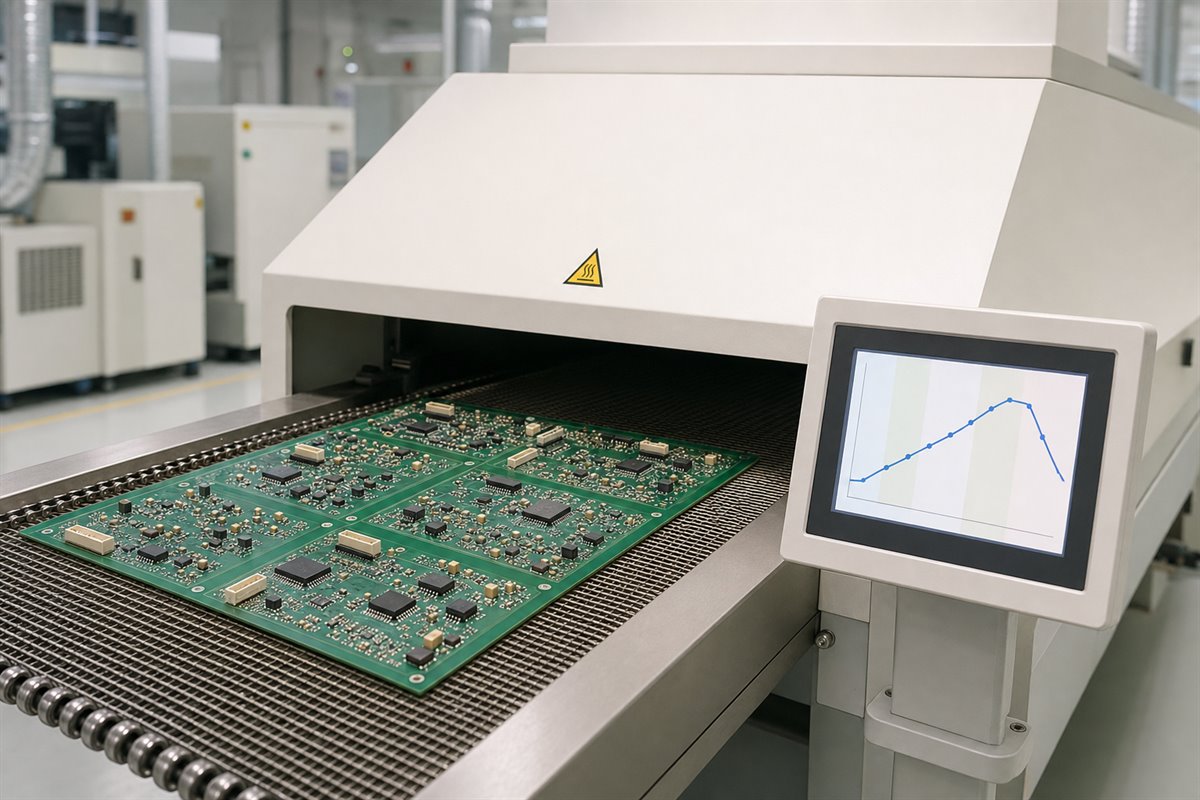
How Can You Protect Boards and Components During Lead-Free Reflow?
Lead-free assembly often uses a different thermal process from conventional tin-lead production. The useful question is not “What temperature does the factory use?” It is “Can this specific PCB and component set pass through the agreed process without damage or inadequate solder joints?”
- Build the profile around real constraints. Component temperature ratings, solder-paste guidance, board thickness, copper distribution, thermal mass and oven capability all influence the usable process window. A single peak-temperature promise does not describe the complete heating and cooling cycle.
- Review heat-sensitive items early. Large packages, fine-pitch devices, bottom-terminated components, plastic connectors, LEDs, switches, batteries and other sensitive parts may require special attention. Identify parts with limited reflow exposure or separate assembly instructions before materials are released.
- Reduce board-level thermal risk. Thin boards, heavy-copper areas, uneven copper distribution and large thermal-mass differences can make uniform heating more difficult. PCB manufacturability review and assembly review can flag concerns, but the customer retains responsibility for product design and reliability targets.
When the process window is narrow, an agreed profiling plan gives both sides a better production reference than a generic oven setting.
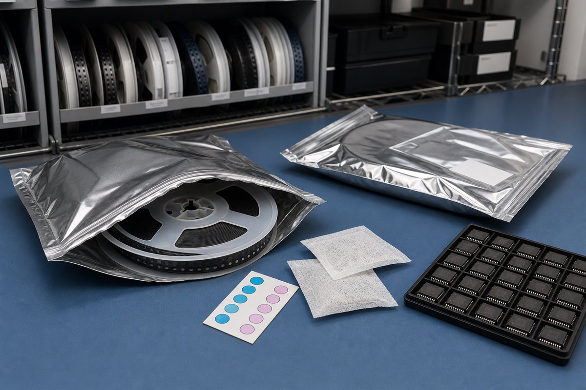
How Can You Prevent Moisture Damage Before Reflow?
Moisture controls protect components from internal damage and help avoid schedule disruption caused by uncertain storage history. The risk is highest when moisture-sensitive devices remain open beyond their allowed exposure or arrive without clear packaging records.
- Provide or retain moisture-sensitivity information. The BOM and component documentation should make sensitive devices identifiable. Packaging labels, moisture barrier bags, desiccant, humidity indicators and opening records help production determine whether a part remains ready for assembly.
- Do not improvise baking conditions. Baking can restore process readiness in some situations, but the permitted temperature and duration depend on the component, packaging and applicable instructions. Excessive or unsuitable baking can damage parts, trays, tape or solderability. Use component-manufacturer and agreed process guidance rather than a universal rule.
- Plan for split lots and partial use. If a reel will return to storage, define resealing and tracking expectations. This prevents the next build from inheriting an unknown floor-life history.
These controls reduce the chance of popcorning, delamination, latent damage and avoidable production holds without pretending that visual inspection alone can prove internal condition.
Which Process Controls Reduce Rework and Solder Defects?
Rework becomes less likely when the process is controlled at the points where variation enters—not only inspected after assembly.
- Solder-paste control: Confirm the approved paste, storage condition, thawing/handling method and usable life.
- Printing control: Match stencil design and printing parameters to pad geometry and component needs; monitor paste deposition when the assembly requires it.
- Placement control: Verify package data, polarity, orientation and feeder setup before the full lot runs.
- Reflow control: Use a profile based on the assembly and record the agreed production parameters.
- Secondary soldering control: Define alloy and flux for wave, selective or hand soldering so later operations do not introduce an uncontrolled material.
- Cleaning control: State cleanliness or no-clean requirements, especially when residues could affect coating, high-impedance circuits or customer acceptance.
- Rework control: Agree on authorized repair methods, acceptance criteria and traceability before repeated heating changes the assembly.
IPC J-STD-001 addresses soldered assembly process and material requirements, while IPC-A-610 addresses post-assembly acceptability. If your order invokes a standard, specify the required revision, class and any customer-specific criteria. A standard number without those details can still leave two parties using different acceptance rules.
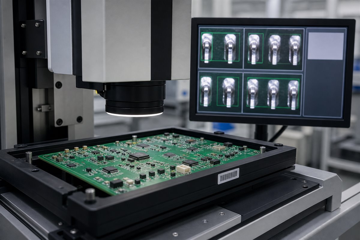
What Inspection and Test Records Help You Accept the Assembly?
Ask for evidence that supports your acceptance decision. More records are not automatically better; the right records connect the agreed requirement to the delivered lot.
- Use inspection where it can reveal the defect. Automated optical inspection can check visible placement and solder conditions. X-ray inspection can provide evidence for hidden joints such as BGAs or bottom-terminated components when included in the inspection plan. Neither method replaces electrical or functional testing.
- Separate workmanship checks from product verification. Visual or X-ray acceptance addresses assembly conditions. In-circuit test, flying-probe test, programming and functional test answer different questions and require suitable fixtures, software, limits or customer instructions. Define what is included before quotation.
- Request traceable, usable outputs. Depending on the project, useful records may include:
- certificate of conformity;
- PCB and component lot references;
- first-article inspection results;
- AOI or X-ray records for agreed locations;
- electrical or functional test results;
- approved deviation or substitution records;
- assembly revision and quantity accepted.
The acceptance plan should state who reviews failures, what constitutes a pass and how nonconforming assemblies are handled. This prevents a folder of test files from becoming a substitute for an agreed decision process.
What Files Help You Get an Accurate Quote the First Time?
Send files that let fabrication, purchasing and assembly quote the same product. The following package gives the supplier a practical starting point:
- Gerber or ODB++ fabrication data and NC drill files;
- PCB fabrication drawing, stack-up and controlled-impedance requirements where applicable;
- BOM with exact manufacturer part numbers, approved alternatives and do-not-substitute items;
- centroid/XY placement data;
- assembly drawings showing polarity, orientation and special instructions;
- lead-free requirement, approved surface finish and solder alloy information;
- applicable workmanship standard, revision, class and customer criteria;
- test method, test limits, fixtures, firmware and programming files where included;
- required compliance, inspection, traceability and shipment records;
- target quantity, panel or delivery needs and approved revision.
Before sending the RFQ, remove superseded files and identify anything still awaiting approval. An open issue is manageable when it is visible. A hidden assumption usually appears later as a requote, an engineering hold or rework.
EBest Circuit (Best Technology) can review the released PCB data for manufacturability, support PCB fabrication, source against the approved BOM, assemble SMT and through-hole components, and coordinate agreed inspection and testing assistance. Send the complete package to sales@bestpcbs.com for review and quotation.
FAQs About Lead-Free PCB Assembly
Does lead-free PCB assembly automatically make a product RoHS compliant?
No. Lead-free soldering addresses only part of the material picture. Product scope, restricted substances, exemptions, components, documentation and market responsibilities must also be evaluated by the responsible organization.
Which lead-free solder alloy should I specify?
Use the alloy approved for your product and process. Consider component terminations, PCB finish, reliability requirements and any secondary soldering operations. The assembly supplier should not change a specified alloy without approval.
Can the same PCB be used for leaded and lead-free assembly?
Sometimes, but it should not be assumed. Review the PCB finish, component compatibility, land patterns, thermal exposure, labeling and product requirements before using one design in both processes.
What causes the most avoidable delays in a lead-free PCBA order?
Common causes include mismatched file revisions, incomplete BOM data, unapproved substitutions, unclear finish or alloy requirements, unavailable components, missing test inputs and documentation requested only after production.
What should I send first for a lead-free PCB assembly quote?
Send the released PCB fabrication files, fabrication drawing, BOM/AVL, centroid data, assembly drawings, lead-free and finish requirements, quantity, acceptance criteria, test inputs and required shipment records. A complete package supports a clearer circuit board assembly process and reduces assumptions and makes competing quotations easier to compare.
Ready to review a lead-free PCB assembly project? Send your released files and requirements to sales@bestpcbs.com. EBest Circuit will identify manufacturability, sourcing and assembly questions before they become purchasing or production delays.