PCB manufacturing PCB manufacturing
Home > Blog

QR code on PCB

How to Add a QR Code on PCB: Laser Marking, Size, and Traceability
Wednesday, July 22nd, 2026

A QR code on PCB links a circuit board to production, test, repair, or warranty records. It may open a technical document or provide a unique serial number for each unit.

The finished mark must remain readable after fabrication, reflow, cleaning, coating, and assembly. Its size, contrast, placement, and marking method all matter.

Static codes often suit PCB silkscreen. Unit-level serial numbers normally require laser marking, inkjet coding, or variable-data labels. Data Matrix may be better when board space is limited.
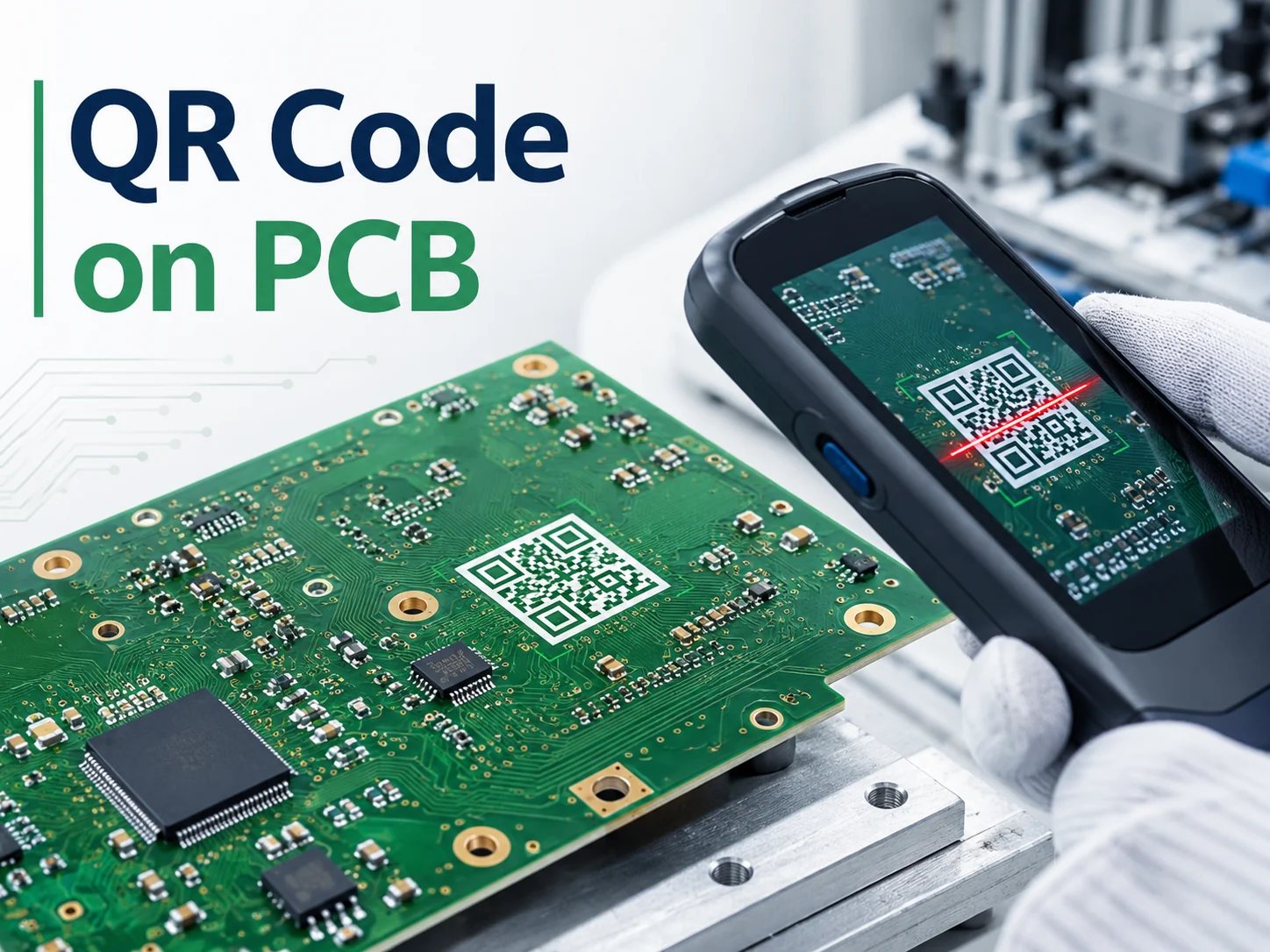
QR code on PCB being scanned during circuit board inspection

What Is a QR Code on PCB?

A QR code on PCB is a machine-readable 2D symbol placed on a bare circuit board, assembled PCBA, production panel, or label. It can contain text, URLs, serial numbers, or a reference to an external database.

PCB QR codes generally fall into 2 categories:

  • Static QR code: The same information appears on every board, such as a product number, website, manual, or assembly document.
  • Serialized QR code: Each board receives a unique code linked to its production lot, test record, firmware version, repair history, or warranty information.

A static code can be included in the Gerber silkscreen layer. A serialized code changes from board to board, so it needs a variable-data process such as laser marking, inkjet printing, or automated label application.

A PCB-level code identifies the board, panel, or assembled product, while codes on IC packages identify individual components.
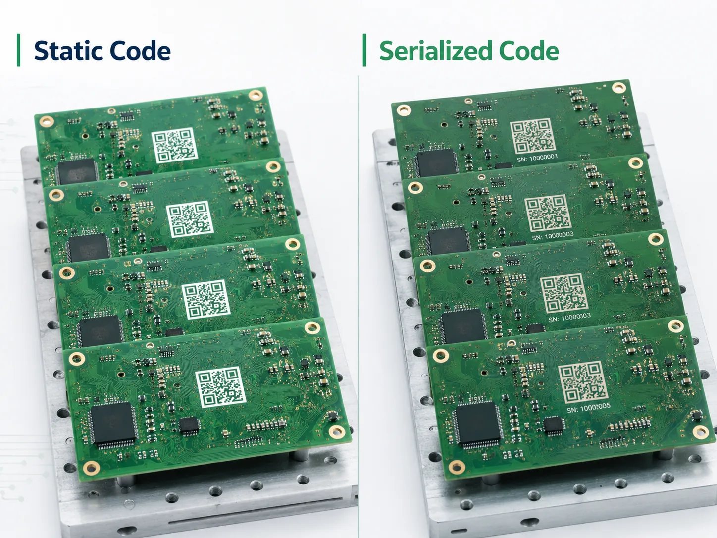
Comparison of static and serialized QR codes on printed circuit boards

Why Are QR Codes Used on Circuit Boards?

QR codes improve identification and traceability while reducing manual data entry.

Typical applications include:

  • PCB part number and revision identification
  • Production lot and manufacturing date tracking
  • Panel and unit position recording
  • AOI, X-ray, ICT, and functional test linking
  • Firmware programming records
  • Repair and warranty history
  • Access to drawings, manuals, and service instructions
  • Anti-counterfeit verification

A bare PCB code may identify the fabrication lot, material batch, and revision. A PCBA code can also link component lots, SMT inspection results and functional tests, and firmware.

In high-volume production, each workstation can scan the code and update the same MES record. If an issue appears later, affected boards can be isolated quickly.

The code should therefore match the record structure used by the factory. A serial number that cannot be connected to material, process, and test data provides identification, but not complete traceability. Before production, confirm which fields will be stored, who can update them, and how long the records must remain available.

What Information Can a PCB QR Code Store?

A QR code can hold substantial data, but more characters create a denser symbol. Dense codes need smaller modules or more board area, both of which reduce manufacturing tolerance.

For PCB applications, it is usually better to encode a short identifier such as:

  • Part number
  • PCB revision
  • Serial number
  • Manufacturing lot
  • Production date
  • Panel and unit position
  • Test record ID
  • Firmware reference
  • Short database URL

For example, PCB-260722-P18-U04 could identify a production date, panel, and unit position. Detailed material, inspection, test, firmware, and repair data can remain in a linked database.

Sensitive data should not be written directly into an open QR code. Use the code as a record key and protect the linked system with access control.

How Can You Add a QR Code to a PCB?

Select the marking method according to data variability, code size, durability, board material, and production stage.

Marking method Best suited for Main advantages Main limitations
PCB silkscreen Static codes Low additional cost and included in standard PCB artwork Limited resolution and no unit-level variation
Laser marking Unique serial numbers Permanent, precise, and easy to automate Additional process cost and parameter setup
High-temperature label Variable data and readable text Strong contrast and flexible format Label and adhesive must survive assembly
Copper or solder mask pattern Large static codes Integrated into the PCB structure Uses more board area and may have weak contrast
Inkjet marking Automated variable coding Fast and contactless Ink durability must be validated
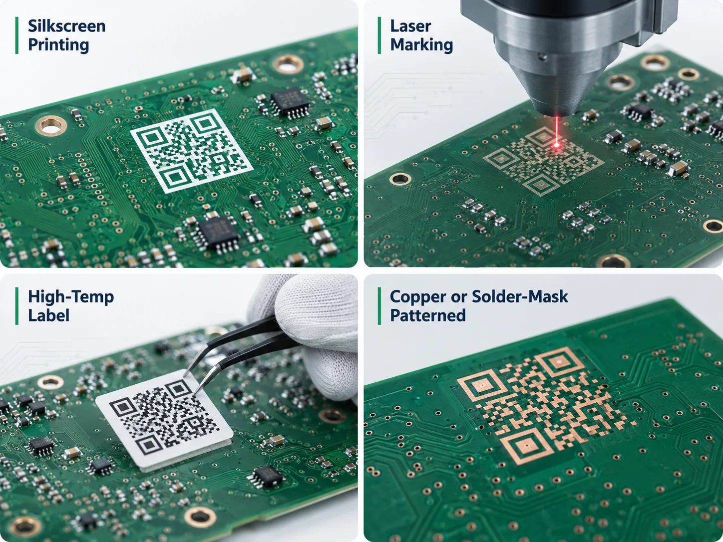
Silkscreen laser label and copper methods for adding a QR code to a PCB

PCB Silkscreen

Silkscreen suits projects where the same code appears on every PCB. The symbol is added to the legend layer and printed during standard fabrication.

Use vector artwork or generate the code directly in PCB design software. Screenshots and compressed bitmaps may produce uneven modules after Gerber conversion. Fine ink areas can also spread, merge, or become incomplete.

Laser Marking

Laser marking is usually preferred for unit-level serialization. The software generates a different code for each PCB without changing the Gerber files.

It can support automatic numbering, camera alignment, scan verification, duplicate detection, and database registration. Laser parameters must match the solder mask and laminate. Excessive energy may expose copper, while insufficient energy produces weak contrast.

High-Temperature Labels

Labels can carry both a QR code and human-readable text. They are useful when information changes late in production or strong contrast is required.

The material and adhesive must survive:

  • Lead-free reflow
  • Flux and cleaning chemicals
  • Conformal coating
  • Operating temperature and humidity

General-purpose labels are not suitable for electronics assembly.

Copper or Solder Mask Patterns

A static code can also be formed with exposed copper or solder mask openings. This creates a permanent mark without ink, but it uses more board space.

Fine copper islands and narrow solder mask webs may exceed standard fabrication capability, so this method needs DFM review.

How Does Laser QR Code Marking Work on PCB?

A laser QR code on PCB creates a permanent code on the PCB surface after solder mask processing. It is suitable for variable data because every board can receive a unique serial number.

A typical process includes:

  1. Define the serial-number format and starting value.
  2. Position the PCB or panel using fixtures or camera alignment.
  3. Set laser power, speed, focus, and pulse parameters.
  4. Generate and mark the QR code.
  5. Scan and verify the finished code.
  6. Save the result to the production database.
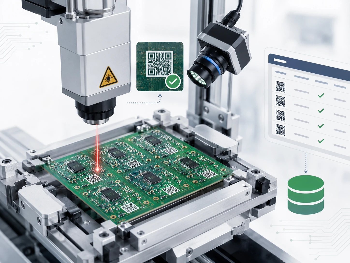
Automated laser QR code marking and machine vision verification on a PCB panel

The laser creates contrast by removing or changing a thin surface layer without damaging the PCB structure.

The marking stage should be defined in advance. Marking before assembly provides clear surface access, but the code may later be covered by components, heat sinks, shields, connectors, or an enclosure. Marking after assembly avoids some of these risks but requires a safe area away from sensitive parts.

For quotation, specify whether the code is required on the production panel, each bare PCB, each assembled PCBA, or the final enclosure. Panel-level marking supports process tracking, but it disappears when the rail is removed.

What Size Should a QR Code on PCB Be?

There is no universal minimum size. The correct dimensions depend on:

  • Encoded data length
  • QR version
  • Error-correction level
  • Module size
  • Marking process
  • Surface contrast
  • Scanner type
  • Reading distance

A QR code is built from square modules:

Code width = total modules × module size

A Version 1 QR code contains a 21 × 21 module data area. After adding a 4-module quiet zone on each side, the total area becomes 29 × 29 modules.

With a 0.30 mm module:

29 × 0.30 mm = 8.70 mm

This is a geometric size, not a guaranteed manufacturing limit. Silkscreen ink spread, solder mask texture, reflection, and registration tolerance may require a larger code.

Do not approve the design from a screen image alone. A useful prototype check should include several finished boards, the planned scanner, normal production lighting, and the expected reading distance. The code should also be tested after any cleaning, coating, or assembly step that could change contrast or block access.

To improve scan reliability:

  • Keep the encoded string short.
  • Use the largest practical module size.
  • Preserve the complete quiet zone.
  • Avoid uneven scaling.
  • Use vector artwork.
  • Test with the intended scanner.
  • Approve a fabricated sample.

Laser marking can normally support smaller modules than silkscreen. When board space is limited, shorten the identifier or consider Data Matrix. Scanner capability should be confirmed early because an industrial camera may read a smaller code than a smartphone.

Where Should You Place a QR Code on a PCB?

Place the code in a flat, open area that remains visible when scanned.

A suitable location should:

  • Stay clear of pads, vias, test points, and exposed copper
  • Include enough space for the full quiet zone
  • Remain away from routed edges, V-scores, slots, and mounting holes
  • Avoid components, shields, connectors, heat sinks, and cables
  • Remain visible after enclosure assembly
  • Use a consistent orientation for automated scanning
  • Avoid highly reflective surfaces
  • Remain readable after coating and cleaning
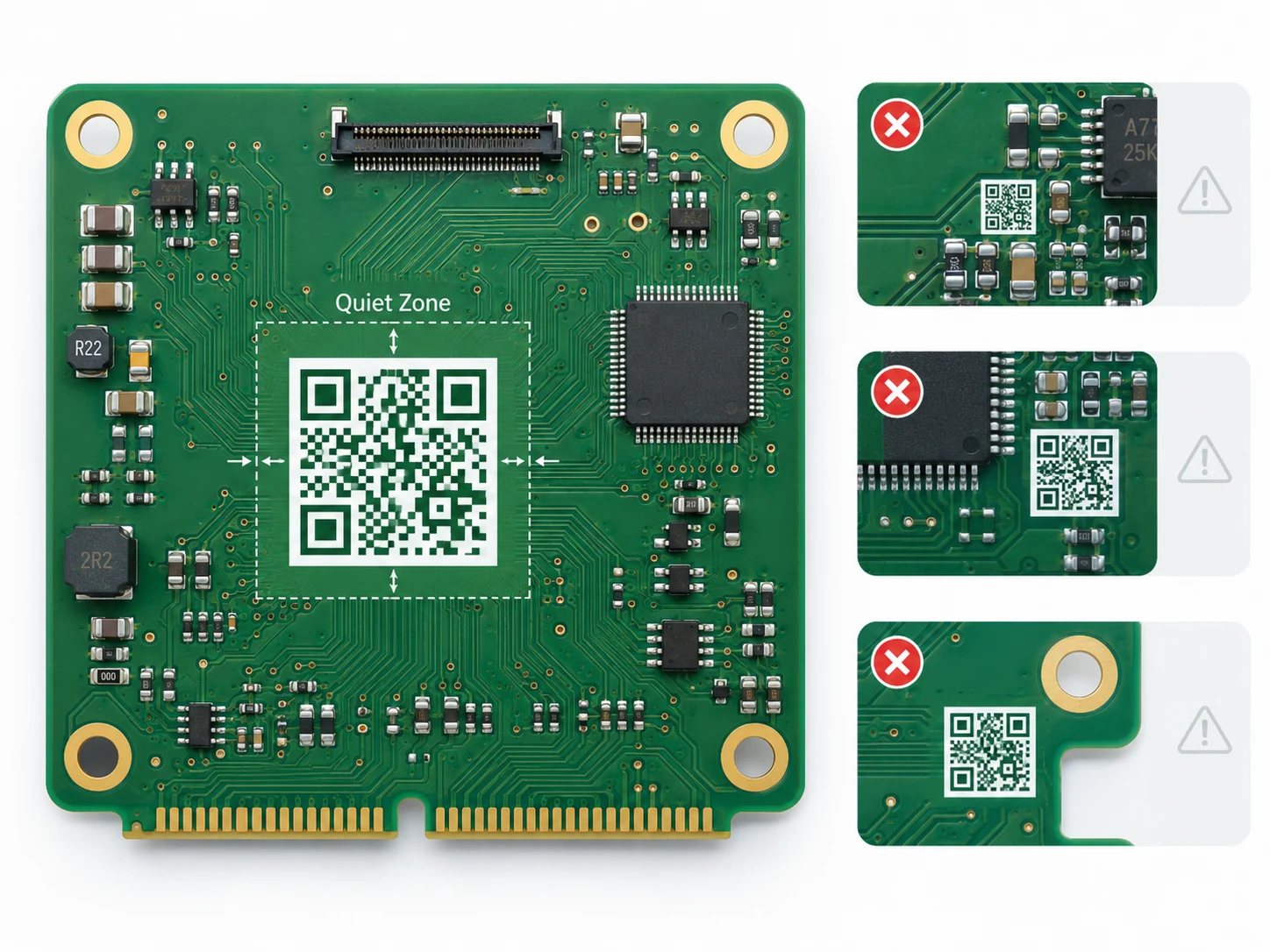
Correct PCB QR code placement with quiet zone and examples of poor placement

The top side is often easier to scan; the bottom may offer more space but become inaccessible after installation.

A code on the panel rail can track fabrication and SMT, but it disappears after depanelization. Permanent traceability therefore requires a code on each PCB.

Placement should be reviewed before layout release. Late additions often cause insufficient quiet zone, fixture interference, component coverage, or poor scanner access.

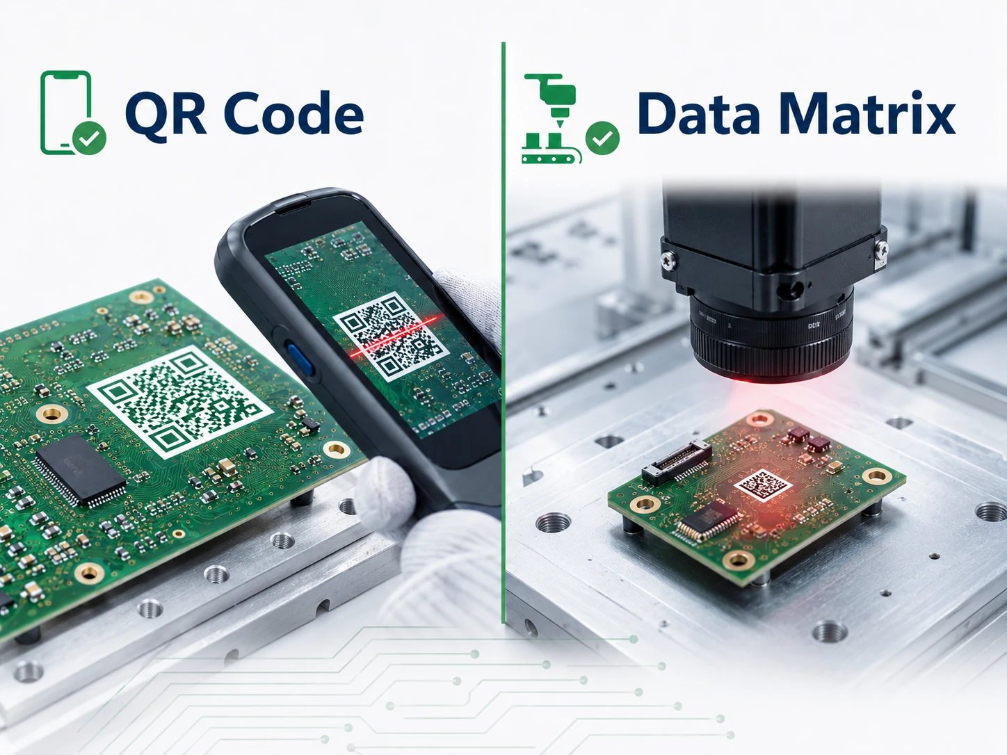
QR Code vs Data Matrix: Which Is Better for PCB Traceability?

The main decision is whether smartphone readability or compact size matters more.

Selection factor QR Code Data Matrix
Data density Good Higher for compact industrial data
Smartphone compatibility Widely supported Less consistent
Industrial scanner support Excellent Excellent
Required PCB area Usually larger Usually smaller
Typical use Manuals, warranty, websites, field service Factory serialization and MES tracking
Suitability for small PCBs Moderate Strong
Human recognition High Lower
Laser marking Suitable Very suitable
QR Code and Data Matrix comparison for PCB traceability

Use QR Code for smartphone access and Data Matrix when space is limited and industrial cameras handle the reading. Confirm scanner compatibility before finalizing the symbol.

Why Does a QR Code on PCB Fail to Scan?

Most failures come from the physical marking process rather than the QR logic.

Modules Are Too Small

Fine silkscreen modules may merge, spread, or disappear.

Fix: Increase module size, shorten the encoded value, or use laser marking.

The Quiet Zone Is Blocked

Nearby text, copper, vias, solder mask openings, or board edges can interfere with detection.

Fix: Treat the quiet zone as a layout keep-out area.

Contrast Is Too Low

Glossy solder mask, reflective metal, or weak laser marks reduce readability.

Fix: Evaluate the finished board under real lighting.

The Artwork Was Distorted

Uneven resizing or bitmap conversion changes module proportions.

Fix: Keep a 1:1 aspect ratio and use vector artwork.

Too Much Data Is Encoded

Long URLs and detailed text create dense codes.

Fix: Encode a short ID or database reference.

Reflection or Contamination Interferes

ENIG, coating, flux residue, or dust can blur the code.

Fix: Adjust placement or lighting and verify the code after the final surface process.

Components Cover the Code

A code may scan on the bare PCB but become inaccessible after assembly.

Fix: Review the final 3D assembly and enclosure.

A PCB QR code scanner should be validated for the planned lighting and reading distance. For mass production, define the scanner model, scan distance, lighting, inspection stage, and whether verification is sampled or performed on every unit.

How Should You Specify PCB QR Code Requirements to a Manufacturer?

Clear specifications allow the manufacturer to select the right process and quote accurately.

Provide:

  • QR Code or Data Matrix
  • Static or variable data
  • Bare PCB or assembled PCBA
  • Silkscreen, laser, inkjet, or label
  • Encoded content and data format
  • Serial-number sequence and starting value
  • Code dimensions
  • Marking side and coordinates
  • Required orientation
  • Solder mask color
  • Panel-level or unit-level marking
  • Human-readable text
  • Scanner type
  • Verification requirement
  • Reflow, cleaning, coating, and temperature conditions
  • MES or database integration requirements

A practical specification may look like this:

  • Format: BT26-XXXXXX
  • Starting number: BT26-000001
  • Quantity: 2,000
  • Process: laser marking
  • Code size: 8 × 8 mm
  • Location: bottom side
  • Human-readable text: serial number below the code
  • Inspection: scan every unit after marking

For prototypes, scan marked samples after assembly, cleaning, and coating.

EBest Circuit can review code location, contrast, serialization, panel arrangement, and marking method during DFM and quotation. Submit the QR specification with Gerber files, BOM, assembly drawings, and test requirements.

FAQ

1. What is the minimum size for a QR code on PCB?

There is no fixed minimum size. It depends on the marking method, module size, data length, surface contrast, and scanner. A fabricated sample should be tested before mass production.

2. Is laser marking better than silkscreen for PCB QR codes?

Laser marking is better for unique serial numbers, smaller symbols, and permanent traceability. Silkscreen is more economical for larger static codes.

3. Can a QR code survive PCB reflow soldering and cleaning?

Silkscreen and properly controlled laser marks normally survive standard assembly. Labels must be rated for reflow, flux, cleaning chemicals, and operating temperature.

4. Can every PCB have a unique QR code?

Yes. Laser marking, inkjet printing, and variable-data labels can generate a different code for each board.

5. Can a smartphone scan a QR code on a circuit board?

Yes. A QR code on circuit board surfaces can be scanned when the code has sufficient size, contrast, quiet zone, and visibility. Very small industrial codes may require a dedicated scanner.

6. Should I use QR Code or Data Matrix on a small PCB?

Data Matrix is usually more space-efficient. QR Code is preferable when smartphone compatibility is important.

7. What file format should be used for a PCB QR code?

Use vector artwork or generate the code directly in PCB design software. Avoid screenshots and compressed images.

8. Why does a QR code scan on screen but fail on the finished PCB?

Common causes include small modules, silkscreen ink spread, low contrast, reflection, blocked quiet zones, coating, or distorted artwork.

Need QR Code Support for Your PCB Project?

Before requesting a quotation, define the code format, size, marking stage, serial-number rule, scanner, and verification method. EBest Circuit can review QR code placement, laser marking, panel serialization, and PCBA traceability requirements during DFM.

Send your Gerber files and project requirements to sales@bestpcbs.com.
You may also like

What is a QR code PCB? PCB QR code size
Friday, May 8th, 2026

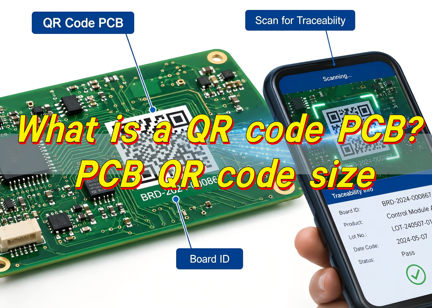
What exactly is a QR code PCB?

A QR code PCB is a printed circuit board that carries a readable QR code directly on its surface. The code can be placed on the silkscreen layer, solder mask opening area, copper-free marking zone, label area, or laser-marked region, depending on the product’s traceability needs and manufacturing method. In practical production, this small square code can connect a circuit board to its batch data, production records, test results, BOM version, inspection history, firmware version, warranty information, or customer-specific tracking system.

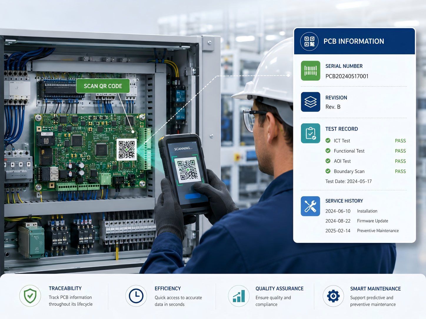
For electronics manufacturers, a QR code on PCB is much more than a visual mark. It acts like a digital identity for the board. When a technician scans it, the system can retrieve useful information within seconds. This is very helpful for PCBA assembly, incoming inspection, quality control, repair, field service, and after-sales analysis.

A PCB QR code can store direct text, a serial number, a URL, a production lot number, or a database reference. In most professional manufacturing systems, the code itself does not need to carry all information. It may only contain a unique ID, while the full data is stored in a factory MES, ERP, quality database, or customer traceability platform. This approach keeps the code compact and easier to scan.

In the PCB industry, QR marking is widely used for industrial electronics, medical electronics, automotive control boards, communication modules, power control boards, smart devices, and OEM assemblies. At EBest Circuit (Best Technology), QR code marking is often treated as part of a broader traceability strategy rather than a simple printing request. The value comes from connecting the physical board to reliable production data, inspection records, and engineering control points.

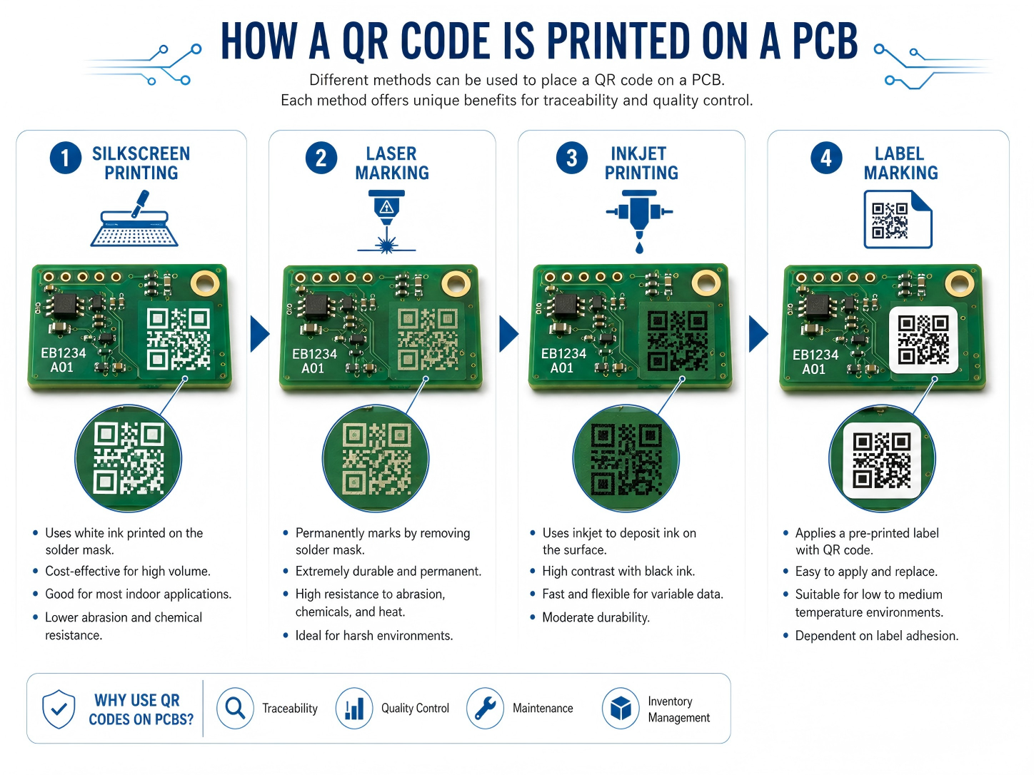
How is a QR code printed onto a PCB?

A QR code can be applied to a PCB in several ways. The most common methods are silkscreen printing, laser marking, inkjet printing, and label-based marking. Each method has its own strengths. The best option depends on the board material, surface finish, code size, production volume, cost target, operating environment, and scanning distance.

Silkscreen is a familiar choice because most PCBs already include a legend layer. The QR code on PCB can be printed with white, black, or yellow legend ink, depending on the solder mask color and contrast requirement. For standard FR4 boards with enough available surface area, silkscreen can provide a practical and cost-effective solution. It is suitable for product identification, revision marking, internal batch tracking, and general factory scanning.

Laser QR code on PCB is often selected when higher precision, better durability, or smaller marking size is needed. A laser can mark the solder mask, exposed copper, metal surface, ceramic substrate, or certain special materials with excellent edge definition. It is a strong option for compact boards, high-density assemblies, harsh environments, and products that require long-term identification.

Inkjet printing is also used in some production lines, especially when variable data is needed at higher speed. A PCB QR code printer can generate unique codes for each board or panel. This method can work well when linked with automated handling equipment and traceability software. Adhesive labels are another option, but they are usually used when direct marking is impractical or when additional human-readable information must be included.

Before printing or marking, the code data must be generated, verified, and placed in the PCB design or production file. For custom QR code PCB orders, the manufacturer may ask for the encoded content, preferred size, position, marking color, serial number format, and scanning requirements. For volume production, the code may be dynamically generated during manufacturing.

MethodBrief DescriptionBest Use CaseMain Advantage
Silkscreen printingQR code printed with legend inkStandard PCB identification and batch trackingCost-effective and easy to integrate
Laser markingCode engraved or marked with laser energyCompact boards, durable marking, industrial useHigh precision and strong permanence
Inkjet printingVariable code printed during productionAutomated serialization and high-volume trackingFlexible for changing data
Adhesive labelPrinted label attached to PCB or productBox build, prototypes, or limited board spaceCan include larger text and barcode data

For stable results, EBest Circuit (Best Technology) usually recommends confirming the marking method during DFM review. This helps avoid placement conflicts with pads, test points, tooling holes, conformal coating zones, and assembly fixtures.

What are the main uses of QR code PCB?

The main use of a QR code PCB is traceability. A well-designed code allows engineers, operators, and quality teams to identify a board quickly and connect it with the right production information. In a modern electronics factory, this supports faster decision-making and cleaner documentation.

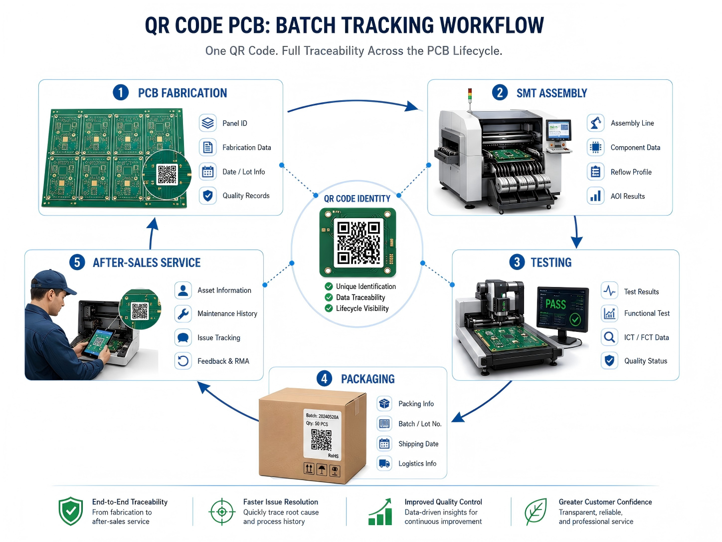
A QR code on circuit board can be used during bare board manufacturing, PCBA assembly, final testing, shipment, repair, and field service. During PCB fabrication, the code may identify the panel number, material batch, surface finish, manufacturing date, and inspection result. During assembly, it may connect to solder paste inspection data, SMT line information, reflow profile, AOI results, X-ray inspection, ICT records, functional test data, and packaging status.

Common uses include:

  • Batch tracking for bare PCBs and assembled boards
  • Serial number control for each finished unit
  • Revision identification for engineering changes
  • Production history lookup during quality review
  • Test data connection for ICT, FCT, AOI, or burn-in
  • Warranty and repair record access
  • Anti-mixing control in high-mix assembly lines
  • Customer-specific product authentication

Another useful application is internal process control. When a board moves from SMT assembly to DIP assembly, coating, testing, packing, or box build, scanning the code can confirm its route and status. This reduces manual recording work and improves accountability across each stage. For projects with many similar board versions, QR scanning brings welcome clarity.

At EBest Circuit (Best Technology), this type of marking can be integrated with turnkey PCB and PCBA production. For customers who need stronger visibility, the QR code can become part of a larger tracking workflow that includes material sourcing, fabrication, assembly, testing, and shipment documentation.

Can QR code silkscreen PCB support batch tracking?

Yes, a QR code silkscreen PCB can support batch tracking when the code is designed, printed, and managed correctly. In many standard projects, silkscreen marking is enough for batch-level traceability. The code can represent a production lot, order number, customer part number, panel number, or revision code. When scanned, it can connect operators to the related manufacturing record.

For batch tracking, the most important point is data structure. The QR code should follow a clear naming and numbering rule. A simple random code may be readable, but it becomes much more useful when it follows a controlled system. For example, a code may include the customer code, product number, PCB revision, batch date, and production sequence. In automated systems, the code may only store a unique ID, while the database stores the full record.

For batch-level tracking, the same code may appear on every PCB within the same batch. For unit-level serialization, each board needs a different code. Silkscreen can support variable data in some production setups, but laser or inkjet marking is usually more efficient for unique serial numbers. That is why the marking method should match the tracking depth.

Tracking TypeDescriptionSuitable Marking MethodTypical Application
Batch trackingOne code represents one production lotSilkscreen, laser, inkjetBare PCB lot control, incoming inspection
Panel trackingOne code identifies a manufacturing panelSilkscreen or laserFabrication and assembly workflow
Unit serializationEach board has a unique codeLaser or inkjet preferredMedical, industrial, automotive, high-value electronics
Process trackingCode updates or links to route statusLaser, inkjet, database-linked codeSMT, testing, repair, final QA

EBest Circuit (Best Technology) can support different traceability levels based on the customer’s product risk, industry requirements, and production volume. For simple projects, batch tracking is often enough. For high-reliability projects, unit-level control gives stronger confidence and better field analysis.

Does QR code marking on PCB affect circuit performance?

QR code marking on PCB is designed to avoid circuit performance issues when it follows correct layout and manufacturing rules. In most cases, the code is placed in a non-electrical area such as the silkscreen layer, solder mask area, board edge, panel rail, or dedicated marking zone. Since the code does not function as part of the circuit, it should be separated from sensitive copper features, pads, impedance-controlled traces, RF sections, high-voltage spacing, and thermal contact surfaces.

For RF, high-speed, high-voltage, or power boards, placement becomes more critical. A QR code should stay away from antenna areas, controlled impedance lines, creepage paths, heat sink contact zones, and exposed copper regions. If laser marking removes or changes solder mask in a sensitive area, the design team should review the effect before release. Good practice is simple: reserve a clean marking area early in layout rather than placing the code at the last moment.

EBest Circuit (Best Technology) usually handles this through engineering review. The QR code location can be checked together with DFM items such as component clearance, fiducial placement, panelization, tooling holes, solder mask clearance, and test point access. This helps keep the board readable, manufacturable, and electrically reliable.

Is custom QR code PCB available for private design?

Yes, custom QR code PCB is available for private design, OEM projects, and customer-specific traceability systems. A manufacturer can place a code according to the customer’s preferred location, size, content, marking method, and brand requirement. The code may be visible on the finished product, hidden inside an enclosure, placed on a panel rail for production use, or located on the assembled board for field service.

Custom marking is especially useful when a company wants to protect its design data, organize product versions, or connect boards with internal management systems. For private design projects, the QR code can link to secure records rather than public web pages. This means only authorized staff can access the detailed information after scanning. The visible code may look simple, while the database behind it contains a rich production history.

Typical custom content may include:

  • Customer part number
  • PCB revision
  • Production date
  • Lot number or serial number
  • Assembly version
  • Internal item code
  • Test record ID
  • Warranty or service reference
  • Secure URL or database lookup code

Custom QR code PCB orders should be discussed before fabrication files are finalized. The customer can define whether the code should appear in Gerber data, be generated during production, or be added by the manufacturer according to a serialization rule. If the code needs to change per board, the manufacturer needs a controlled data file or a system connection. If the same code applies to all boards, it can be integrated into the normal silkscreen artwork.

EBest Circuit (Best Technology) can support customer-specific marking needs across prototype, small batch, and volume production. For OEM customers, this can be combined with PCB fabrication, component sourcing, PCBA assembly, testing, and final packaging to create a smoother production handoff.

What’s the advantage of PCB with QR code?

The main advantage of a PCB with QR code is fast, reliable access to board-level information. Instead of relying only on paper labels, manual notes, or file names, the physical board carries a digital reference that follows it through production and use.

In electronics manufacturing, small errors can create large delays. A wrong revision, mixed batch, missing test record, or unclear repair history can slow down delivery and increase review time. A scannable code gives operators a direct way to confirm the board identity. When connected to a database, it can show the build status, production route, inspection result, or customer order details.

For quality control, QR marking helps create a stronger evidence chain. If a customer reports a field issue, the manufacturer can trace the affected board back to its production batch, material lot, inspection data, and test result. This supports faster root cause analysis and more confident corrective action. For products used in medical, industrial, automotive, aerospace, or communication equipment, this visibility is a clear operational advantage.

AdvantageWhat It Means in PracticeValue for Customer
Faster identificationScan the board instead of manually reading long codesSaves inspection and service time
Better traceabilityConnects the board to production and test recordsImproves quality control
Cleaner version controlConfirms revision and product model quicklyReduces mix-up risk
Efficient repair supportLinks to previous repair or test historySpeeds up troubleshooting
Stronger documentationSupports batch records and audit reviewHelpful for regulated industries
Scalable production controlWorks with MES, ERP, and warehouse systemsSupports growth and repeat orders

A QR code on circuit board also helps communication between supplier and customer. When both sides use the same code reference, discussions become clearer. Instead of describing a board by photo, file name, or partial marking, both teams can refer to the same scan data. This is simple but very powerful during engineering changes and after-sales support.

EBest Circuit (Best Technology) sees QR marking as a practical way to strengthen manufacturing discipline. It does not replace good process control, but it makes that control easier to verify. For customers who value dependable production and transparent communication, this small mark can create a big improvement in workflow confidence.

How durable is QR code printing on circuit boards?

The durability of QR code printing on circuit boards depends on the marking method, board surface, operating environment, cleaning process, coating treatment, and handling conditions. A properly designed and manufactured code can remain readable through assembly, testing, shipment, and long-term use. For products that face heat, moisture, solvents, abrasion, or outdoor exposure, the marking method should be selected with extra care.

Silkscreen QR codes are durable enough for many standard electronics. The legend ink is cured onto the solder mask and can withstand normal assembly processes. It works well for indoor electronics, control boards, consumer devices, power supplies, and many industrial products. However, repeated abrasion, aggressive cleaning agents, or heavy conformal coating can reduce readability. Good placement helps protect the code from wear.

Laser marking is often more durable because it changes the surface rather than sitting only as an ink layer. A laser QR code on PCB can resist cleaning, handling, and long service life more effectively. It is often preferred for compact industrial boards, automotive modules, medical electronics, metal substrates, ceramic PCBs, and products that need permanent identification. The exact durability depends on the substrate and laser process settings.

Inkjet marking can be effective when the right ink and curing method are used. It is useful for fast serialization, especially in automated production. The ink must be compatible with solder mask, cleaning chemistry, and operating temperature. Adhesive labels can provide good readability, but their long-term performance depends on adhesive quality, temperature range, humidity, and available bonding surface.

Marking MethodDurability LevelSuitable EnvironmentNotes
SilkscreenGood for standard useIndoor electronics, general assembliesBest with good contrast and protected location
Laser markingVery strong for permanent IDIndustrial, medical, automotive, harsh-use productsExcellent for small and precise codes
Inkjet printingGood with correct inkAutomated serialized productionNeeds process validation
Label markingVaries by label materialBox build, enclosure, large ID areaAdhesive quality is important

For harsh environments, it is wise to test scanning after cleaning, reflow, coating, thermal cycling, or aging. EBest Circuit (Best Technology) can review the product environment and suggest a suitable approach. This helps the code remain readable when the board reaches real use, not only when it leaves the production line.

Can QR code PCB be used in industrial electronics?

Yes, QR code PCB can be used very effectively in industrial electronics. In fact, industrial products are one of the strongest use cases for board-level identification. Industrial control boards, power modules, automation equipment, sensors, motor drives, communication gateways, test instruments, and monitoring systems often require long service life, stable documentation, and fast maintenance support. A scannable board identity makes these tasks easier.

Industrial electronics are frequently produced in multiple revisions over several years. A control board may look almost the same from the outside while its firmware, component alternatives, connector choices, or circuit revision changes over time. A QR code on PCB helps maintenance teams identify the exact board version before replacement or repair. This is very useful when equipment downtime is costly.

For factories and equipment makers, QR codes also support spare part management. A technician can scan the board and confirm whether the replacement part matches the machine model. The code may connect to installation instructions, calibration records, test data, or service logs. In large facilities, this improves maintenance speed and reduces the chance of using the wrong board.

In industrial electronics, the QR code should be part of the product design plan, not a late decoration. Designers should reserve enough space, define scanner access, check coating coverage, and confirm the code remains visible after assembly. When the board is installed vertically or inside a narrow housing, scanning angle becomes important. A readable code in CAD may be hard to scan in the finished machine if access is limited.

EBest Circuit (Best Technology) supports industrial customers with PCB fabrication, PCBA assembly, testing, and traceability-oriented manufacturing. For control systems, automation equipment, and durable electronics, QR marking can be combined with inspection records and production data to create a more dependable manufacturing record.

What design rules apply to QR code PCB layout?

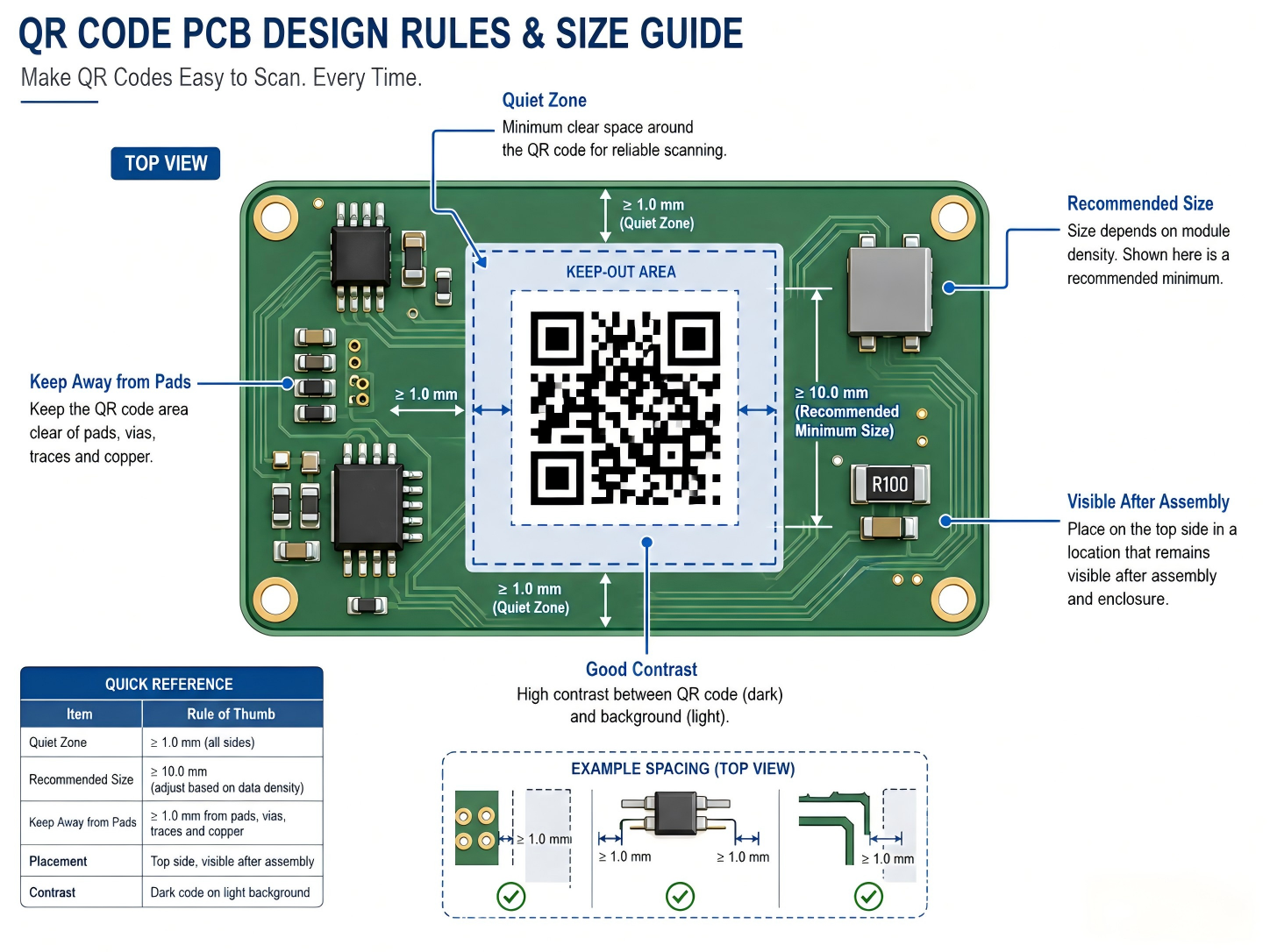
QR code PCB layout should focus on readability, contrast, size, location, clearance, and manufacturing tolerance. A code that looks fine on screen may become difficult to scan after printing if the modules are too small or the surrounding area is crowded. The goal is simple: make the code easy for scanners, operators, and service teams to read under real production conditions.

PCB QR code size is one of the most important design points. The minimum size depends on the amount of encoded data, QR version, error correction level, marking method, scanner quality, and required scanning distance. For many PCB silkscreen applications, a practical size may start around 5 mm × 5 mm for very simple data, but 7 mm × 7 mm to 10 mm × 10 mm is often more comfortable for reliable factory scanning. For laser marking, smaller codes may be possible because the edge definition is sharper. For manual handheld scanning, larger is usually better.

The code should also include a quiet zone. This is the blank margin around the QR pattern. Without enough margin, nearby text, copper, pads, components, or solder mask openings may disturb recognition. A quiet zone of at least four modules is a common QR code principle. On PCB artwork, this means the designer should keep the area around the code clean.

Useful layout rules include:

  • Reserve a clean rectangular marking area early in PCB layout.
  • Keep the code away from component pads, vias, test points, fiducials, and screw holes.
  • Maintain a quiet zone around the QR pattern.
  • Avoid placing the code under tall components, shields, heat sinks, or labels.
  • Select a size that matches the marking method and scanner distance.
  • Use short encoded data when space is limited.
  • Confirm readability after soldering, washing, coating, and final assembly.
  • Keep codes away from RF antenna zones, high-voltage spacing areas, and thermal contact surfaces.

For PCB QR code size planning, the amount of data matters. A short serial number can use fewer modules and stay readable at a smaller size. A long URL or dense information needs more modules, which requires a larger printed area. In many professional systems, using a short unique ID is better than encoding a long data string. The ID can point to a database where full records are stored.

Design FactorPractical RecommendationWhy It Matters
Code sizeUse a comfortable size, often 7–10 mm or larger for silkscreenImproves scanning reliability
Data lengthKeep encoded content short when possibleReduces module density
Quiet zoneLeave clean space around the codeHelps scanner detect the pattern
LocationPlace in a visible, protected areaSupports scanning after assembly
ContrastUse strong color differenceImproves recognition speed
SurfaceAvoid uneven, reflective, or crowded areasKeeps edges readable
ProcessMatch design to silkscreen, laser, or inkjet capabilityPrevents production mismatch

For a well-built result, the QR code should be reviewed together with the full PCB stack, surface finish, solder mask color, assembly layout, and end-use environment. This is where cooperation with an experienced manufacturer becomes valuable. EBest Circuit (Best Technology) can help customers check QR code placement, marking method, manufacturability, and traceability needs before production begins.

In summary, a PCB with a scannable QR code gives engineers and manufacturers a practical way to connect a physical circuit board with useful digital information. For custom PCB and PCBA projects that need professional QR marking support, contact sales@bestpcbs.com

You may also like