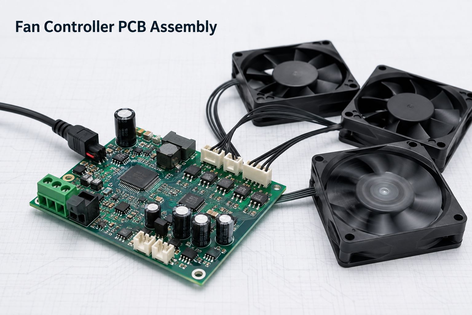
A reliable fan controller PCB assembly must do more than switch a fan on and off. It must tolerate startup current, maintain stable PWM control, read TACH feedback accurately, manage heat, and behave safely during fan stalls or cable faults. Before production, review the following 12 checks against the actual fan, power supply, firmware, enclosure, and test requirements.
12 Fan Controller PCB Assembly Checks at a Glance
- Confirm the fan interface and pinout.
- Check whether the input can handle startup current.
- Verify MOSFET temperature under real load.
- Review the complete PCB high-current path.
- Check whether PWM noise affects TACH feedback.
- Match input protection to the operating environment.
- Confirm connector polarity and orientation.
- Verify mechanical support for through-hole power parts.
- Complete firmware programming requirements.
- Test the PCBA with the actual fan load.
- Prepare complete RFQ and production files.
- Confirm the PCBA supplier can control these risks.
1. Which Fan Interface Must the PCBA Support?
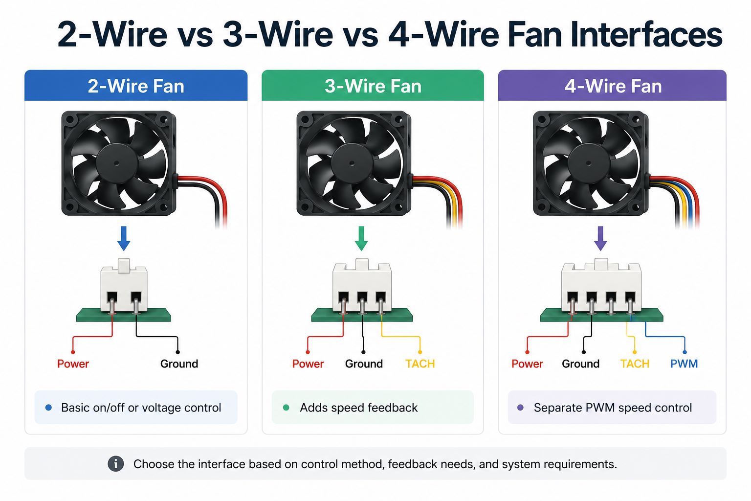
Start with the actual fan interface. A connector can fit mechanically while its pinout, signal voltage, or control method remains incompatible.
| Fan interface | Connections | Speed control | Speed feedback |
|---|---|---|---|
| 2-wire | Power, ground | Supply voltage or power switching | Usually unavailable |
| 3-wire | Power, ground, TACH | Supply voltage or power switching | Available |
| 4-wire | Power, ground, TACH, PWM | Dedicated PWM input | Available |
A 2-wire fan is simple, but reducing its supply voltage may affect low-speed startup. A 3-wire fan adds speed feedback. A 4-wire fan separates power delivery from PWM control and is more suitable for precise thermal management.
Confirm these points before layout:
- Rated voltage and operating range
- Connector and mating cable
- Pin sequence and polarity
- PWM logic level and frequency
- TACH output type and pull-up voltage
- Pulses per revolution
- Minimum reliable duty cycle
- Number of independently controlled channels
Do not rely on a generic fan pinout. Use the selected fan’s datasheet.
2. Can the Power Input Handle Fan Startup Current?
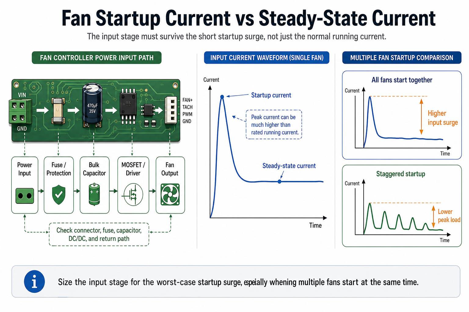
Fan rated current describes normal operation, not necessarily startup. When the rotor is stationary, the motor may briefly draw much more current.
For several fans starting together:
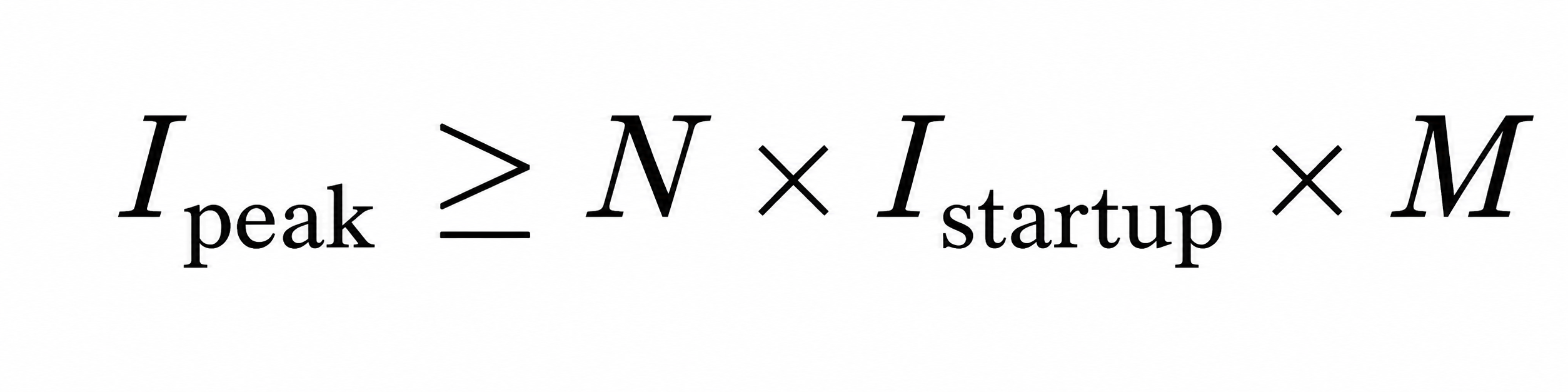
Where:
- N = number of fans
- Istartup = startup current per fan
- M)= design margin
For four fans drawing 1.2 A each at startup with a 25% margin:
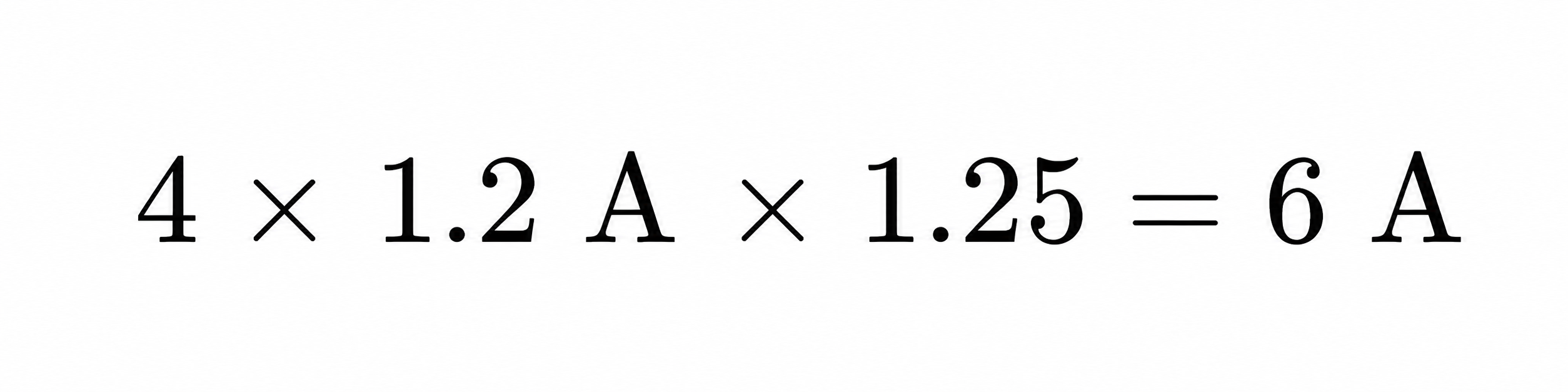
The complete input path must tolerate that peak, including the connector, fuse, protection devices, DC/DC converter, capacitors, current-sense parts, and return path.
A common failure occurs when several fans start together and pull the supply below the MCU brownout threshold. The controller resets, PWM disappears, and the startup cycle repeats.
Possible corrections include staggered startup, lower-resistance power paths, more appropriate bulk capacitance, and a power supply with stronger transient response.
3. Will the Switching MOSFET Overheat?
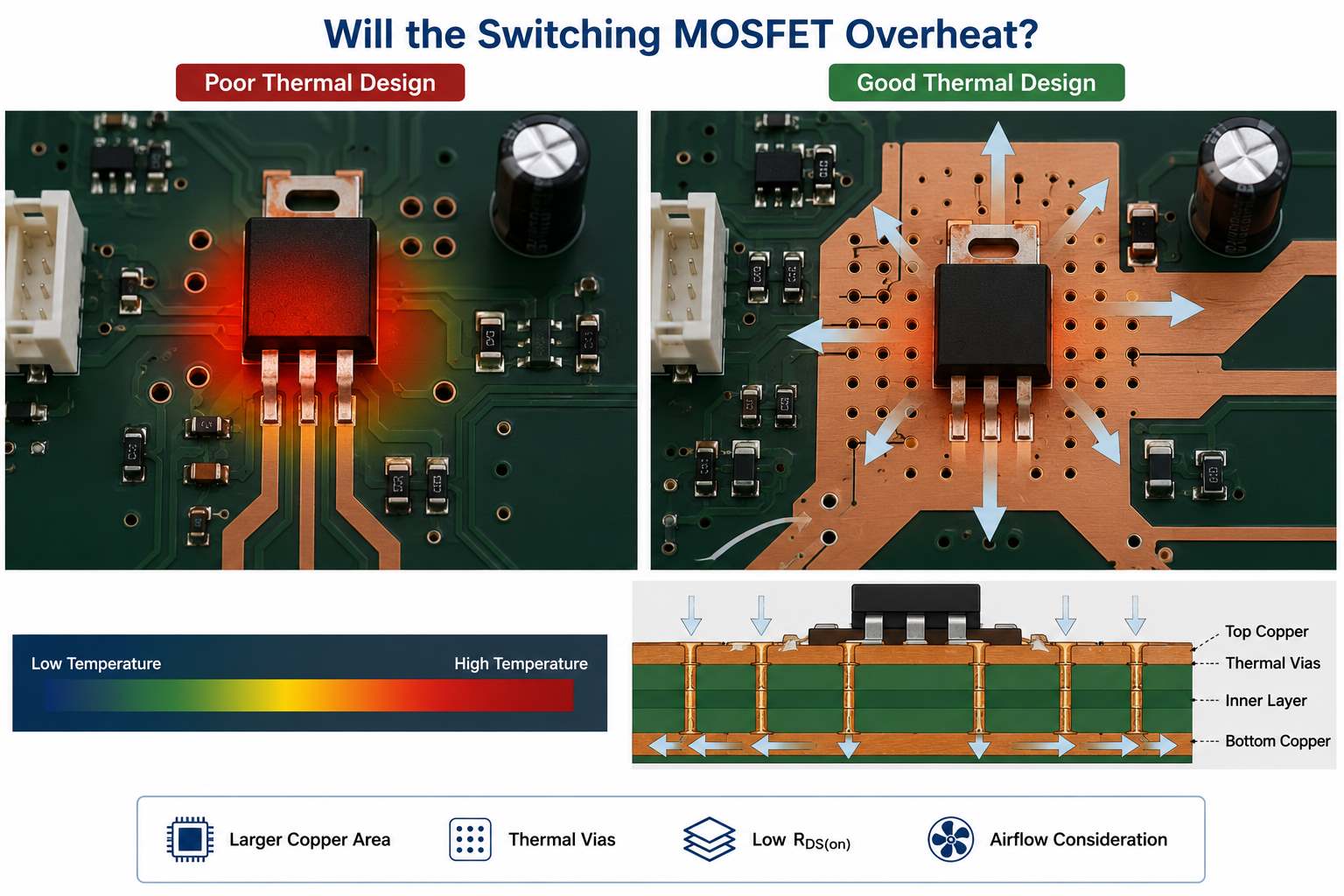
A MOSFET may satisfy its headline current rating and still overheat on the assembled board. Current ratings are often based on ideal thermal conditions that do not match a compact PCB inside an enclosure.
Its basic conduction loss is:
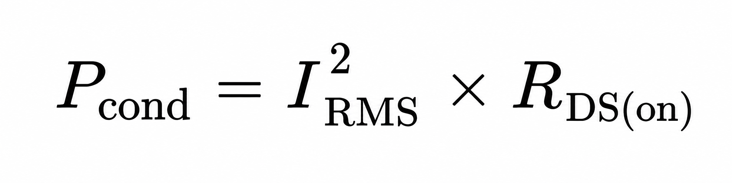
For 3 A through a MOSFET with an effective on-resistance of 25 mΩ:
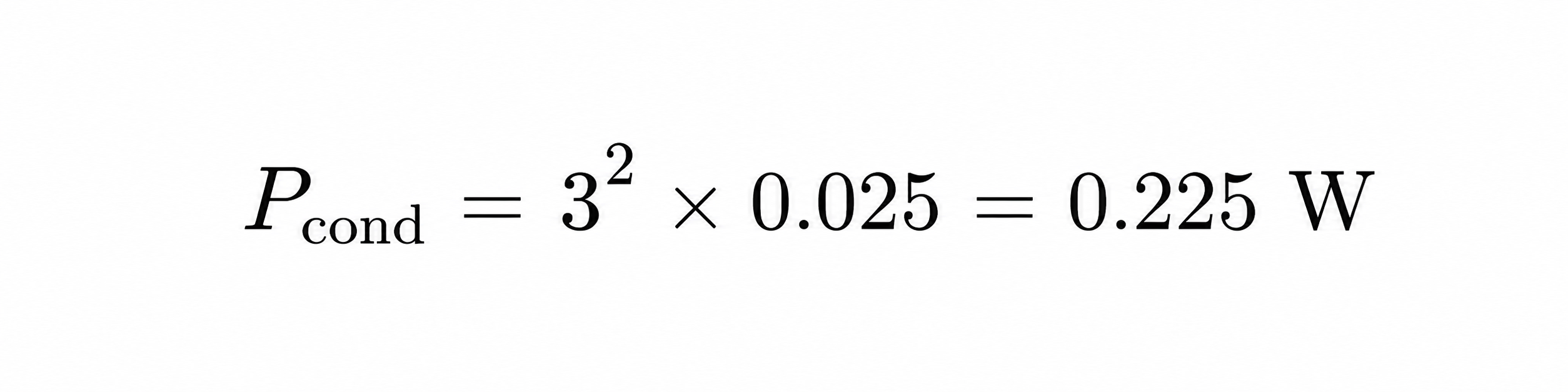
This excludes switching loss, gate-drive loss, nearby heat sources, and the rise in RDS(on) at higher junction temperatures.
Check:
- On-resistance at the actual gate voltage
- On-resistance at operating temperature
- PWM frequency and switching speed
- MOSFET package and thermal resistance
- Drain copper area and thermal vias
- Enclosure temperature
- Airflow direction
- Locked-rotor operating time
A device characterized at a 10 V gate voltage may perform poorly when driven by a 3.3 V MCU. Prototype temperature measurements should therefore be made under real load and enclosure conditions.
4. Can the PCB Power Path Carry the Required Current?
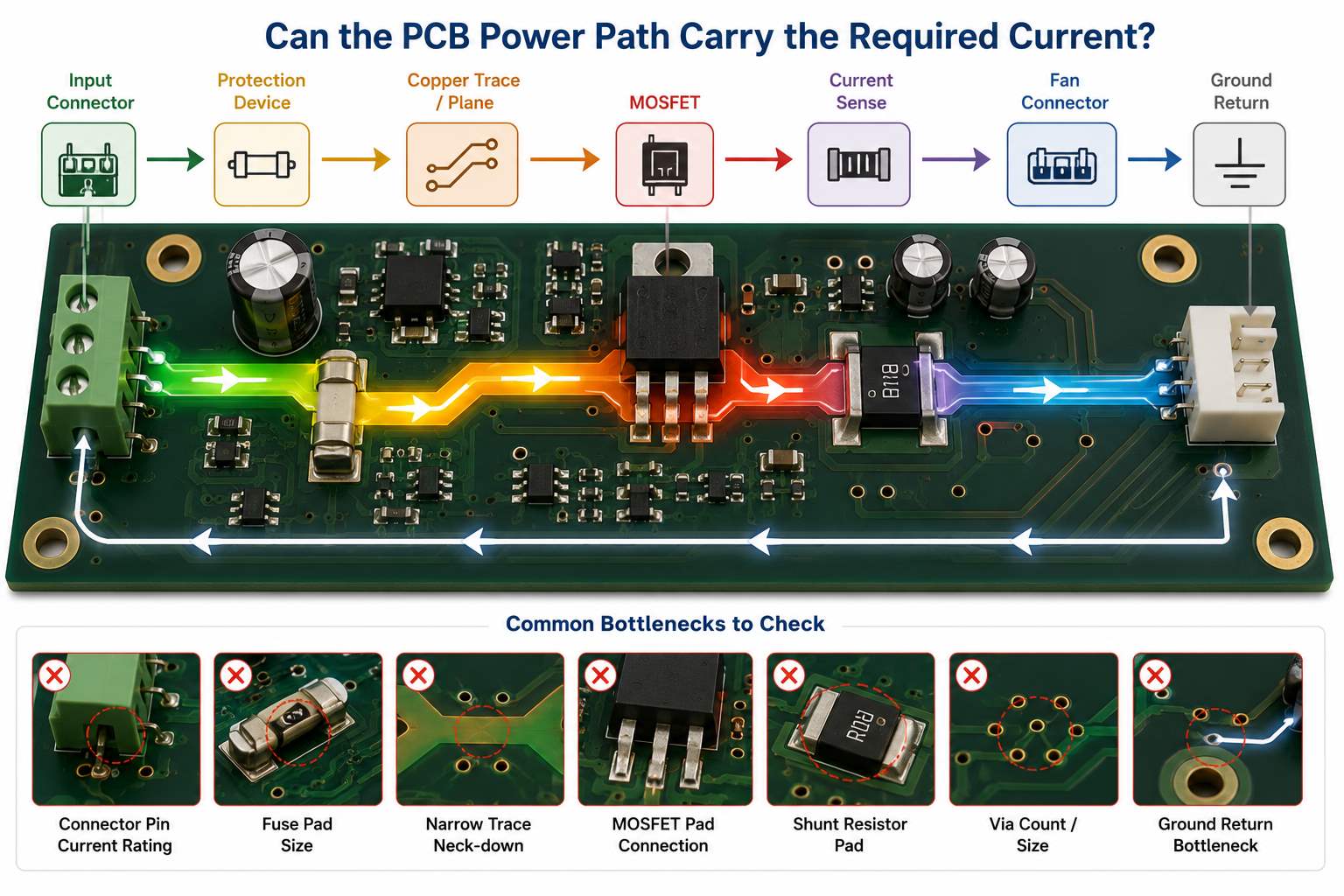
The power path is limited by its weakest section, not by its widest copper pour.
Review the complete route:
Input connector
→ Protection device
→ Copper trace or plane
→ MOSFET
→ Current-sense element
→ Fan connector
→ Ground return
Check both temperature rise and voltage drop:

At 4 A through a total path resistance of 80 mΩ:
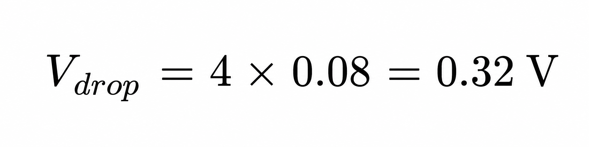
That drop may be significant in a low-voltage fan system.
Inspect connector pins, fuse pads, MOSFET connections, shunt-resistor pads, layer-transition vias, thermal reliefs, and narrow copper necks. Return paths deserve the same attention as positive supply traces.
Copper weight should be selected from current, trace geometry, allowable temperature rise, and voltage-drop limits. Higher-current boards may require wider pours, parallel layers, more vias, or 2 oz copper. Heavy copper alone will not correct an underrated connector or poor current-path layout.
5. Can PWM Switching Corrupt the TACH Signal?
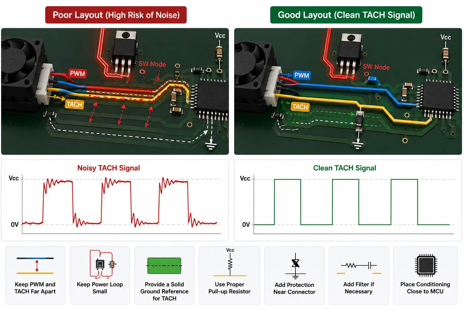
PWM edges can couple into the tachometer signal through parallel routing, shared return impedance, switching loops, or the fan cable. The result may be unstable RPM readings or false stall alarms.
The TACH signal path normally includes:
Fan TACH output
→ Connector
→ ESD protection
→ Pull-up
→ Filter or buffer
→ MCU input
Fan speed can be calculated from:
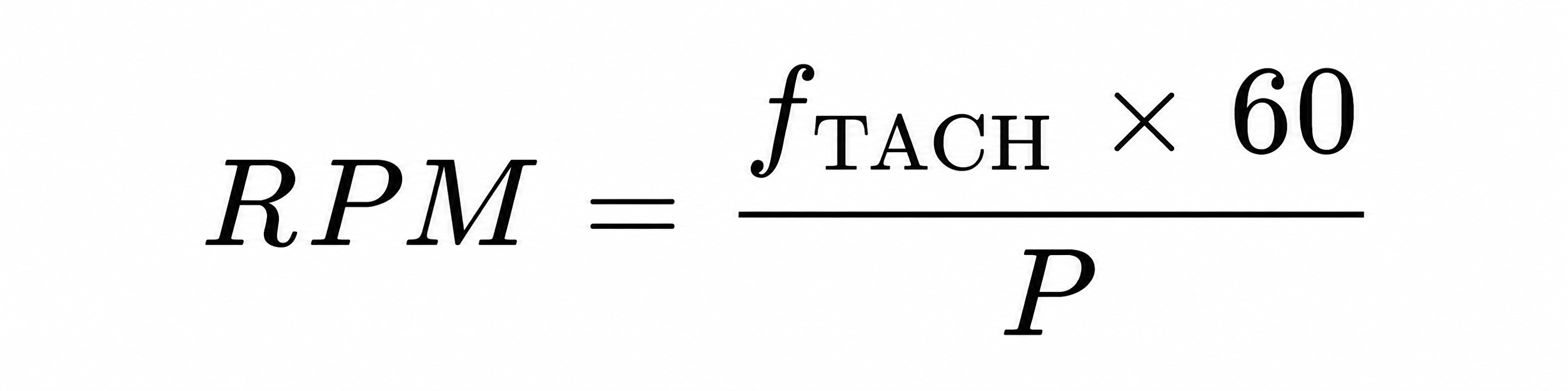
Where (P) is the number of pulses per revolution. If the fan provides two pulses per revolution:
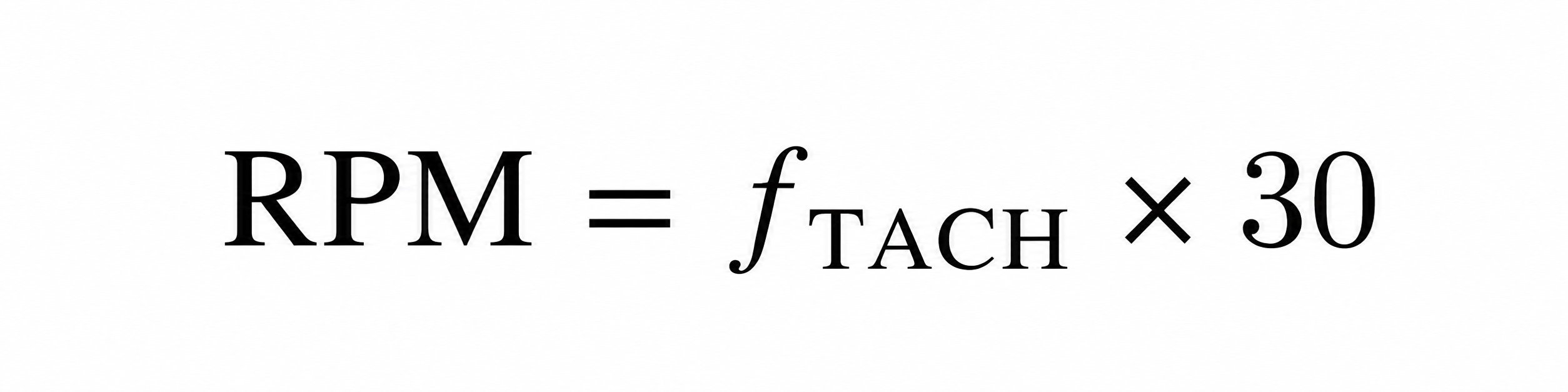
To protect signal integrity:
- Keep TACH away from MOSFET switching nodes
- Avoid long parallel routing with PWM
- Keep the gate-drive loop compact
- Provide a continuous TACH return path
- Place input conditioning near the MCU
- Add connector-side ESD protection
- Verify pull-up voltage and MCU thresholds
An RC filter may help, but excessive filtering can distort valid pulses at high speed. Verify the waveform with the fan connected across the full PWM range.
6. Does the Input Protection Match the Installation Environment?
Protection should reflect the actual installation rather than a generic circuit template.
| Environment | Protection to review |
|---|---|
| Indoor appliance | Fuse, reverse polarity, basic surge protection |
| Industrial 24 V system | TVS, overvoltage, EFT, reverse polarity |
| Long external cable | ESD, surge, cable-induced transients |
| Automotive supply | Reverse battery, load dump, cranking transients |
| Multi-fan power bank | Short circuit, overcurrent, thermal shutdown |
The protection network must coordinate the fuse, TVS diode, reverse-polarity device, input capacitor, and power converter. A TVS with insufficient pulse capability may fail, while a slow fuse may not protect the downstream MOSFET.
Review the expected fault conditions:
- Reversed supply
- Hot plugging
- Fan cable short circuit
- Locked rotor
- Supply overshoot
- ESD at external connectors
- Long-cable transients
- Incorrect field wiring
These functions should be verified during prototype testing rather than assumed from component selection alone.
7. Are Fan Connector Polarity and Orientation Unambiguous?
Connector errors can survive visual inspection and make an otherwise correct PCBA unusable.
The following documents must agree:
- Schematic
- PCB silkscreen
- BOM
- CPL file
- Assembly drawing
- Cable drawing
- Fan datasheet
- Test procedure
Document the pinout explicitly:
| Pin | Signal | Example condition |
|---|---|---|
| 1 | GND | Power return |
| 2 | VIN | Fan supply |
| 3 | TACH | Open-collector output |
| 4 | PWM | Fan control input |
The real sequence may differ, so it must be confirmed for each fan.
First-article inspection should verify Pin 1, connector keying, right-angle orientation, cable exit direction, CPL rotation, and mating-cable compatibility. Similar connectors placed close together should also be clearly differentiated.
8. Do Through-Hole Power Parts Have Enough Mechanical Support?
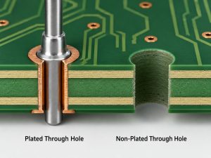
Fan control boards often contain through-hole connectors, relays, fuse holders, transformers, terminal blocks, and large capacitors. These parts experience cable pull, insertion force, vibration, and thermal cycling.
Review:
- Finished-hole diameter
- Lead-to-hole clearance
- Annular ring
- Pad dimensions
- Hole-wall copper
- Solder fill
- Component seating
- Board-edge clearance
- Mounting or retention features
A connector near the board edge can act as a lever and transfer cable force directly into its solder joints. Depending on the application, additional mounting holes, latches, brackets, larger pads, or controlled adhesive may be needed.
Wave or selective soldering parameters should also account for large thermal masses and ground-connected pins. The solder result should be inspected on the actual component rather than inferred from a standard process profile.
9. Are Firmware Programming Requirements Complete?
A HEX or BIN file alone is not a complete production instruction.
The programming package should define:
- Exact target MCU or memory
- Approved firmware file and revision
- Supported hardware revision
- SWD, JTAG, UART, ISP, or other interface
- Programming pinout and voltage
- Fuse bits, option bytes, or boot settings
- Checksum or read-back method
- Serialization rules
- Code-locking requirements
- Firmware label format
- Traceability records
Programming pads must remain accessible during production. When conformal coating is required, programming and testing should be completed before coating unless the process plan provides protected access.
Version control is particularly important when prototype builds use different fan curves, temperature thresholds, or fault-handling logic.
10. Does the Functional Test Use the Actual Fan Load?
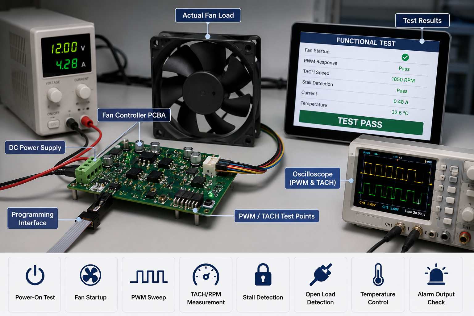
Voltage at an empty connector does not prove that a fan controller works. Functional testing should use the specified fan, an approved equivalent, or a validated load fixture.
| Test item | Required verification |
|---|---|
| Power-on | No reset or excessive current |
| Startup | Fan starts within the required time |
| PWM response | Speed follows duty-cycle changes |
| TACH feedback | Reported speed matches operation |
| Stall | Fault is detected correctly |
| Fan disconnect | Open-load alarm operates |
| Temperature input | Speed follows the programmed curve |
| Fail-safe mode | Fan enters the defined safe state |
A practical sequence is:
Power-on
→ Firmware check
→ Fan startup
→ PWM sweep
→ TACH verification
→ Fault simulation
→ Final pass/fail record
Acceptance limits should be measurable. “Fan spins” is not enough. A specification might define startup time, acceptable RPM tolerance, fault-detection delay, current limits, and recovery behavior.
For multi-channel boards, every output should be tested. Sampling one channel can miss assembly or firmware faults elsewhere.
11. Are the RFQ and Production Files Complete?
Incomplete files lead to inaccurate quotations, repeated engineering questions, and delayed production.
| File or specification | Purpose |
|---|---|
| Gerber or ODB++ | PCB fabrication |
| BOM | Component sourcing |
| CPL | SMT placement |
| Assembly drawing | Orientation and special notes |
| Schematic | Engineering and test review |
| Fan datasheet | Current, PWM, TACH, connector |
| Firmware package | Programming |
| Functional test procedure | Pass/fail criteria |
| Panel drawing | Assembly and depaneling |
| Coating drawing | Coverage and masking |
The BOM should contain manufacturer part numbers rather than generic descriptions such as “MOSFET” or “4-pin connector.”
The assembly drawing should identify connector orientation, Pin 1, polarized parts, do-not-fit positions, test points, programming pads, and coating exclusions.
Without the fan datasheet, the manufacturer cannot reliably review startup current, signal levels, connector compatibility, or load testing.
12. Can the PCBA Supplier Control These Production Risks?
A suitable supplier should be evaluated against the project’s specific risks, not a generic equipment list.
Check whether the supplier can:
- Assemble mixed SMT and through-hole components
- Provide SPI, AOI, and X-ray where applicable
- Review high-current and thermal areas before production
- Control connector orientation during first-article inspection
- Program the selected MCU with verification
- Track firmware versions by batch
- Test the PCBA with a real fan or approved load
- Verify PWM, TACH, startup, stall, and alarm functions
- Apply conformal coating with controlled masking
- Maintain PCB, component, firmware, and test traceability
For a fan control board PCB assembly, manufacturing capability means more than accurate component placement. The supplier must confirm that the power stage, fan interface, firmware, feedback signals, and protection functions operate together as a complete system.
FAQs About Fan Controller PCB Assembly
What is a fan controller PCB?
A fan controller PCB manages one or more fans through voltage control, PWM, temperature inputs, or feedback signals. It may also detect fan speed, stalls, overcurrent, and fan disconnection.
What is the difference between a fan controller PCB and PCBA?
The PCB is the bare circuit board. The PCBA includes the assembled components, connectors, programmed devices, and soldered parts required for fan control.
Can one fan controller operate several fans?
Yes, provided the input stage, copper path, connectors, switching devices, and power supply support the combined startup and operating current. The design must also define shared or independent PWM and TACH channels.
How should a fan controller PCBA be tested?
Testing should verify startup, PWM response, TACH feedback, fault detection, temperature response, and fail-safe behavior using the specified fan or a validated equivalent load.
What files are needed for a fan controller PCBA quotation?
Provide Gerber or ODB++, BOM, CPL, assembly drawing, schematic, fan datasheet, firmware, programming instructions, production quantity, and functional-test requirements.
Ready to build a custom fan controller PCB assembly or OEM industrial controller PCBA? Send your Gerber files, BOM, CPL, fan datasheet, firmware, and testing requirements to sales@bestpcbs.com. Our engineering team can review manufacturability, component availability, programming, connector orientation, and load-testing risks before production.