DC DC converter testing checks whether a power stage delivers the required voltage as its input, load, and operating temperature change. A correct reading at one operating point is only part of the picture. Startup waveforms, efficiency measurements, ripple, and load-step response show how the supply behaves when the conditions around it change.
EBest Circuit supports PCB fabrication, component assembly, and agreed functional testing for power electronics boards. Connecting assembly requirements with accessible test points helps make electrical checks practical on the finished PCBA. For a converter board prototype or production project, contact sales@bestpcbs.com to discuss manufacturing and test coverage.
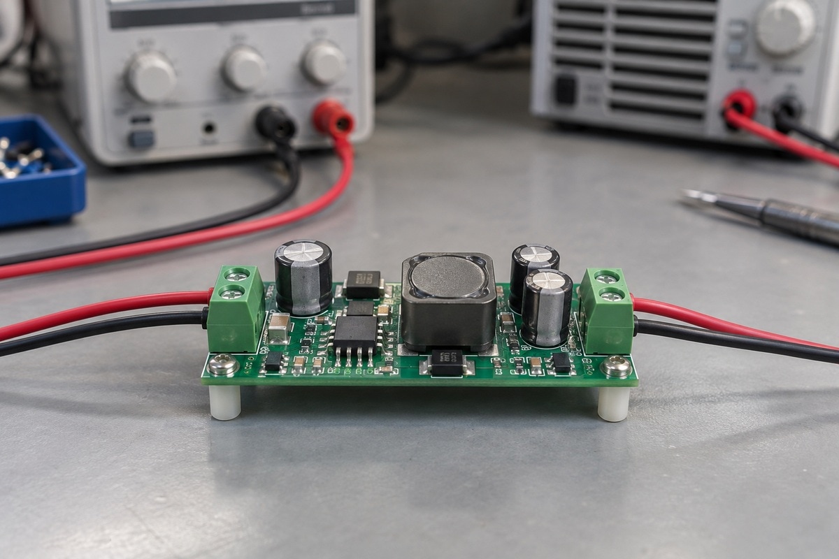
What Equipment Is Needed for DC DC Converter Testing?
A typical bench uses a controllable DC source, an electronic load, voltage and current measurement, and an oscilloscope. Each instrument answers a different part of the performance question.
| Equipment | Main use |
|---|---|
| Programmable DC supply | Apply input voltage and controlled input changes |
| Electronic load | Set output current and generate load steps |
| DMMs or a suitable power analyzer | Measure steady-state voltage, current, and power |
| Oscilloscope with suitable probes | Capture startup, ripple, and transient waveforms |
| Temperature sensors or thermal camera | Track heating during sustained operation |
Connect the source to the converter input and the load to its output. Measure voltage at the board terminals: readings at the supply or load can include cable losses. Separate sense connections can improve accuracy where the equipment supports them.
The instrument ratings must cover the intended voltage, current, power, and transient conditions. For floating or isolated nodes, use a suitable differential or isolated measurement arrangement; an earth-referenced scope ground can unintentionally connect circuit nodes to earth.
How Do You Check Startup and Shutdown Behavior?
Capture input voltage and output voltage together to see when the converter starts, how its output rises, and what happens when power is removed. Include enable or power-good signals when those functions are present.
- Apply the specified input transition. Start with the intended load connected and capture the complete output rise.
- Measure the startup interval. Use the trigger and voltage thresholds defined for the product so repeated measurements are comparable.
- Inspect the output peak. Compare overshoot and any interrupted rise with the permitted output limits.
- Remove input power or disable the converter. Observe output decay and any required sequencing behavior.
Input power removal and an enable command are separate events. Output capacitance and the connected load can also change the shutdown waveform.
A board that repeatedly tries to start may be reaching its own protection limit, or the bench supply may be limiting current. Looking at the input waveform helps distinguish these possibilities before changing the converter circuit.
How Do You Measure Line and Load Regulation?
Line regulation describes output variation as input voltage changes. Load regulation describes output variation as output current changes. Vary one condition at a time to separate the two effects.
| Test | Change | Keep fixed | Measure |
|---|---|---|---|
| Line regulation | Input voltage across the specified range | Output load | Settled output voltage at each input point |
| Load regulation | Output current across the specified range | Input voltage | Settled output voltage at each load point |
Use the datasheet’s calculation convention when comparing results. Some specifications express variation in millivolts, others as a percentage or a change per unit of input voltage or current.
For example, an output spread from 4.98 V to 5.02 V is 40 mV, equivalent to 0.8% of a nominal 5 V output. That calculation alone does not establish a pass: the allowed range, reference value, and test conditions still determine acceptance.
Measure at the specified output point. A voltage drop at a distant load may include wiring resistance even when the converter’s terminal voltage remains stable.
How Do You Measure Converter Efficiency and Temperature Rise?
Efficiency compares power delivered with power taken in at the same operating point. For steady DC conditions with small ripple, the usual calculation is:
Efficiency (%) = (VOUT × IOUT) ÷ (VIN × IIN) × 100
Use measurements at the converter terminals, with a clearly defined boundary for any auxiliary power. When voltage and current vary significantly, use a suitable instrument that averages instantaneous power rather than relying on the product of separate average readings.
Illustrative calculation. A board receiving 12 V at 0.95 A takes in 11.4 W. If it supplies 5 V at 2 A, it delivers 10 W. Its calculated efficiency is approximately 87.7%, with 1.4 W dissipated within the measured boundary.
Repeat measurements across the intended input and load range. A single peak-efficiency value does not describe light-load behavior or operation at another input voltage.
During sustained operation, record component temperatures together with ambient temperature, airflow, and mounting conditions. Temperature rise is the measured component temperature minus ambient temperature. Wait for the defined thermal steady-state condition before comparing results; a short power-on check does not reveal the final operating temperature.

How Do You Measure Output Ripple and Noise Accurately?
Probe connection and oscilloscope settings can materially change the observed waveform. A large probe loop may pick up switching interference and exaggerate the noise attributed to the output.
- Use the specified measurement point. This is often across the output capacitor or designated output terminals.
- Keep the measurement loop short. A ground spring or appropriate low-loop-area connection reduces pickup.
- Match the specified bandwidth and coupling. A 20 MHz limit is common in some ripple measurements, but the product’s test method takes priority.
- State the operating conditions. Record input voltage, output current, and any relevant operating mode alongside the peak-to-peak result.
Bandwidth-limited ripple and wider-band switching spikes are different measurements. Retain both where the application requires them, with the settings identified. A waveform captured under one bandwidth setting should not be compared directly with a limit defined under another.
For small signals, the probe and oscilloscope noise floor also matter. A reading close to that floor needs closer measurement review before it is attributed to the board.
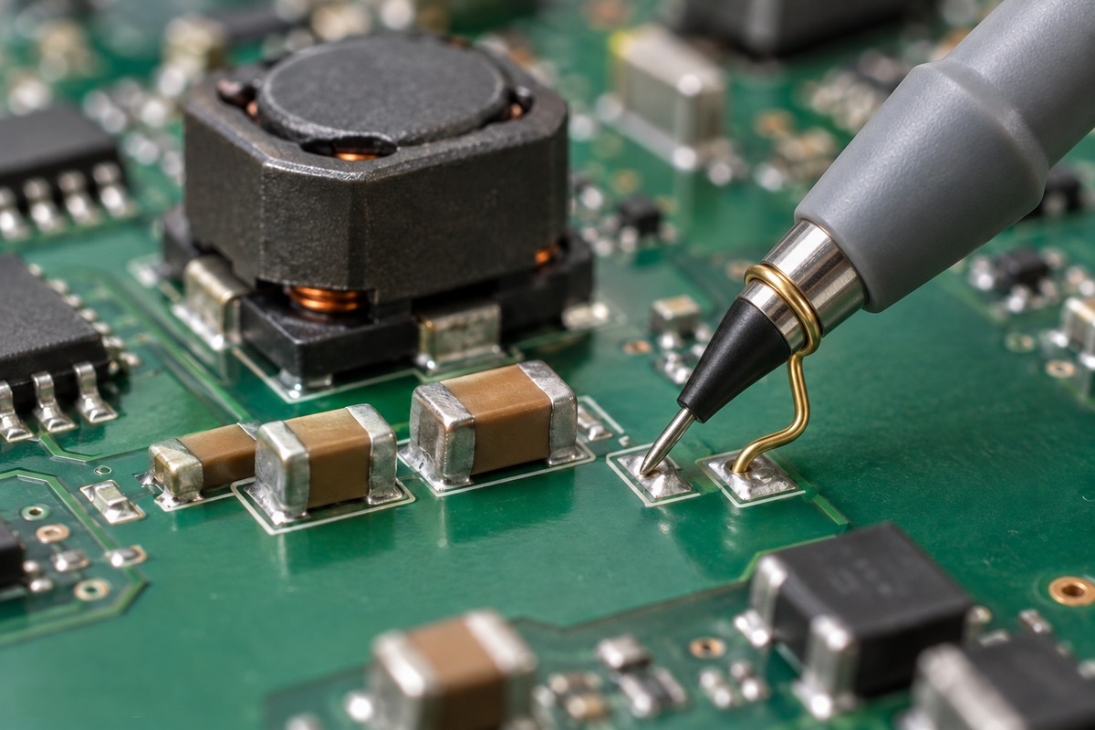
What Does a Load Transient Test Reveal?
A load transient test shows how far output voltage moves and how quickly it recovers when current demand changes. It can expose behavior that steady-state regulation measurements miss.
Set the initial current, final current, transition speed, and dwell time to represent the intended load. Capture the actual current waveform as well as output voltage; a programmed load setting does not by itself confirm the step achieved at the board.
| Waveform feature | Interpretation |
|---|---|
| Undershoot after a load increase | Output voltage falls while the converter responds to extra demand |
| Overshoot after a load decrease | Output voltage rises as the power stage adjusts to reduced demand |
| Settling time | Time taken to return to the specified voltage band |
| Ringing | A reason to investigate the control loop, input source, and interconnections |
Ringing at the output does not identify its cause by itself. Observe the input rail too: input-supply resonance can appear in the output response. Load-step speed and wiring can also affect the result.
Use the application’s permitted voltage excursion and recovery time for acceptance. A transient test can reveal stability concerns, while a quantitative gain-and-phase assessment requires the appropriate loop-response measurement.
How Do You Test Overcurrent Protection and Fault Recovery?
Test the protection threshold and the recovery sequence together. A converter may limit current, restart periodically, or remain off until it receives a reset, depending on its design.
- Begin within the normal operating range. Record input voltage, load current, and output voltage.
- Apply the defined overload. Follow the product’s permitted current, duration, and test procedure using suitably rated equipment.
- Observe the protection response. Capture the transition into current limiting or shutdown and any restart pulses.
- Remove the overload. Verify automatic recovery or apply the specified reset, then repeat normal output measurements.
An overload test and a short-circuit test are not interchangeable. Short-circuit testing needs a controlled setup and a procedure appropriate to the converter’s rating.
Keep enough capability in the input source to avoid confusing its current limit with the converter’s protection. Where undervoltage lockout is specified, measure turn-off and restart thresholds separately; their difference describes the input-voltage hysteresis.
FAQs About DC DC Converter Testing
Can you test a DC DC converter with a multimeter?
A multimeter can check steady input and output voltage and, with the correct connection and rating, current. An oscilloscope is needed to examine fast events such as startup overshoot, switching ripple, and load-step response.
Is the correct no-load output voltage enough to pass a converter?
It establishes only the result at that condition. Performance under load, during transitions, and after heating requires additional measurements. Some converters also specify minimum-load conditions.
What belongs in a DC DC converter test plan?
Include input and load conditions, measurement points, instrument settings, temperature conditions, test timing, and acceptance limits. For dynamic tests, define the transition speed and the voltage band used to measure recovery.
How does production testing differ from design validation?
Design validation explores performance across the intended operating range and relevant corner conditions. Production testing uses an agreed set of repeatable checks to identify manufacturing defects and verify selected functions on assembled boards. Passing that set does not replace complete design validation.
Do isolated DC DC converters need additional tests?
Isolation requirements can add dielectric-withstand and insulation-resistance testing. Test voltage, duration, connections, and acceptance criteria depend on the product specification and applicable requirements; ordinary output measurements do not verify the isolation barrier.
Effective DC DC converter testing connects each measurement to a defined operating condition and an acceptance limit. For PCB fabrication, assembly, and agreed functional testing of your converter board, contact EBest Circuit at sales@bestpcbs.com to discuss a prototype or production build.