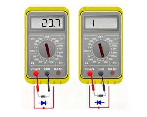
Positive and negative of diode describes the two polarity terminals of a diode: the anode and the cathode, which decide how current should pass through the component. This article explains how to identify diode polarity by checking the body marking, symbol, terminal direction, band marking, multimeter reading, Zener diode polarity, LED diode legs, and PCB Assembly orientation.
For many users, the hard part is not knowing that a diode has polarity. The real problem is checking the right side on a real component before it is soldered, tested, or assembled onto a PCB.
Are you facing these problems when checking the positive and negative of a diode?
- The diode has a band, but you are not sure whether it means positive or negative.
- The schematic symbol is clear, but the real diode package looks different.
- SMD diode markings are too small to read quickly.
- LED diode legs have been cut, so the long-leg clue is gone.
- A reversed diode may cause the PCBA to fail testing.
As a PCBA manufacturer, we reduce these risks by checking diode polarity from design review to final inspection.
- We confirm the anode and cathode before SMT assembly.
- We compare the schematic, BOM, footprint, and datasheet.
- We verify the diode band, SMD mark, and PCB silkscreen.
- We inspect LED polarity before and after soldering.
- We use AOI, visual inspection, and functional testing to catch wrong orientation.
EBest Circuit (Best Technology) is a professional PCB and PCBA manufacturer offering PCB fabrication, component sourcing, SMT assembly, through-hole assembly, inspection, and functional testing. For diode-related PCB Assembly, we help customers confirm polarized components, reduce orientation mistakes, and improve first-pass yield from prototype to production. For PCB or PCBA projects, pls feel free to contact us at sales@bestpcbs.com.
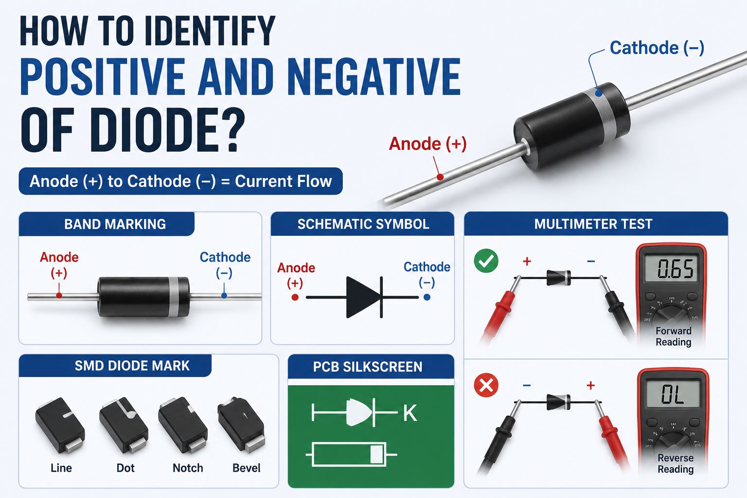
What Are the Positive and Negative of Diode?
The positive and negative of diode usually refer to its anode and cathode. In practical identification, the anode is commonly treated as the positive side, and the cathode is commonly treated as the negative side when the diode is forward-biased.
A diode is a directional component. It allows current to pass mainly in one direction and blocks current in the opposite direction. This is why diode polarity matters in power circuits, signal circuits, LED circuits, rectifier circuits, and PCB Assembly.
| Diode Part | Common Polarity | Practical Meaning |
|---|---|---|
| Anode | Positive side | Current enters in forward bias |
| Cathode | Negative side | Usually marked by a band |
| Band marking | Cathode side | Shows the negative end in most common diodes |
| Forward bias | Anode higher than cathode | Diode conducts |
| Reverse bias | Cathode higher than anode | Diode blocks current |
The simple rule is this: anode = positive side, cathode = negative side in normal diode polarity identification. However, in real circuits, voltage conditions can vary, especially in Zener diode applications. That is why it is safer to identify the anode and cathode rather than only saying “left side” or “right side.”
In short, identifying the positive and negative of diode starts with understanding anode and cathode.
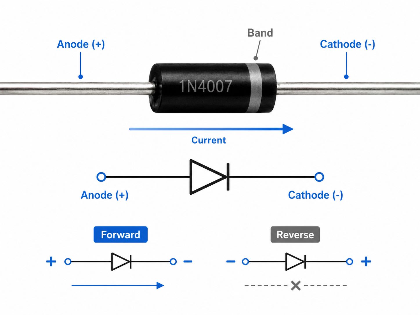
Positive and Negative of a Diode: What Do Anode and Cathode Mean?
The positive and negative of a diode are more accurately described as anode and cathode. These two terms are used in schematics, datasheets, PCB footprints, assembly drawings, and inspection documents.
The anode is the terminal where conventional current enters the diode during forward conduction. The cathode is the terminal where conventional current leaves the diode. On many standard diodes, the cathode side is marked with a stripe or band.
Key points to remember:
- Anode: positive side in forward-bias identification.
- Cathode: negative side in forward-bias identification.
- Current direction: usually from anode to cathode.
- Body marking: band usually marks the cathode.
- Schematic symbol: the vertical bar represents the cathode.
This matters because a diode is not like a resistor. A resistor can usually be installed in either direction. A diode cannot. If the diode direction is wrong, the circuit may block current when it should conduct, or fail to protect the circuit when reverse voltage appears.
For repair, prototyping, and PCB Assembly, the correct approach is to locate the anode and cathode first. After that, you can decide how the positive and negative terminals should connect in the circuit.
So, anode and cathode are not just textbook terms. They are the practical language used to control diode direction.
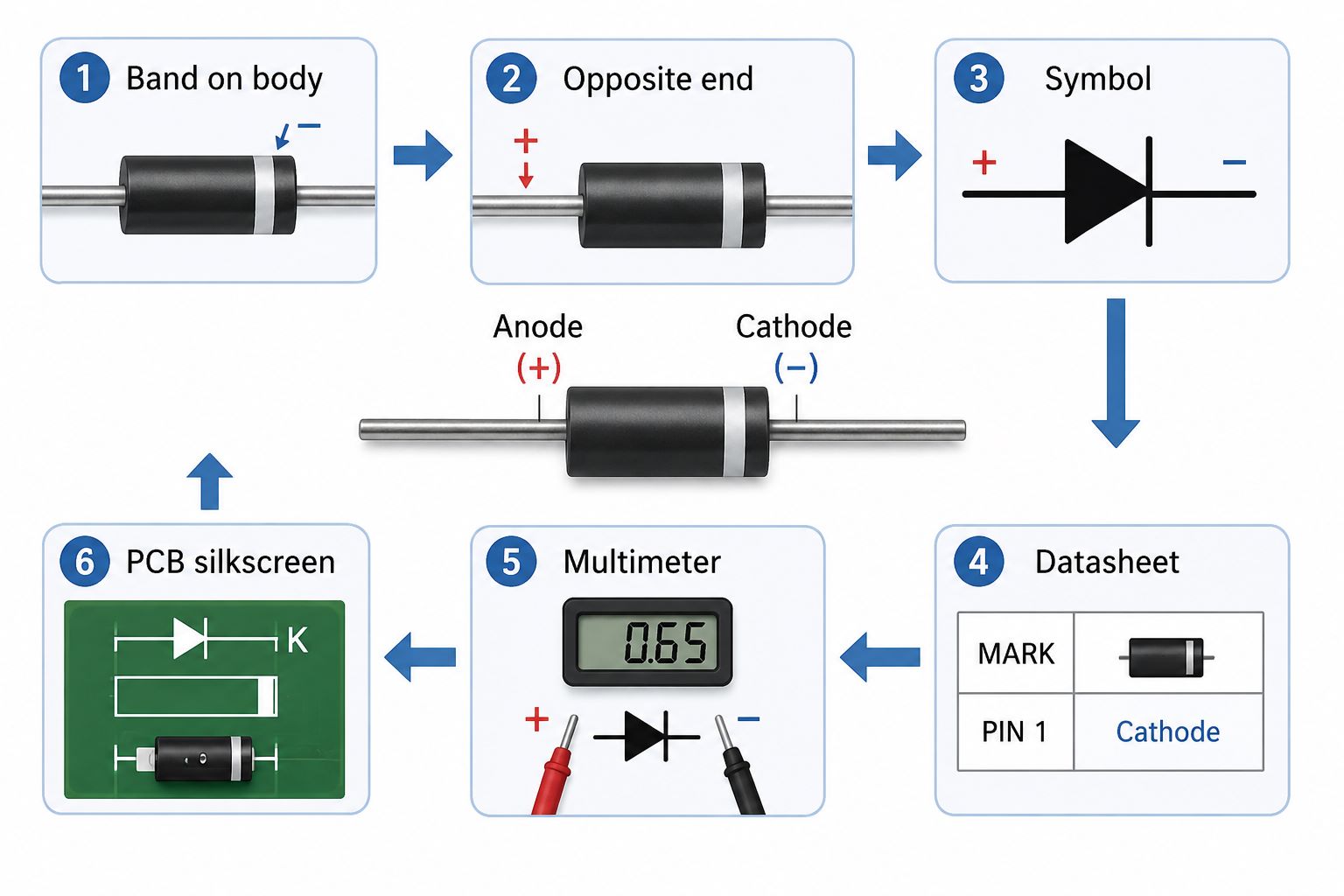
How to Identify Positive and Negative of Diode?
To identify positive and negative of diode, check the diode marking first, then confirm it with the schematic symbol, datasheet, PCB silkscreen, or multimeter. This layered method is more reliable than relying on only one clue.
A practical method includes the following steps:
- Look for the band on the diode body
The band usually marks the cathode, which is commonly treated as the negative side. - Find the opposite end
The end without the band is usually the anode, which is commonly treated as the positive side. - Check the diode symbol
In the schematic symbol, the vertical line shows the cathode. - Use the datasheet for special packages
SMD diodes, bridge rectifiers, Zener diodes, and LED diodes may use different package marks. - Use a multimeter diode mode
A normal forward voltage reading can confirm the direction. - Compare with the PCB silkscreen
The PCB may show a cathode bar, “K” mark, line mark, or diode outline.
For common axial diodes, the band marking is usually enough for quick identification. For production work, it is better to confirm the diode polarity through controlled documents. This includes the BOM, datasheet, PCB footprint, and assembly drawing.
The best answer to “how to identify positive and negative of diode” is not one single trick. It is a checking process: band, symbol, datasheet, multimeter, and PCB mark.
How to Identify Positive and Negative Terminal of Diode?
To identify positive and negative terminal of diode, focus on the actual connection points: leads, pads, or pins. The body shape may change, but the anode and cathode still define the polarity.
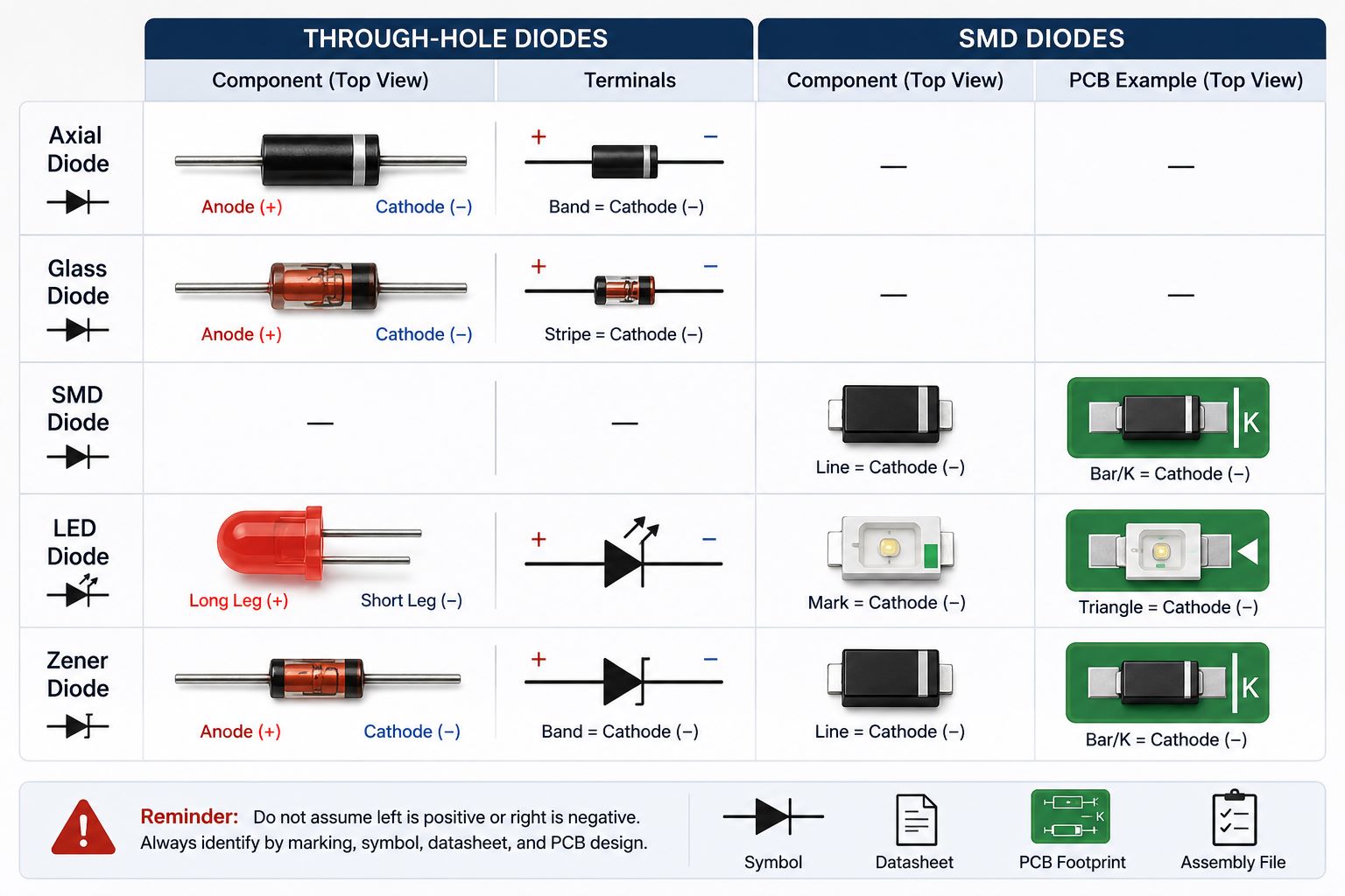
For a through-hole axial diode, there are two metal leads. The lead near the band is usually the cathode terminal. The opposite lead is usually the anode terminal.
For an SMD diode, there are usually two metal pads at the ends of the package. The cathode side may be marked with a line, dot, notch, bevel, or printed code. Since SMD package marks are small and not always easy to read, the datasheet should be checked before PCB Assembly.
| Diode Type | Positive Terminal | Negative Terminal | Best Check Method |
|---|---|---|---|
| Axial diode | Anode lead | Cathode lead | Band marking |
| Glass diode | Anode end | Cathode end | Colored stripe |
| SMD diode | Anode pad | Cathode pad | Package mark + datasheet |
| LED diode | Long leg often anode | Short leg often cathode | Leg length + flat edge |
| Zener diode | Anode | Cathode | Band + schematic function |
A common mistake is assuming the left terminal is positive or the right terminal is negative. This is unreliable because the diode can be rotated in the schematic, placed in different orientations on a PCB, or supplied in different packages.
For manual checking, identify the physical terminal first. For PCBA manufacturing, confirm that terminal against the PCB footprint and assembly file.
In simple terms, the positive terminal is usually the anode, and the negative terminal is usually the cathode, but the package marking must guide the final decision.
Positive and Negative Side of a Diode: Which Side Is Which?
The positive and negative side of a diode can usually be identified by checking the banded side and the unmarked side. On many standard diodes, the banded side is the cathode, and the unmarked side is the anode.
This is the fastest visual rule for common rectifier diodes, switching diodes, and signal diodes.
Use these clues:
- Banded side: usually cathode, negative side.
- Unmarked side: usually anode, positive side.
- Symbol bar side: cathode side in the schematic.
- PCB bar mark: usually shows cathode placement.
- “K” mark: often means cathode.
- “A” mark: often means anode.
However, not every diode gives you a large, clear stripe. Some SMD diodes have small laser markings. Some LED diodes use a flat edge. Some Zener diodes are used in reverse-bias circuits, which may confuse beginners.
When the marking is unclear, do not guess. Use a multimeter or check the datasheet.
The practical rule is simple: the banded side is usually the negative side, but the datasheet is the final reference when the package is unfamiliar.
How to Determine Positive and Negative of Diode with Band Marking and a Multimeter?
To determine positive and negative of diode more confidently, use both the band marking and a multimeter. The band gives a fast visual clue, while the multimeter gives an electrical confirmation.
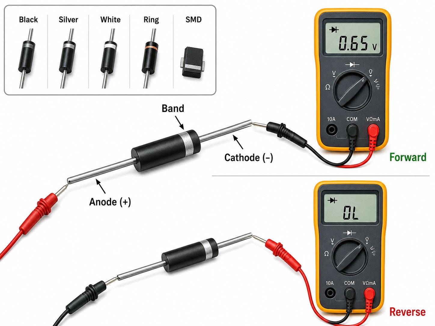
For most common diodes, the band marking shows the cathode. The opposite side is the anode. This is useful when the diode is new, clean, and easy to read.
Common marking types include:
- Black band: often marks the cathode.
- Silver band: often marks the cathode on rectifier diodes.
- White band: often marks the cathode on some packages.
- Colored ring: may mark the cathode.
- SMD line mark: often marks the cathode side.
When the marking is unclear, use the diode mode on a multimeter.
A basic multimeter check works like this:
- Set the multimeter to diode mode.
- Touch the red probe to one side of the diode.
- Touch the black probe to the other side.
- If the meter shows a forward voltage reading, the red probe is on the anode and the black probe is on the cathode.
- Reverse the probes. The meter should usually show OL or no conduction.
Typical forward voltage readings may be around 0.6 V to 0.7 V for many silicon diodes. Schottky diodes may show a lower value. LED diodes may show a higher value depending on color and material.
This method is especially helpful when the diode has no readable marking, has been removed from an old board, or is too small for quick visual inspection.
So, band marking is the fastest method, but multimeter testing is the safer confirmation.
Positive and Negative of Zener Diode: Is It Different from a Regular Diode?
The positive and negative of Zener diode are identified with the same basic polarity terms as a regular diode: anode and cathode. The cathode is usually marked with a band.
The main difference is how the Zener diode is used in a circuit. A regular diode is commonly used for rectification or one-way current flow. A Zener diode is often used in reverse bias for voltage regulation or voltage reference.
| Item | Regular Diode | Zener Diode |
|---|---|---|
| Terminals | Anode and cathode | Anode and cathode |
| Band marking | Cathode | Cathode |
| Common function | Rectification, protection | Voltage regulation |
| Forward direction | Conducts like a diode | Conducts like a diode |
| Reverse use | Usually blocks | Works at Zener voltage |
This is why Zener diode polarity can feel confusing. In many voltage regulation circuits, the Zener diode cathode connects toward the positive supply, while the anode connects toward ground. This does not mean the cathode becomes the anode. It only means the Zener diode is being used in reverse-bias operation.
To identify positive and negative terminal of Zener diode correctly, check four things:
- Cathode band on the body.
- Zener diode schematic symbol.
- Circuit connection direction.
- Zener voltage value in the datasheet.
For PCB Assembly, Zener diode polarity must be checked carefully because it may look “opposite” to a regular forward-biased diode circuit.
The marking rule is similar, but the circuit function is different.
Positive and Negative of LED Diode: How to Check the Legs and Direction?
The positive and negative of LED diode are also based on anode and cathode polarity. The LED lights only when current flows in the correct direction from anode to cathode.
For a new through-hole LED, the longer leg is usually the anode, and the shorter leg is usually the cathode. The flat edge on the LED body usually marks the cathode side. Inside many clear LEDs, the larger internal metal plate is also connected to the cathode.
Quick LED polarity clues:
- Long leg: usually positive, anode.
- Short leg: usually negative, cathode.
- Flat edge: usually cathode side.
- Larger internal cup: usually cathode.
- PCB “+” mark: usually anode pad.
- PCB bar or flat mark: often cathode pad.
For SMD LEDs, there are no long legs. You need to check the package mark, reel direction, datasheet, and PCB footprint. Some SMD LEDs use a dot, notch, triangle, green mark, or bottom-side mark to show polarity.
The positive and negative direction of a LED diode is important because a reversed LED usually will not light. In high-voltage or high-current conditions, reverse stress may also damage the LED.
For LED-related PCB Assembly, polarity should be checked before placement, after placement, and during functional testing. This is important for LED indicators, display boards, control panels, lighting modules, and consumer electronics.
The best method is to combine visual clues, datasheet confirmation, and electrical testing.
What Happens If You Check Positive and Negative of a Diode Incorrectly Before PCB Assembly?
If you check positive and negative of a diode incorrectly before PCB Assembly, the component may be placed in the wrong direction. This can cause circuit failure, test failure, rework, or product reliability problems.
The exact result depends on the diode function in the circuit.
| Diode Application | If Polarity Is Wrong |
|---|---|
| Rectifier circuit | Output may be missing or unstable |
| LED indicator | LED may not light |
| Reverse protection | Protection may fail |
| Zener regulation | Voltage may not be regulated |
| Signal circuit | Signal path may be blocked |
| Flyback diode | Relay or coil protection may fail |
Common polarity mistakes include:
- Misreading the band
Some users think the band is the positive side. In most common diodes, it marks the cathode. - Ignoring the schematic symbol
The vertical bar in the diode symbol must match the cathode side. - Trusting unclear silkscreen only
PCB silkscreen can be helpful, but it should be checked against the datasheet and footprint. - Mixing diode package types
Axial diodes, SMD diodes, Zener diodes, and LED diodes may use different visual clues. - Skipping first article inspection
A wrong diode direction may repeat across an entire batch if the first board is not checked carefully.
For professional PCB Assembly, diode polarity should be verified before mass production. A good check process includes schematic review, BOM verification, datasheet comparison, footprint review, first article inspection, AOI, and functional testing.
This is why checking diode positive and negative is not only a small component task. It is part of production quality control.
FAQs About Positive and Negative of Diode
1. What is the positive side of a diode?
The positive side of a diode is usually the anode during forward-bias identification.
2. What is the negative side of a diode?
The negative side of a diode is usually the cathode. On many diodes, the cathode is marked with a band.
3. Is the band on a diode positive or negative?
The band usually marks the cathode, which is commonly treated as the negative side.
4. How do I identify positive and negative of diode quickly?
Check the band first. The banded end is usually the cathode, and the opposite end is usually the anode.
5. How do I identify positive and negative terminal of diode with a multimeter?
Use diode mode. When the red probe is on the anode and the black probe is on the cathode, the meter usually shows a forward voltage reading.
6. What does OL mean when testing a diode?
OL usually means the diode is not conducting in that direction. Reverse the probes to check the other direction.
7. Is the cathode always negative?
For simple identification, the cathode is usually called the negative side. In actual circuits, voltage conditions can vary, especially in Zener diode circuits.
8. How do I find positive and negative of an SMD diode?
Check the line, dot, notch, package code, PCB silkscreen, and datasheet. Do not rely on package shape alone.
9. How do I identify positive and negative of LED diode?
For through-hole LEDs, the long leg is usually anode, and the short leg is usually cathode. The flat edge usually marks the cathode side.
10. What happens if a diode is installed backwards?
The circuit may not work correctly. LEDs may stay off, rectifiers may fail, and the PCBA may not pass functional testing.
11. Is Zener diode polarity the same as regular diode polarity?
The anode and cathode marking is similar, but the Zener diode is often used in reverse bias for voltage regulation.
12. Can I rely only on PCB silkscreen to place a diode?
No. PCB silkscreen is useful, but it should be checked with the schematic, footprint, BOM, datasheet, and assembly drawing.
On the whole, positive and negative of diode helps users identify the anode, cathode, body marking, terminal direction, and correct PCB placement before using or assembling the component. This article explained diode polarity, anode and cathode meaning, visual identification, terminal checking, band marking, multimeter testing, Zener diode polarity, LED diode direction, and PCB Assembly risks.
The safest way to identify diode polarity is to combine the band marking, schematic symbol, datasheet, multimeter reading, PCB footprint, and production inspection.
EBest Circuit (Best Technology) provides professional PCB fabrication, PCBA assembly, component sourcing, PCB SMT assembly, through-hole assembly, AOI inspection, visual inspection, and functional testing. We help customers reduce diode polarity mistakes and improve assembly reliability from prototype to mass production. For your next PCB or PCBA project, pls feel free to contact EBest Circuit (Best Technology) at sales@bestpcbs.com.