A mylar capacitor may look like a low-risk line item in a BOM, but it can still delay production when the value marking, voltage rating, lead spacing, body size, or approved alternate is not clear. In real PCBA work, a part listed as “0.1 uF Mylar capacitor” may be electrically close, but still cause sourcing delay, footprint mismatch, enclosure interference, polarity confusion, or rework if the details are not checked before assembly.
EBest Circuit (Best Technology) supports PCB and PCBA projects with BOM review, component sourcing, DFM checking, SMT assembly, inspection, testing coordination, and small-batch production under one workflow. With about 20 years of PCB/PCBA manufacturing experience, our team can help engineers review Mylar capacitors, polyester film capacitors, unclear markings, approved alternates, footprint fit, and assembly notes before production starts. If your BOM includes capacitor replacement risks or unclear component specifications, please send your Gerber files, BOM, CPL, assembly drawing, and project notes to sales@bestpcbs.com for engineering review.
What Is a Mylar Capacitor?
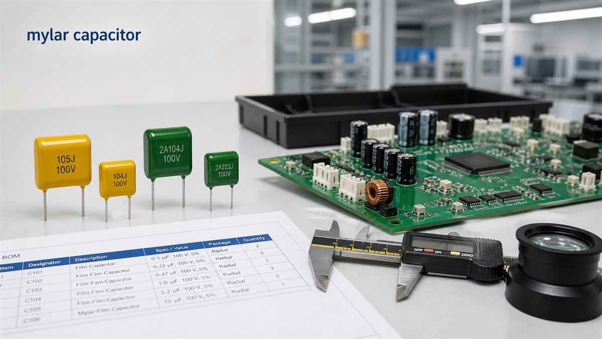
A mylar capacitor is a film capacitor that uses polyester film as the dielectric material. In electronics, "Mylar" is often used as a common name for polyester film capacitors, although Mylar itself is a brand name for a type of polyester film.
Mylar capacitors are widely used because they are stable, affordable, non-polarized in most cases, and suitable for many general electronic circuits. They are often found in signal coupling, filtering, timing circuits, audio circuits, consumer electronics, power adapters, and control boards.
For PCB and PCBA projects, the important point is not only the capacitor value. The assembly team also needs to confirm the package, lead spacing, voltage rating, body size, tolerance, temperature rating, and approved part number.
Mylar Capacitors vs Polyester Capacitors
In most practical electronics discussions, mylar capacitors and polyester capacitors refer to the same general capacitor type. Both usually mean a capacitor made with polyester film dielectric.
The naming difference often appears in BOMs, datasheets, supplier catalogs, or older maintenance documents.
| Term | Practical Meaning |
| Mylar capacitor | Common name used in many BOMs and repair documents |
| Polyester capacitor | More material-specific term |
| PET film capacitor | Technical material description |
| Metallized polyester capacitor | Polyester film capacitor with metallized electrode structure |
For purchasing and PCBA assembly, the safer approach is to confirm the manufacturer part number instead of relying only on the words "Mylar" or "polyester." Two capacitors may have the same capacitance value but different voltage ratings, tolerances, lead spacing, body sizes, and temperature performance.
Mylar Film Capacitor Structure and Lead Style
A mylar film capacitor usually has thin polyester film as the dielectric layer. Depending on the construction, the electrode may use foil or metallized film. The capacitor body is commonly dipped, boxed, or wrapped, with radial leads for through-hole PCB assembly.
Important physical details include:
- capacitance value
- voltage rating
- tolerance
- lead spacing
- body length
- body height
- body thickness
- lead diameter
- coating or case type
- temperature rating
For PCBA assembly, lead spacing is especially important. If the BOM lists the correct capacitance but the selected capacitor does not fit the PCB footprint, the assembly may need rework or part replacement before production can continue.
How to Read Mylar Capacitor Values Correctly?
Mylar capacitor values may be printed in several ways. Some use direct capacitance values such as 0.1 uF, 100 nF, or 10 nF. Others use a three-digit code.
A common code format works like this:
| Marking | Meaning |
| 104 | 100,000 pF = 100 nF = 0.1 uF |
| 103 | 10,000 pF = 10 nF = 0.01 uF |
| 472 | 4,700 pF = 4.7 nF |
| 224 | 220,000 pF = 220 nF = 0.22 uF |
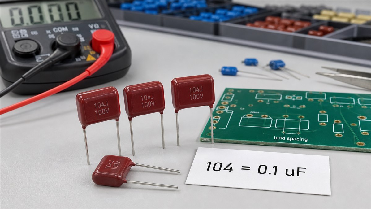
The first two digits are significant numbers. The third digit tells how many zeros to add in picofarads.
This is where mistakes often happen. A buyer may read "104" as 104 pF, but in capacitor coding it usually means 100,000 pF. For PCBA projects, the BOM should not rely only on a short printed code. A clear BOM should include the full capacitance value, voltage rating, tolerance, package type, and approved part number.
104 Mylar Capacitor and 0.1 uF Mylar Capacitor
A 104 Mylar capacitor is commonly a 0.1 uF Mylar capacitor. It may also be written as 100 nF or 100,000 pF.
These values are equivalent:
| Marking | Equivalent Value |
| 104 | 0.1 uF |
| 104 | 100 nF |
| 104 | 100,000 pF |
A 0.1 uF Mylar capacitor may be used for filtering, coupling, bypassing, timing, or general signal circuits, depending on the circuit design.
However, replacement should not be based on capacitance alone. The voltage rating, tolerance, lead spacing, body size, temperature rating, and application environment should also be checked. A capacitor with the same 0.1 uF value may still be unsuitable if it cannot fit the PCB or meet the circuit requirement.
Are Mylar Capacitors Polarized?
Most Mylar capacitors are not polarized. This means they usually do not have a fixed positive or negative lead like many electrolytic capacitors.
That is one reason Mylar capacitors are useful in AC signal paths, coupling circuits, filtering circuits, and other applications where polarity may change.
Even so, the assembly team should still check the actual datasheet and BOM requirement. Some film capacitor packages may have markings related to outside foil, shielding, tolerance, series, or voltage, and these markings should not be confused with polarity marks.
For PCBA inspection, the key point is simple: do not assume polarity based only on capacitor appearance. Confirm the capacitor type, datasheet, and assembly drawing before production.
What Are Mylar Capacitors Used For?
Mylar capacitors are used in many electronic products because they offer stable performance for general circuit needs.
Common uses include:
- signal coupling
- audio circuits
- timing circuits
- filtering
- bypassing
- control boards
- consumer electronics
- lighting products
- power adapters
- small industrial modules
In PCB manufacturing and assembly, the application affects what needs to be checked. A capacitor used in a low-voltage signal circuit may have different requirements from one used near heat, high voltage, vibration, or a crowded enclosure.
That is why a BOM should provide more than "Mylar capacitor." It should define the exact electrical and mechanical requirements so the selected part can be purchased and assembled correctly.
Film Capacitor vs Ceramic Capacitor in Replacement
A film capacitor and a ceramic capacitor may sometimes have the same capacitance value, but they are not always interchangeable.
| Item | Film Capacitor | Ceramic Capacitor |
| Dielectric | Plastic film | Ceramic material |
| Polarity | Usually non-polarized | Usually non-polarized |
| Stability | Often good for signal use | Depends on dielectric type |
| Size | Often larger | Often smaller |
| Mounting | Often through-hole or box type | Often SMD |
| Replacement risk | Footprint and body size | Voltage bias and dielectric behavior |
For replacement, the question is not only "Can I match the capacitance?" The better question is whether the capacitor still meets the circuit function, voltage requirement, temperature condition, PCB footprint, assembly method, and reliability expectation.
EBest Circuit does not replace the customer's circuit design team. The final capacitor type should come from the customer's engineering approval. Our role is to help check whether the approved component information matches the PCB footprint, BOM, sourcing plan, and assembly process.
How to Test Mylar Capacitor Before PCBA?
A Mylar capacitor can be checked before PCBA when the project requires component verification or when the part comes from an alternate source.
Possible checks include:
- capacitance measurement
- visual inspection
- lead spacing check
- body size check
- voltage rating confirmation
- part marking review
- BOM and datasheet comparison
- approved alternate confirmation
For normal production, component testing depends on the project requirement, part source, and quality control plan. In many cases, the first step is not advanced testing. It is making sure the BOM, datasheet, package, and PCB footprint all agree before SMT or through-hole assembly starts.
If a capacitor-heavy board has unclear markings or mixed replacement parts, early review can prevent assembly delays and unnecessary rework.
Why EBest Circuit Checks Capacitor Details Before PCBA
Capacitor issues may look small on paper, but they can stop production quickly. A wrong value, wrong voltage rating, wrong package, wrong lead spacing, or unavailable part can delay sourcing, assembly, testing, and shipment.
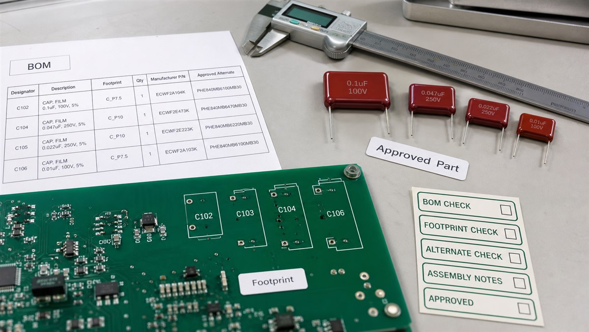
EBest Circuit can help review:
- BOM value consistency
- MFD, uF, nF, and pF value conversion
- capacitor voltage and package information
- approved part number and alternates
- PCB footprint and lead spacing
- polarity or non-polarity notes
- SMT or through-hole assembly method
- tall component clearance
- inspection and packing notes
This support is useful when a project includes legacy BOM formats, mixed capacitor naming, old drawings, customer-supplied components, or replacement parts. Instead of finding the issue after assembly starts, the better path is to catch it during BOM and DFM review.
FAQs About Mylar Capacitor
1. Is a Mylar capacitor the same as a polyester capacitor?
In most practical electronics use, yes. A Mylar capacitor usually refers to a polyester film capacitor.
2. Are Mylar capacitors polarized?
Most Mylar capacitors are not polarized. However, the datasheet should still be checked before assembly.
3. What does 104 mean on a Mylar capacitor?
104 usually means 100,000 pF, which equals 100 nF or 0.1 uF.
4. Can I replace a Mylar capacitor with a ceramic capacitor?
Not always. The capacitance may match, but voltage rating, dielectric behavior, size, footprint, and circuit function must be checked.
5. How should I specify a Mylar capacitor in a BOM?
A good BOM should include capacitance, tolerance, voltage rating, capacitor type, package, lead spacing, manufacturer part number, and approved alternates.
All in all, a mylar capacitor is a small component, but it can still affect sourcing, assembly, testing, and delivery if the specification is incomplete. If your project includes Mylar capacitors, polyester film capacitors, unclear markings, or capacitor replacement risks, please send your Gerber files, BOM, CPL, assembly drawing, and project notes to sales@bestpcbs.com. EBest Circuit can help review the PCB and PCBA manufacturing path before production starts.