

A circuit board capacitor is a passive electronic component mounted on a Printed Circuit Board (PCB) to store and release electrical energy, regulate voltage, filter noise, and stabilize signals in electronic devices. This article explains what a circuit board capacitor is, its working principle, how to identify it, test it, and handle it in PCB assembly—from symbol recognition to replacement and soldering.
Do These Circuit Board Capacitor Problems Sound Familiar?
- Not knowing how to identify a bad capacitor on a circuit board.
- Struggling to test capacitors on a circuit board without damaging components.
- Uncertainty about how to desolder or remove a capacitor from a circuit board safely.
- Confusion over capacitor polarity markings on a circuit board and how they affect installation.
- Hesitation to solder a new capacitor to a circuit board due to fear of poor connections or overheating.
To address these issues, EBest Circuit (Best Technology) provides practical solutions tailored for PCBA production:
- Use visual inspection and ESR meters to find bad capacitors on a circuit board efficiently.
- Apply standard testing procedures to test capacitors on a circuit board without risking damage.
- Follow safe desoldering techniques to remove capacitors from a circuit board cleanly.
- Understand circuit board capacitor polarity markings to ensure correct orientation during installation.
- Leverage professional soldering methods to attach capacitors to a circuit board reliably.
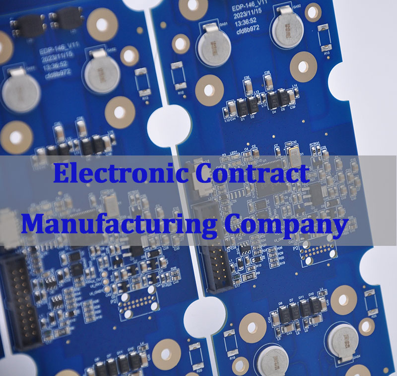
EBest Circuit (Best Technology) is a leading PCBA manufacturer and PCB assembly service provider specializing in high-quality capacitor integration for all types of printed circuit boards. With 20 years of experience in circuit board capacitor replacement, testing, and soldering, we ensure every component meets strict quality standards. For expert guidance or custom PCBA support, pls feel free to contact us at sales@bestpcbs.com.
What Is the Symbol of a Capacitor?
Understanding the symbol for a capacitor is the first step in reading schematics and identifying components on a circuit diagram. The symbol varies slightly depending on the type of capacitor used.
- Standard Non-Polarized Capacitor: Represented by two parallel, vertical lines of equal length separated by a small gap. This indicates a capacitor that can be connected in either direction.
- Polarized Capacitor (Electrolytic): Shown with one straight line (negative plate) and one curved or dashed line (positive plate), often accompanied by a “+” sign near the positive terminal.
- Variable Capacitor: Depicted with an arrow drawn through the parallel lines, indicating that the capacitance value can be adjusted mechanically.
- Location on Diagrams: The capacitor symbol on a circuit board schematic is usually placed between power and ground lines or in series with signal paths to show its filtering or coupling function.
- Importance for Assembly: Recognizing these symbols helps technicians verify the layout before they solder a capacitor to a circuit board, preventing costly errors.
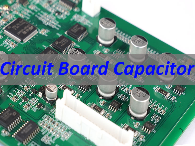
What Does a Capacitor Look Like on a Circuit Board?
Physical appearance helps distinguish different types of capacitors on a circuit board. Their size, shape, and packaging depend on the application and capacitance value.
- Through-Hole Electrolytic Capacitors: Typically cylindrical, tall, and metal-can shaped with a plastic sleeve. They have two leads and are often marked with a stripe indicating the negative pin.
- Ceramic Capacitors: Small, disc-shaped, or rectangular blocks (MLCC). They are usually tan, blue, or brown and lack polarity markings.
- Tantalum Capacitors: Rectangular, often yellow or black, with a clear polarity marking (a stripe or “+”) on one end.
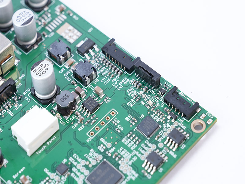
- Surface Mount Device (SMD) Capacitors: Tiny, flat rectangles that sit directly on the PCB surface. They are often unmarked but identified via the PCB silkscreen.
- Identification Tips: To identify a capacitor on a circuit board, look for labels like “C1,” “C2,” etc., near the component. Visual cues like bulging tops or leakage indicate a failed capacitor that needs to be replaced.
What Does a Capacitor Do on a Circuit Board?
A capacitor on a circuit board serves multiple critical functions that ensure the stability and efficiency of an electronic circuit.
- Energy Storage: Acts like a tiny rechargeable battery, storing charge when voltage is applied and releasing it when the main power source drops.
- Filtering (Smoothing): In power supplies, capacitors filter out AC ripple from DC voltage, providing a smooth and stable power line. This is why they are essential in circuit board capacitor replacement for power sections.
- Decoupling and Bypass: Placed close to IC pins to provide a local reservoir of charge, preventing voltage dips when the chip switches states rapidly.
- Signal Coupling: Allows AC signals to pass between stages of a circuit while blocking DC components, which is crucial in audio and RF applications.
- Timing and Oscillation: Works with resistors to create RC timing circuits that control delays, frequencies, and pulse widths.
Why Are Capacitors Used in Circuit Boards?
Capacitors are ubiquitous in electronics because they solve fundamental electrical challenges that resistors and transistors cannot.
- Voltage Stabilization: They prevent voltage spikes and dips, protecting sensitive semiconductors from damage.
- Noise Suppression: By absorbing high-frequency noise, capacitors improve signal integrity and reduce Electromagnetic Interference (EMI).
- Power Management: Essential for managing transient currents in high-speed digital circuits, ensuring the printed circuit board capacitor network supports peak loads.
- Frequency Response Control: Used in filters to allow certain frequencies to pass while blocking others (e.g., in audio crossovers).
- Compact Design: Modern SMD capacitors allow for high-density packing, enabling smaller and more powerful electronic devices.
How to Find a Bad Capacitor on a Circuit Board?
Locating a faulty capacitor on a circuit board requires a systematic approach combining visual checks and electronic measurements.
- Visual Inspection:
- Look for a bulging or domed top (often called “venting”).
- Check for brownish electrolyte leakage around the base.
- Inspect for discoloration or burnt marks on the PCB near the component.
- ESR (Equivalent Series Resistance) Testing:
- Use an ESR meter to check the internal resistance. A high ESR indicates a failing capacitor even if capacitance looks normal.
- Capacitance Measurement:
- Use a multimeter set to capacitance mode. Compare the reading to the value printed on the capacitor; a significant deviation suggests failure.
- In-Circuit Testing:
- While you can test a capacitor on a circuit board, remember that parallel components can affect readings. Desoldering one leg may be necessary for an accurate measurement.
- Thermal Imaging:
- Overheating capacitors will appear brighter/hotter than surrounding components under a thermal camera.
How to Test a Capacitor on a Circuit Board?
Testing capacitors on a circuit board ensures reliability before final assembly or during troubleshooting.
- Safety First: Always discharge the capacitor using a resistor before touching it. High-voltage capacitors can hold a lethal charge.
- Using a Digital Multimeter (DMM):
- Set the dial to the capacitance (µF or nF) setting.
- Connect the probes to the leads. Ensure correct polarity for polarized caps.
- Read the value and compare it to the rated value (usually ±20% tolerance is acceptable).
- Using an ESR Meter:
- This tool measures resistance without needing to fully discharge the cap (in many cases).
- Low ESR is good; high ESR means the capacitor is drying out and failing.
- Using an Oscilloscope:
- Observe the charge/discharge curve. A slow rise time or inability to hold charge indicates a problem.
- Can You Test a Capacitor on a Circuit Board?
- Yes, but be aware of parallel paths. If readings are inconsistent, lift one leg of the capacitor to isolate it from the circuit.
Can You Bypass a Capacitor on a Circuit Board?
Bypassing a capacitor is a diagnostic technique, but it comes with significant caveats.
- Temporary Diagnostic Tool: If you suspect a capacitor is causing a short or blocking a signal, temporarily connecting a wire around it (bypassing) can help determine if the capacitor is the culprit.
- Risks Involved:
- Voltage Spikes: Removing a decoupling capacitor can cause voltage spikes that destroy ICs.
- Signal Distortion: Bypassing a filter capacitor will introduce noise and hum into audio or data signals.
- When to Do It: Only perform this on low-voltage, non-critical circuits and never as a permanent fix.
- Alternative: Instead of bypassing, consider replacing the capacitor on the circuit board with a known good one.
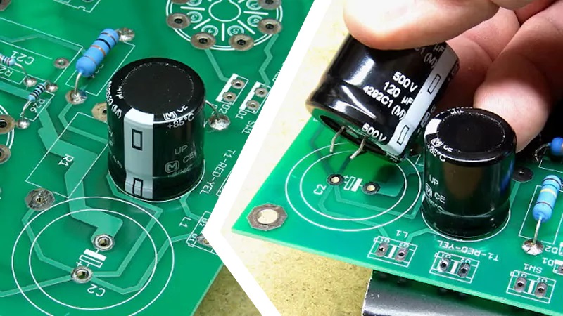
How to Install a Capacitor on a Circuit Board?
Proper installation ensures the capacitor performs its function correctly and lasts the lifetime of the device.
- Identify Polarity: Check the circuit board capacitor polarity markings. Electrolytic and tantalum capacitors must be installed in the correct orientation. The stripe on the board usually indicates the negative side or ground.
- Lead Forming: For through-hole parts, bend the leads to match the hole spacing on the PCB.
- Insertion: Push the capacitor leads through the holes until the body sits flush with the board.
- Secure the Component: Bend the leads slightly outward on the backside to hold the capacitor in place during soldering.
- Verify Placement: Double-check the value and polarity before applying heat. Installing a capacitor backwards can cause it to explode.
How to Solder a Capacitor to a Circuit Board?
Soldering a capacitor to a circuit board requires precision to avoid heat damage and ensure a solid electrical connection.
- Preparation:
- Clean the pads on the PCB and the leads of the capacitor.
- Apply a small amount of flux to the pads to improve solder flow.
- Heat Control:
- Use a soldering iron set to 350°C–370°C (660°F–700°F).
- Touch the pad and the lead simultaneously with the iron tip for 2–3 seconds.
- Applying Solder:
- Feed solder into the joint (not directly onto the iron). The solder should melt and flow smoothly around the lead and pad.
- Inspection:
- A good solder joint is shiny, smooth, and concave. A dull or lumpy joint indicates a “cold joint” and must be reflowed.
- Trimming Leads: After soldering, clip the excess lead length close to the board to prevent short circuits.
- Surface Mount (SMD) Technique: Use tweezers to hold the capacitor in place, solder one pad first, then adjust alignment before soldering the second pad.
In conclusion, a circuit board capacitor is a fundamental component that stores energy, filters signals, and stabilizes voltages in electronic systems. From understanding the capacitor symbol on a circuit board to mastering how to test, install, or replace capacitors on a circuit board, this guide equips you with actionable insights for working with PCBs effectively. EBest Circuit (Best Technology) stands ready to support your PCBA needs with expertise in circuit board capacitor integration and testing. Pls feel free to contact us anytime at sales@bestpcbs.com to learn more about our services.
FAQs About Circuit Board Capacitor
1. What is the function of a capacitor on a circuit board?
The primary function of a capacitor is to store and release electrical energy within a circuit. On a printed circuit board (PCB), capacitors act as local energy reservoirs that stabilize voltage levels and filter out electronic noise. They ensure that sensitive components receive a steady power supply by “smoothing” out fluctuations and blocking direct current (DC) while allowing alternating current (AC) to pass through.
2. How can you tell if a capacitor is bad on a PCB?
You can identify a failing capacitor through both visual inspection and electrical testing:
- Visual Signs: Look for bulging or leaking at the top (vent), brownish electrolyte residue, or “doming” on electrolytic capacitors.
- Physical Damage: Any signs of charring or a “burnt” smell near the component.
- Multimeter Testing: Using the capacitance setting ($C$) on a digital multimeter, you can measure the component to see if its actual value matches the rated capacitance printed on its casing.
3. What are the different types of capacitors used in PCB assembly?
Capacitors are categorized by their dielectric material and construction, which determines their stability and application:
- Ceramic Capacitors: The most common type, used for high-frequency applications and bypass filtering due to their small size and low cost.
- Electrolytic Capacitors: Polarized components with high capacitance values, typically used for power supply smoothing and bulk energy storage.
- Tantalum Capacitors: Known for high volumetric efficiency and stability, often used in space-constrained or high-reliability devices.
- Film Capacitors: Frequently used in power circuits and audio applications where high precision and low leakage are required.
4. Why do capacitors fail on printed circuit boards?
Capacitor failure is often attributed to heat, voltage stress, or age.
- Thermal Stress: Excessive heat causes the liquid electrolyte in electrolytic capacitors to evaporate over time, leading to a loss of capacitance.
- Overvoltage: Subjecting a capacitor to a voltage higher than its rated limit can cause a dielectric breakdown or a short circuit.
- ESR Increase: As capacitors age, their Equivalent Series Resistance (ESR) increases, which generates more internal heat and eventually leads to total component failure.
You may also like


Tags: Circuit Board Capacitor, symbol for capacitor, what is the symbol for capacitor