





PCB standoffs hold a circuit board at a controlled distance from an enclosure, mounting plate, or second PCB. Although they are simple mechanical parts, the wrong standoff can cause board flexing, damaged solder joints, electrical shorts, connector misalignment, or difficult assembly.
Choosing the correct part involves more than matching an M2 or M3 screw. Engineers also need to consider the required board clearance, underside component height, mechanical load, electrical isolation, grounding, operating temperature, vibration, and access for installation.
This guide explains the main types of PCB standoffs, common materials, practical hole and thread sizes, mounting methods, and the information buyers should prepare before requesting a quotation.
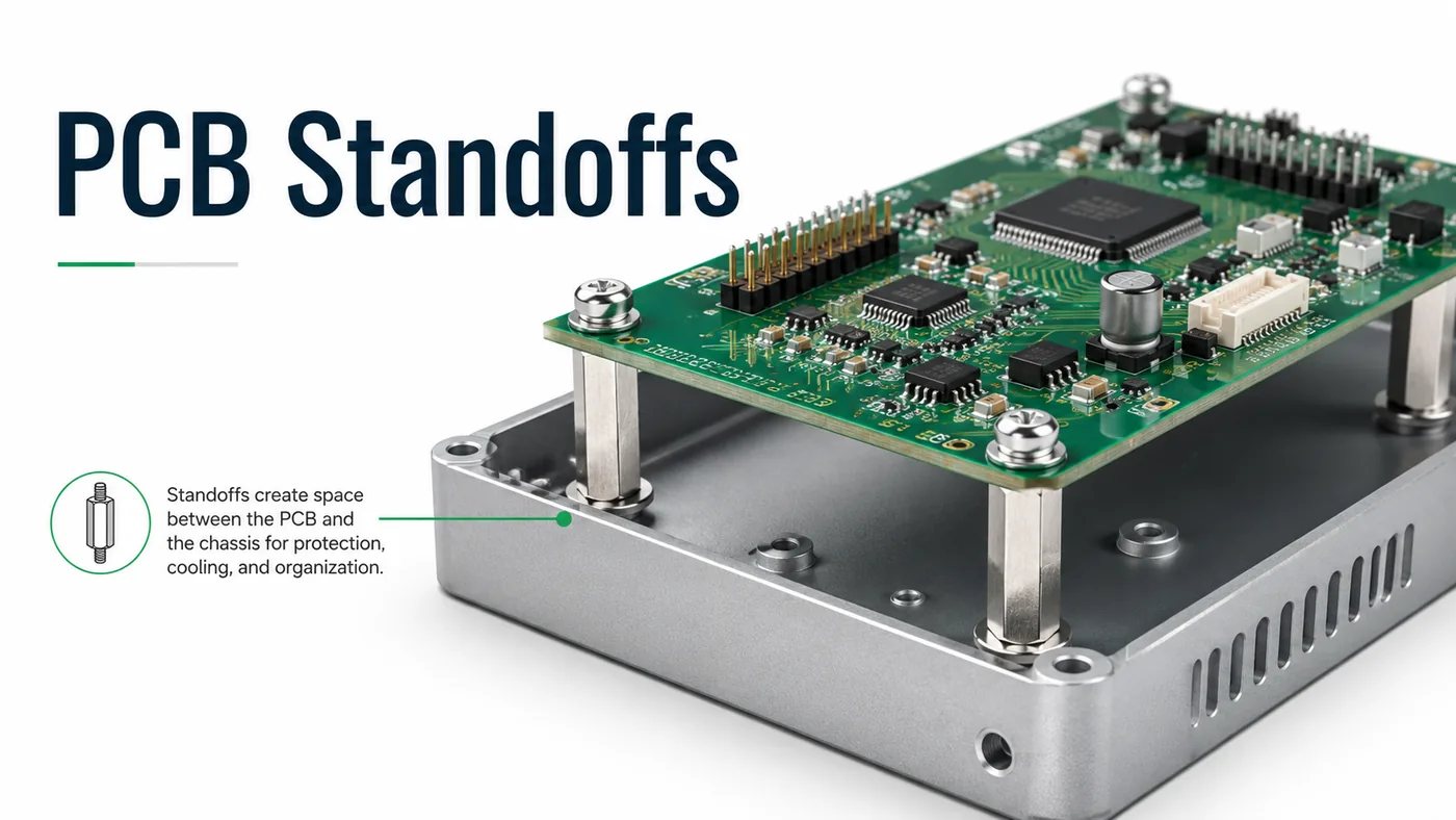
What Are PCB Standoffs and Why Are They Used?
PCB standoffs are mechanical supports that maintain a fixed gap between a printed circuit board and another surface. Most designs use internal threads, external threads, snap features, adhesive bases, or press-fit bodies to secure the PCB.
Their primary purpose is to prevent the board from resting directly on an enclosure. The underside of a PCB may contain solder joints, component leads, test pads, vias, and exposed copper. Without sufficient clearance, these features can touch a conductive surface or become damaged during assembly.
Standoffs also control mechanical stress. Cable insertion, terminal-block tightening, switch operation, and repeated servicing can bend a PCB if the nearest support point is too far away. Correct placement transfers those forces into the enclosure instead of through the laminate and solder joints.
Common functions include:
- Maintaining clearance beneath the PCB
- Supporting heavy components and connectors
- Reducing board flex during assembly and use
- Creating airflow around heat-producing components
- Aligning connectors with enclosure openings
- Separating stacked circuit boards
- Providing electrical insulation
- Creating an intentional chassis-ground connection
PCB standoff height should be based on the tallest feature beneath the board, not only the nominal PCB thickness. Through-hole leads, solder fillets, connector latches, test pins, and wire loops may extend below the laminate.
For example, a 3 mm standoff is usually too short when the tallest underside feature is already 2.5 mm. The remaining 0.5 mm does not account for solder variation, PCB bow, enclosure tolerance, contamination, or movement under vibration. A 5 mm or 6 mm part may provide a more practical margin.
Board size and thickness matter as well. A compact 1.6 mm FR-4 board may only need 4 mounting points. A larger or thinner PCB may require central supports, especially near transformers, heatsinks, terminal blocks, and frequently used connectors.
PCB Standoffs vs. Spacers: What Is the Difference?
The main difference is the fastening method. A PCB standoff normally includes an internal thread, external thread, or both. A spacer is usually an unthreaded sleeve through which a separate screw or bolt passes.
| Feature | PCB Standoff | PCB Spacer |
|---|---|---|
| Threaded feature | Usually included | Usually absent |
| Fastening method | Screw connects directly to the standoff | Screw passes through the spacer |
| Typical loose parts | Fewer | Often requires a screw and nut |
| Assembly access | May require access from only 1 side | Often requires access from both sides |
| Board stacking | Well suited | Possible with a long through-bolt |
| Serviceability | Usually easier | Depends on nut accessibility |
| Typical use | Repeatable PCB mounting | Basic distance control |
A spacer is suitable when a screw can pass through the enclosure, spacer, PCB, and retaining nut. This arrangement is simple and economical, but it may be inconvenient when the nut becomes inaccessible after final assembly.
A threaded standoff is generally better for products that must be opened, repaired, or assembled in stages. It can remain attached to the enclosure while the PCB is removed.
Some suppliers use “PCB standoff spacers” as a broad product term. Always check the drawing rather than relying on the name. Confirm whether the part has a threaded hole, external stud, plain bore, snap lock, or adhesive base.
What Types of PCB Standoffs Are Available?
PCB mounting standoffs are available in several configurations. The correct type depends on the enclosure design, assembly sequence, available tool access, and whether the board will be removed during maintenance.
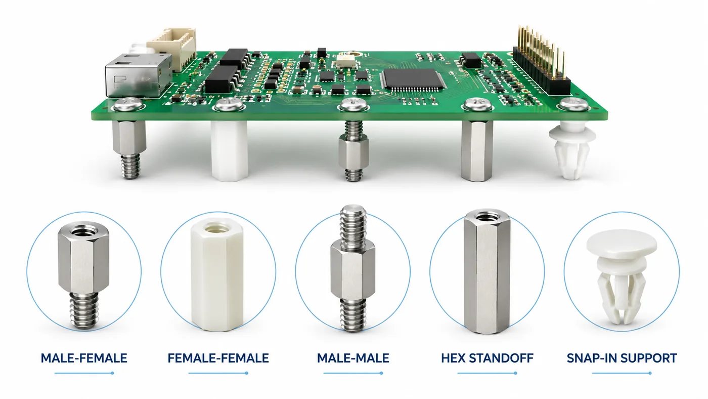
Male-Female PCB Standoffs
A male-female standoff has an external threaded stud on 1 end and an internally threaded hole on the other. This configuration is widely used because the male end can screw into an enclosure, threaded insert, or another standoff, while the female end accepts the PCB mounting screw.
It is particularly useful for:
- Stacked PCBs
- Threaded enclosure bosses
- Modular assemblies
- Boards that must be removed from above
- Structures requiring several standoffs in series
Check the male thread length separately from the standoff body height. Body height controls the board spacing. Thread length determines whether the part can fully engage without bottoming out or protruding into another component.
Female-Female PCB Standoffs
Female-female standoffs have internal threads at both ends. A lower screw attaches the standoff to the enclosure, while an upper screw secures the PCB.
They offer flexibility because different screw lengths can be used on each side. However, the lower fastener must remain accessible during assembly. They are less convenient when the underside becomes enclosed before the PCB is installed.
Male-Male PCB Standoffs
Male-male standoffs have external studs at both ends. They are mainly used between 2 threaded parts rather than directly through a standard PCB mounting hole.
Typical applications include:
- Threaded mounting plates
- Modules with threaded inserts
- Mechanical support frames
- Equipment with captive nuts
When used with a plain PCB hole, a separate nut or threaded insert is required.
Hex and Round PCB Standoffs
Hex PCB standoffs can be held with a wrench or nut driver. This makes them easier to install, remove, and tighten to a controlled torque.
Round standoffs have a smaller visual profile and may fit into narrow spaces. However, a smooth round body can rotate unless it includes a knurled area, slot, shoulder, or press-fit feature.
Hex bodies are generally the more practical option for repeatable manual assembly. Round bodies are useful when diameter, appearance, or clearance around nearby components is the priority.
Snap-In and Push-Fit Supports
Snap-in supports use flexible locking features instead of screws. They can reduce assembly time and hardware count in high-volume products.
They work best when:
- The PCB is lightweight
- Mechanical load is moderate
- The board will rarely be removed
- Electrical isolation is required
- Fast assembly is more important than high clamping force
Their performance depends heavily on hole diameter, panel thickness, PCB thickness, and plastic grade. Repeated removal may weaken the locking feature.
Adhesive PCB Standoffs
Adhesive standoffs attach directly to an enclosure without drilled holes. They are convenient for prototypes, retrofit projects, and enclosures whose external surfaces must remain unmarked.
The adhesive bond is only as reliable as the mounting surface. Oil, dust, powder coating, textured plastic, humidity, and elevated temperature can reduce adhesion.
Adhesive mounting is normally unsuitable for heavy boards, high-vibration products, safety-critical equipment, or assemblies where detachment could cause a short circuit.
Self-Clinching Standoffs
Self-clinching standoffs are pressed into sheet metal. During installation, the panel material flows into the retaining features and locks the fastener in place.
They provide a strong, permanent threaded mounting point but require:
- Compatible sheet material
- A specified panel thickness
- A closely controlled mounting hole
- Adequate edge distance
- Installation with a press
Hammer installation is not recommended because it can distort the panel and prevent proper material flow around the fastener.
Stackable PCB Standoffs
Stackable standoffs are used when 2 or more circuit boards must be mounted vertically.
The selected height must accommodate more than component bodies. Engineers should also check:
- Connector mating height
- Solder-joint projection
- Cable bend radius
- Airflow between boards
- Test-point access
- Screw-head and washer thickness
- PCB thickness tolerance
- Cumulative standoff tolerances
A nominal 10 mm standoff does not always provide 10 mm of usable component clearance. The complete mechanical stack must be reviewed.
Nylon, Brass, Aluminum, or Stainless Steel: Which Material Should You Choose?
Material selection usually depends on electrical behavior, mechanical load, weight, temperature, and environmental exposure.
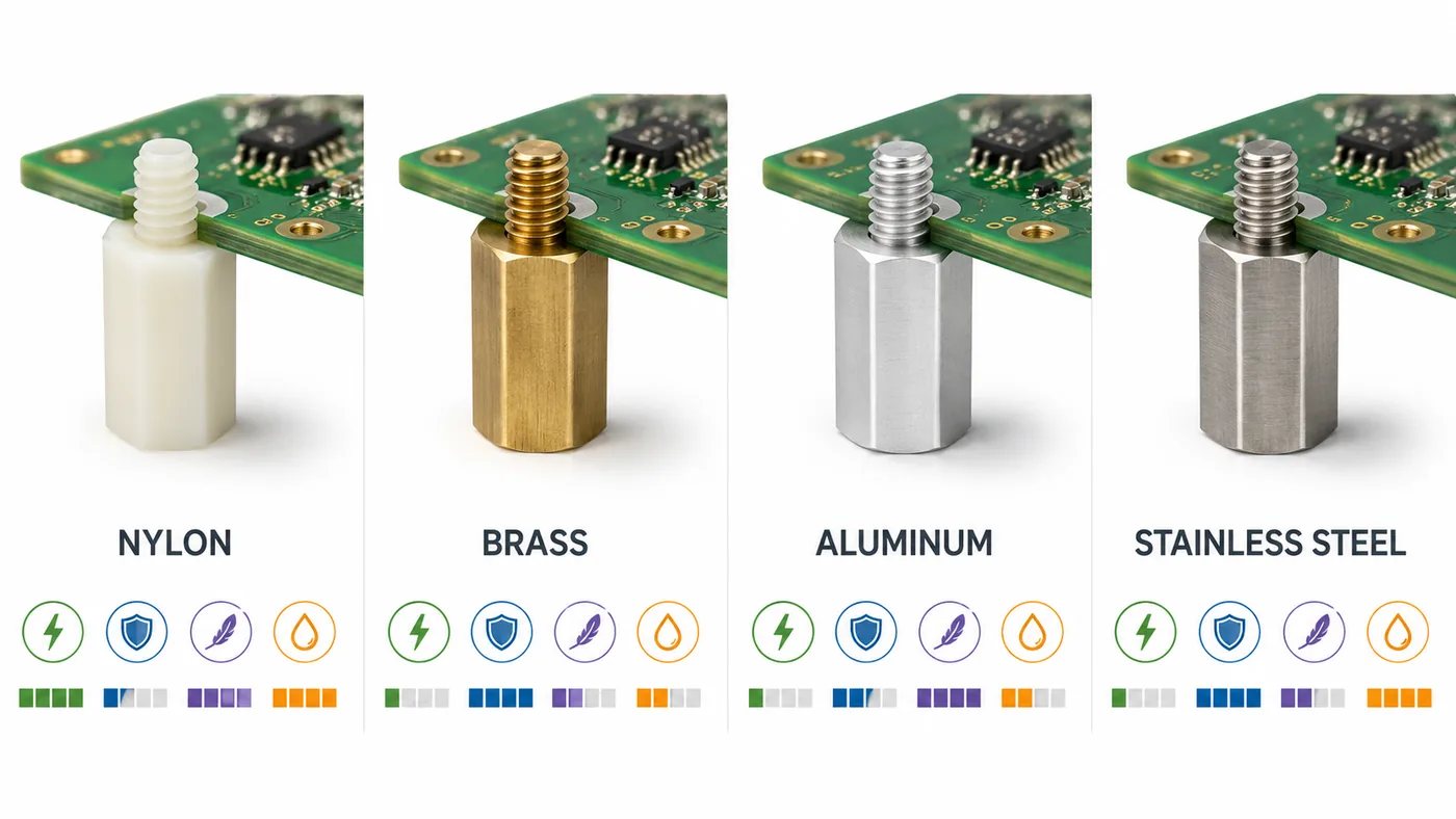
| Material | Electrical Behavior | Mechanical Characteristics | Weight | Typical Application |
|---|---|---|---|---|
| Nylon | Insulating | Suitable for light and moderate loads; threads can strip | Very low | Consumer electronics, prototypes, low-voltage boards |
| Brass | Conductive | Stable dimensions and durable threads | Relatively high | Industrial controls, metal enclosures |
| Aluminum | Conductive unless insulated by finish | Good strength-to-weight ratio | Low | Portable devices, aerospace, drones |
| Stainless steel | Conductive | High strength and wear resistance | High | Outdoor, transportation, high-vibration equipment |
| Engineering plastic | Insulating | Depends on polymer grade | Low | Medical, high-voltage, high-temperature applications |
Nylon PCB standoffs are a practical choice when insulation, low weight, and moderate cost are more important than high clamping force. They are common in low-voltage electronics and lightweight enclosures.
However, “nylon” does not define a complete specification. Moisture absorption, heat resistance, flame rating, and mechanical strength vary by grade. General-purpose nylon may soften or creep near power resistors, transformers, high-current terminals, or hot metal panels.
Brass standoffs provide strong, repeatable threads and good dimensional stability. Nickel-plated brass is widely used in industrial products because it offers reliable machining, corrosion resistance, conductivity, and a durable surface.
Aluminum is appropriate when weight reduction matters. It is often selected for portable devices, drones, vehicles, and aerospace equipment. Designers should still evaluate thread wear, surface treatment, and galvanic interaction with other metals.
Stainless steel is preferred when high strength, corrosion resistance, and vibration durability are required. It may be unnecessary for stationary indoor equipment where brass or aluminum already provides sufficient performance.
Metal standoffs can create an electrical path between the PCB and chassis. That path should be intentional. If the mounting point is used for chassis grounding, define the copper pad, plated hole, washer, surface finish, and contact pressure. Avoid allowing exposed signal copper to approach the full metal envelope of the screw, washer, and standoff.
For high-voltage assemblies, the required creepage and clearance must be calculated separately. An insulating plastic standoff does not correct inadequate spacing between conductive PCB features and the enclosure.
PCB Standoff Size Chart: Threads, Hole Sizes, Heights, and Clearance
The PCB standoff hole size must be larger than the screw diameter. It also needs to accommodate fabrication tolerance, plating, hole position, enclosure alignment, and installation angle.
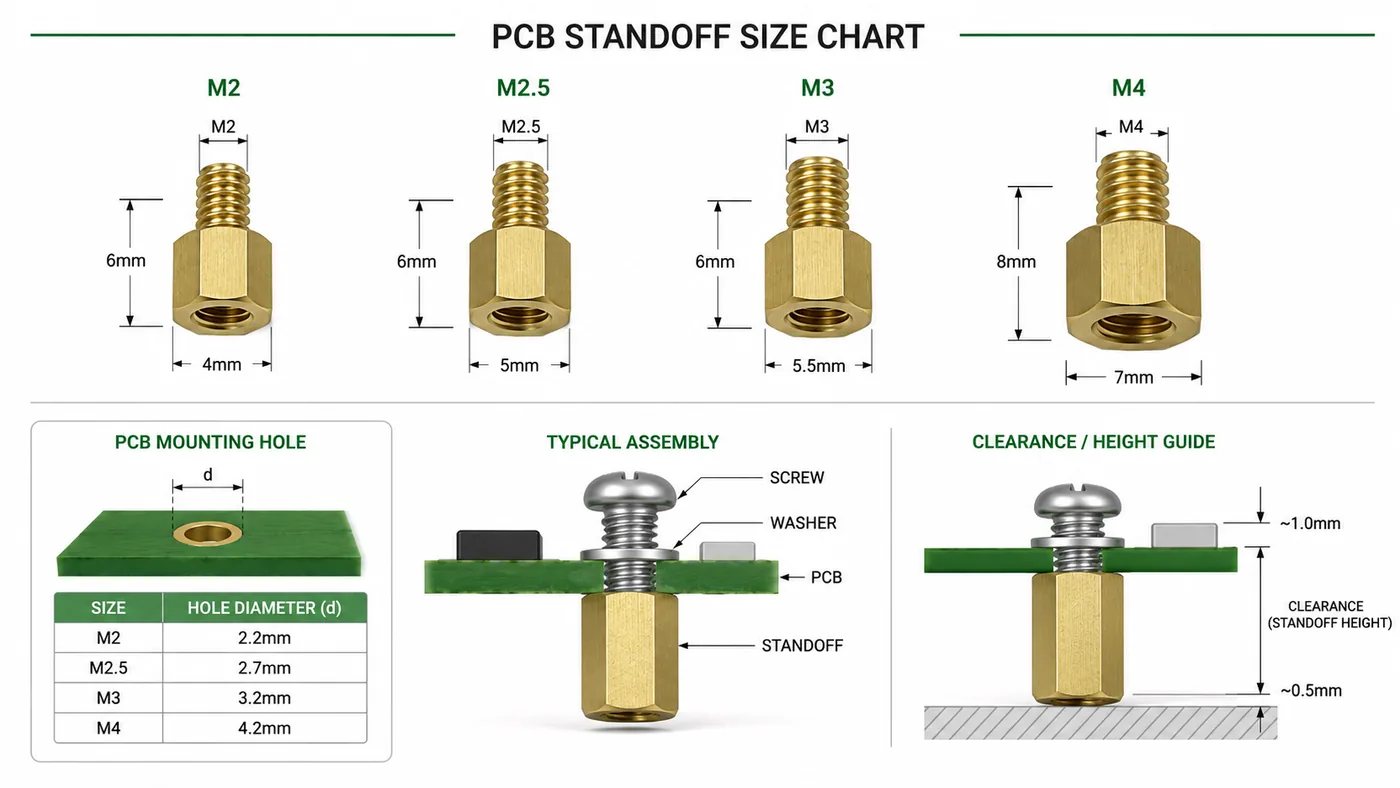
The following PCB standoff sizes are useful starting points rather than universal limits.
| Thread Size | Screw Diameter | Typical Finished PCB Hole | Common Body Heights | Typical Use |
|---|---|---|---|---|
| M2 | 2.0 mm | 2.2–2.4 mm | 3–15 mm | Sensors, compact modules |
| M2.5 | 2.5 mm | 2.7–2.9 mm | 4–20 mm | Embedded controllers, communication modules |
| M3 | 3.0 mm | 3.2–3.5 mm | 5–25 mm | Industrial controls, power boards |
| M4 | 4.0 mm | 4.3–4.6 mm | 6–30 mm | Large or heavy PCBs |
| 4-40 UNC | About 2.85 mm | About 3.0–3.3 mm | 1/4–1 in | North American electronic equipment |
| 6-32 UNC | About 3.51 mm | About 3.7–3.9 mm | 1/4–1 in | Enclosures and heavier assemblies |
Use a tighter hole only when PCB and enclosure positions are well controlled. Larger boards mounted at several points may need additional clearance to absorb positional variation between the PCB and sheet-metal parts.
The screw head and washer must still overlap the laminate sufficiently. Enlarging the hole without checking the bearing area can concentrate pressure and damage the PCB.
Choosing Standoff Height
The tolerance allowance may include:
- PCB bow and twist
- Component-height tolerance
- Solder projection
- Enclosure flatness
- Standoff length tolerance
- Washer thickness
- Conformal coating
- Movement during vibration
For an ordinary low-voltage product, an additional 1–2 mm may be sufficient after the tallest underside feature. Safety-regulated, contaminated, high-voltage, or high-vibration equipment may require a larger engineered margin.
Checking Thread Engagement
The screw should engage enough thread to resist loosening and stripping, but it must not bottom out before clamping the PCB.
The correct screw length depends on:
- PCB thickness
- Washer thickness
- Standoff thread depth
- Thread lead-in
- Enclosure thickness
- Required engagement length
A screw that bottoms out may feel tight even though the PCB remains loose.
Avoiding Metric and Imperial Mix-Ups
M3 and 4-40 threads appear similar but are not interchangeable. A mismatched screw may begin to engage and then bind, damaging both parts.
The BOM and assembly drawing should identify the complete thread designation. Descriptions such as “small standoff” or “3 mm screw” are not sufficient for controlled production.
How Do You Choose the Right PCB Standoffs?
A reliable selection process begins with the complete assembly rather than a catalog filter.
Confirm the Finished Mounting-Hole Diameter
Check whether the mounting hole is plated or non-plated. Plated holes become smaller after copper deposition. Non-plated holes normally remain closer to the mechanical drill size and are often preferred for isolated mounting.
Plated holes are appropriate when the mounting point intentionally connects to ground or requires a reinforced copper structure.
Calculate the Required Clearance
Measure every feature below the PCB, including component bodies, solder fillets, test points, connector clips, wire loops, and heatsink hardware.
Also consider whether the enclosure can bend toward the PCB under installation pressure, impact, or external mounting loads.
Decide Whether the Mount Should Insulate or Conduct
Use nylon or another insulating material when the board must remain electrically isolated from the enclosure.
Use metal standoffs when higher strength, durable threads, or a deliberate chassis connection is needed. Do not assume a metal part will provide a reliable ground through paint, anodizing, oxidation, or loose contact surfaces.
Evaluate Mechanical Load
A small sensor board can usually use nylon supports. A larger board containing transformers, relays, heatsinks, or large terminal blocks may require metal standoffs and more mounting points.
Operational forces are equally important. A lightweight board can still experience high local stress when users insert cables or tighten field wiring.
Review the Operating Environment
Check the expected:
- Continuous and peak temperature
- Humidity and condensation
- Shock and vibration
- Chemical exposure
- Salt spray
- UV exposure
- Cleaning process
- Flammability requirement
- Sterilization process
For regulated or long-life products, request the actual material grade and finish rather than accepting a generic description such as “plastic” or “metal.”
Match the Thread Configuration to the Assembly Sequence
Male-female standoffs are useful when the part screws into the enclosure and the PCB is installed from above.
Female-female parts work when both sides remain accessible. Snap-in supports suit fast assembly but are less convenient for repeated servicing.
The selected configuration should allow installation and removal without dismantling unrelated modules.
Check Tool Access
Confirm that a screwdriver, socket, or wrench can reach the fastener without hitting a connector, capacitor, enclosure wall, heatsink, or cable.
This issue is often missed because the mounting hole is visible in the PCB layout but inaccessible in the assembled 3D model.
Decide Whether a Custom Part Is Necessary
Standard PCB standoffs are preferable when they meet the mechanical requirements. They are easier to source, replace, and qualify.
Custom PCB standoffs may be justified when the assembly requires:
- A nonstandard body height
- Different threads on each end
- A special thread length
- Tight length tolerance
- A shoulder or locating diameter
- Anti-rotation features
- Special material or plating
- Automated insertion features
For quotation, provide a dimensioned drawing with thread sizes, body shape, height, stud length, material, finish, tolerances, quantity, and operating environment.
For a PCB or PCBA project, EBest Circuit can review mounting holes, copper keepouts, enclosure interfaces, and assembly drawings during engineering communication. Gerber files, drill data, BOM, mechanical drawings, and the proposed standoff specification should be submitted together where possible.
How Should PCB Standoffs Be Placed and Installed?
Standoff placement should follow the actual mechanical loads on the PCB.
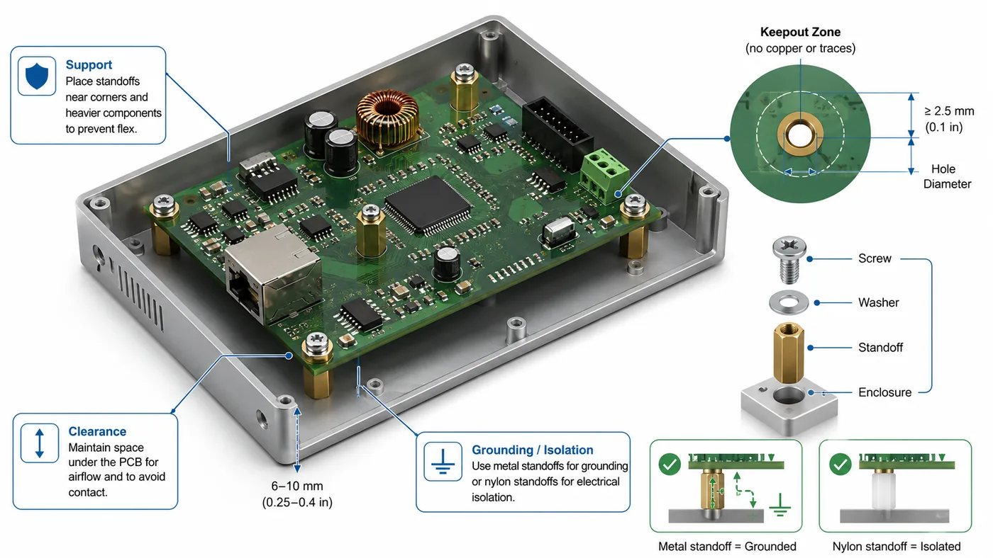
Corner supports control overall movement, but they may not protect areas exposed to concentrated force. Additional supports are often needed near:
- Board-edge connectors
- USB, HDMI, Ethernet, and power connectors
- Screw terminals
- Push buttons and switches
- Card sockets
- Transformers
- Large inductors
- Heatsinks
- Battery holders
- Mezzanine connectors
A large PCB mounted only at 4 corners can flex significantly at the center. Board dimensions, thickness, component weight, copper distribution, and connector forces should determine whether intermediate supports are required.
Define a Realistic Keepout Area
The keepout should account for the complete hardware envelope, not only the drill diameter.
Include:
- Screw-head diameter
- Washer diameter
- Standoff body or hex width
- Tool clearance
- Hole-position tolerance
- Possible rotation
- Nearby copper
- Component-body clearance
A trace may be clear of the nominal hole but still lie beneath a washer or metal standoff body.
Separate Grounded and Isolated Mounting Points
An isolated mounting hole normally uses a non-plated hole with copper pulled back around it.
A grounded mounting hole may use plating and copper connected to chassis ground. The contact area, surface finish, washer arrangement, and grounding purpose should be defined in the design.
Do not connect every mounting hole to digital ground by default. Multiple chassis connections can create unintended current paths or complicate EMC behavior.
Control Tightening Torque
Overtightening can:
- Crack FR-4 around the hole
- Strip nylon threads
- Deform aluminum threads
- Bow the PCB
- Damage nearby ceramic components
- Compress insulating washers
- Distort thin sheet metal
Washers distribute pressure but do not replace torque control. Production instructions should specify the screw, washer, tightening method, and torque when reliability is important.
Prevent Loosening Where Necessary
Vibration-resistant products may use lock washers, prevailing-torque nuts, thread-locking compounds, or other retention methods.
The chosen solution must suit the standoff material and service requirements. Strong threadlocker may make a small brass or aluminum standoff difficult to remove, while some chemical products can damage plastics.
Review the Full Assembly Sequence
Confirm whether each fastener remains accessible after cables, heatsinks, batteries, displays, or upper PCBs are installed.
A serviceable design should allow the PCB to be removed without dismantling unrelated parts of the product.
Can 3D-Printed PCB Standoffs Be Used in Production?
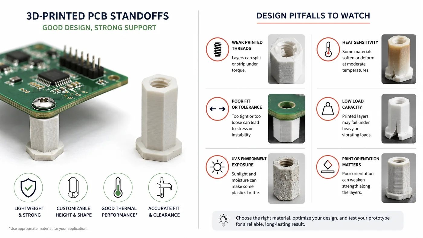
3D-printed PCB standoffs are useful for prototypes, enclosure trials, alignment checks, and temporary fixtures. They allow engineers to verify board height and hole position before ordering machined or molded parts.
Their suitability for final production depends on the material, printing process, orientation, temperature, load, and required service life.
| Material | Main Advantage | Main Limitation | Practical Use |
|---|---|---|---|
| PLA | Easy to print and dimensionally stable | Limited heat and creep resistance | Room-temperature prototypes |
| PETG | Tougher and more heat resistant than PLA | Can deform under continuous load | Functional prototypes |
| ABS or ASA | Better heat and impact performance | Requires more process control | Environmental and enclosure trials |
| Printed nylon | Tough and fatigue resistant | Absorbs moisture and may vary dimensionally | Clips and functional supports |
| High-performance polymer | Better heat and chemical resistance | High material and equipment cost | Specialized low-volume production |
Small printed threads are often unreliable. M2 and M2.5 internal threads may wear quickly or vary between prints. Heat-set inserts, captive nuts, and through-bolts usually provide better durability.
Print orientation also affects strength. A standoff loaded across layer boundaries may split even when the same geometry performs well in another orientation.
Before using a printed standoff in production, evaluate:
- Creep under screw preload
- Operating temperature
- Shock and vibration
- Moisture absorption
- Flammability
- Chemical exposure
- Electrical insulation
- Thread durability
- Dimensional repeatability
- Regulatory requirements
3D printing is well suited to prototypes and customized low-volume fixtures. Injection-molded nylon and machined metal parts are generally more consistent for repeated servicing, sustained loads, high-volume assembly, and certified equipment.
What PCB Standoff Mistakes Cause Assembly Problems?
Most problems result from incomplete coordination between the PCB, enclosure, and hardware drawings.
Using the Thread Diameter as the Hole Diameter
An M3 screw should not use a 3.0 mm finished clearance hole. Additional clearance is required for fabrication and assembly tolerance.
Ignoring Underside Features
Solder joints, through-hole leads, test points, and connector clips can extend below the PCB. Clearance must be measured from the lowest physical feature.
Supporting Only the Corners
Large boards may flex near heavy components and connectors even when all 4 corners are fixed. Add support where loads are applied.
Placing Metal Hardware Too Close to Copper
The washer and standoff body are wider than the screw. Copper clearances must reflect the complete mechanical envelope.
Overtightening Nylon Threads
Nylon threads can strip before the installer feels a strong increase in torque. Use controlled tightening and appropriate thread engagement.
Mixing Metric and Imperial Parts
M3 and 4-40 hardware can easily be confused. Use precise BOM descriptions, separate storage, and thread gauges where necessary.
Allowing the Screw to Bottom Out
A bottomed screw may appear tight without clamping the PCB. Check the available thread depth before specifying screw length.
Ignoring Tolerance Accumulation
Stacked boards can become misaligned when small variations in PCB thickness, standoff height, connector position, and enclosure dimensions accumulate.
Using Adhesive Supports Without Testing the Surface
An adhesive that bonds well to clean aluminum may fail on powder coating, oily steel, or low-surface-energy plastic. Validate the actual production surface.
Forgetting Tool Clearance
A fastener may be impossible to reach once tall components or enclosure walls surround it. Review the assembled model, not only the 2D PCB layout.
FAQ
1. What size standoff should I use for a PCB?
M2 and M2.5 standoffs are common for compact modules. M3 is widely used for industrial and general-purpose boards. M4 may be appropriate for larger or heavier assemblies.
Choose the height from the tallest underside feature, then add enough clearance for tolerances, board movement, and electrical separation.
2. What PCB hole size is needed for M2, M2.5, and M3 standoffs?
Typical starting values are:
- M2: 2.2–2.4 mm
- M2.5: 2.7–2.9 mm
- M3: 3.2–3.5 mm
The final finished-hole size should reflect plating, enclosure alignment, washer size, fastener drawings, and the PCB manufacturer’s tolerance.
3. Are nylon PCB standoffs better than metal standoffs?
Nylon is better when insulation, low weight, and moderate cost are the main priorities. Metal is more suitable when the assembly needs durable threads, higher strength, vibration resistance, or a defined chassis-ground path.
4. How many standoffs does a PCB need?
A small, lightweight PCB may only need 4 corner supports. Larger boards often require additional mounting points near heavy components, connectors, switches, and long unsupported spans.
Placement is more important than simply increasing the quantity.
5. Can metal PCB standoffs connect the board ground to the chassis?
Yes, but the connection must be designed intentionally. Use a suitable plated mounting hole or conductive pad, controlled hardware, compatible surface finishes, and reliable contact pressure.
Paint, anodizing, oxidation, contamination, and loose fasteners can make an assumed ground connection unreliable.
How Can EBest Circuit Support Your PCB and PCBA Assembly?
PCB standoffs should be selected as part of the full mechanical and electrical assembly. Confirm the thread, finished hole size, board clearance, material, support position, grounding requirement, environment, and assembly sequence before ordering.
For a PCB or PCBA quotation, provide the Gerber files, drill data, BOM, assembly drawing, mechanical dimensions, expected quantity, and enclosure or mounting requirements. EBest Circuit can review these details during project evaluation and help identify potential fabrication or assembly conflicts before production. Contact sales@bestpcbs.com to discuss your project.







