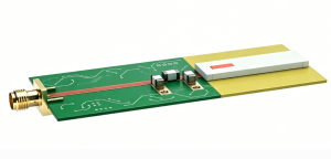
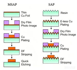
A PCB copper coin push-out test measures the force needed to move a copper insert out of its board cavity under a defined fixture and loading direction. Use it to compare mechanical retention on representative specimens. A high force on its own does not demonstrate reliable heat transfer, good solder contact, or retention after reflow.
Before accepting a report, check whether it names the board and coin revision, identifies the push direction, and states the acceptance criterion and thermal condition. For example, a room-temperature result on an unassembled coupon cannot substitute for post-reflow data when the approved inspection plan requires it.
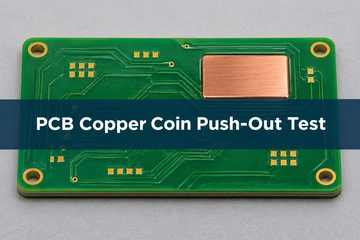
Copper Coin PCB Process
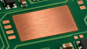
A copper coin is a solid insert that provides a local heat path through a PCB. A retention test checks the way the insert is held, not the conductivity of the copper. Verify the construction before comparing results: a press-fitted coin and a bonded coin can carry the same load through different interfaces, and either can be sensitive to changes in support, geometry or conditioning.
| Construction or check | What a result can tell you | When to use it |
| Press-fitted coin: push-out | Resistance to displacement in the chosen direction. Inspect the cavity wall after loading. | Compare matching fit geometry before and after agreed assembly exposure. |
| Bonded coin: push-out | Response of the joint, insert and surrounding board together. Inspect the exposed failure surfaces. | Compare representative bonded specimens with matched cure, support and temperature. |
| Either construction: surface-height inspection | Step at the exposed coin face relative to the drawing datum. Does not establish retention. | Check coplanarity or package seating; keep this result separate from force. |
Choose the check from the suspected failure. An insert that moves under load calls for retention evidence. A fixed insert that sits below the assembly datum calls for a surface-height check. A fixed, flush insert that still runs hot calls for evidence from the thermal path, including the interfaces to the package and heat sink.
Press Fit Retention Force
Insertion force is the load recorded while seating the coin; retention force is the load observed when a separate test tries to move it out. The insertion trace can flag process changes, but it does not replace a push-out test. A high seating load could reflect useful interference, a burr or poor alignment. Use the released drawing and inspection plan to decide what the load means.
Record geometry that can change retention: insert width and thickness in mm, cavity dimensions, locating features, board thickness and whether a shoulder prevents movement in one direction. When comparing press-fitted and bonded alternatives, use the force trace together with post-test inspection. Do not pick a construction based on force alone if it fails package seating or the required thermal performance.
Push Out Test Procedure
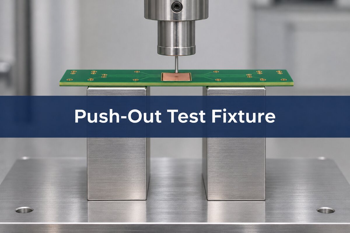
Support the PCB around the test feature without blocking the insert, and load the insert in the defined direction with a centered contact. The lab should approve a fixture drawing and the test settings before treating any result as comparable. Treat the specimen as destructive: it cannot return to a deliverable lot.
- Identify the sample: record board and coin revision, lot, cavity location, construction, sample ID and thermal history. Specify whether the coupon represents actual panel geometry and process.
- Document the load path: record support opening, contact size and alignment, loading direction, machine and load-cell information. A shoulder on the opposite side can give a different result regardless of bond quality.
- Save the trace and the endpoint: record loading rate in mm/min, force in N, displacement in mm, test temperature and whether the reported value is first movement, peak load or another agreed endpoint. Identify whether displacement is measured at the actuator or at the specimen.
- Keep the evidence: record insert movement, board damage, fixture contact or test interruptions. If the board bends excessively or the probe touches a shoulder or support, treat the trace as suspect and investigate before comparing it.
Force Displacement Curve
Use the force–displacement curve to tell a comparable result from an unexplained number. Note when the load starts rising, whether the curve changes as the coin begins to move, and whether the agreed endpoint can be identified. A drop in force alone does not prove a bond failure: it could be insert slip, laminate damage or movement in the fixture.
For a hypothetical comparison, suppose two matched coupons are loaded using the same fixture, direction, temperature, rate and peak-force endpoint. The as-built coupon measures 320 N; the conditioned coupon measures 240 N. The difference is 80 N, or 25% relative to the as-built coupon: (320 − 240) ÷ 320 × 100. That number warrants checking the remaining margin against the approved conditioned limit, then reviewing the sample history and failure surfaces. It is not, by itself, proof of a process shift or a lot failure. A single pair cannot characterize lot variability.
PCB Thermal Cycling Test
Compare the right sample groups: as-built, after the actual assembly exposure, or after a separately defined reliability exposure. A reflow simulation and temperature cycling are different conditioning steps. A post-cycle result cannot be reproduced if the report only says “thermal cycling passed.” Record the profile, endpoints, number of cycles, dwell or transition conditions as applicable, and temperature at the time of force testing.
Use different matched specimens for baseline and conditioned groups because push-out is destructive. The University of Illinois Chicago Advanced Process Laboratory’s copper-coin reliability study summary treats the coin attachment, surrounding copper and solder joints as separate potential locations of damage. In an actual qualification, keep those inspections distinct rather than attributing all force changes to the bond.
PCB Cross Section Analysis
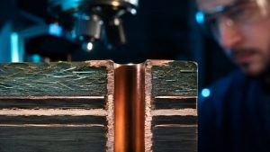
A microsection helps determine where the structure parted. Start with the expected interface and the observed damage, and document the cut location so the result can be interpreted against the drawing. A single section is local evidence, not a map of the entire perimeter. Preserve marked photos before cutting and record whether the specimen was sectioned before or after loading.
- Insert moves and the laminate remains visibly intact: inspect the coin and cavity wall for contact patterns or bonding residue; compare against a matched reference. Do not diagnose the cause from surface appearance alone.
- Board cracks near the opening: check whether the support loaded an unsupported area, and inspect a matched untested coupon before attributing damage to the original process.
- Peak is high but movement is uncertain: compare the trace with fixture travel and check for hard contact. If the endpoint was obstructed, repeat with the approved fixture and a new specimen.
Push Out Test Standard
Specify rigid-board workmanship and coin retention as separate acceptance requirements. When IPC-6012F (September 2023) is the edition invoked on the purchase documentation, §§1.3.1 and 1.3.1.1 cover performance classification and agreed deviations. Record the revision, amendments or addenda that apply, and the performance class called out for the order. Do not infer a class or coin retention value from the words “IPC compliant.”
Use the approved drawing or test plan for the coin-specific fixture, loading, conditioning, sample count, endpoint and limit unless the procurement documents explicitly invoke a different applicable requirement. A published copper-coin study may show a test arrangement, but its results are not your release threshold. Similarly, a standard for press-fit terminals in plated holes is not a default specification for a solid thermal insert.
Copper Coin PCB Design
Put the inspection in the drawing package before ordering prototypes. Identify the coin footprint, insertion direction, supportable area, face datums and sample construction. Then state which documents control mechanical retention, surface geometry and thermal verification. Without those details, procurement may receive a report with a clear force value but no defensible release decision.
Copyable worksheet: use this at first-article review or when a supplier changes the cavity, insert or bonding process. Put your required and reported values in the second column, then compare each item with the approved revision. The entries shown are examples, not production requirements.
| Field | Record or compare | Next action if missing |
| Identity and construction | Drawing revision, lot, specimen IDs, coin dimensions, cavity and attachment method. | Trace samples to the build before comparing lots. |
| Method and environment | Fixture drawing, push direction, rate, temperature, endpoint and conditioning profile. | Ask for the signed method and raw trace; repeat if conditions cannot be recovered. |
| Results and failure location | Individual values in N, sample count, traces in N and mm, and photos of what moved or fractured. | Request specimen-level evidence; an average alone cannot establish compliance for every sample. |
| Worked decision row | Example: report shows 240 N post-exposure, but the approved conditioned limit is missing. | Hold the retention decision. Obtain the approved limit; do not invent one from the baseline. |
For a Best Technology fabrication discussion, send the board and insert drawings and identify the exact revision and acceptance evidence you need at sales@bestpcbs.com. Confirm the scope of any requested test separately.
Frequently Asked Questions
Does a copper coin need to touch the heat sink?
The thermal path needs a defined interface to the cooling assembly, not necessarily bare copper touching bare metal. The package and system may require interface material, electrical isolation or controlled mounting pressure. A push-out report does not confirm any of those conditions.
Can a thermal via array replace the insert?
It may be an option when the design can meet its thermal budget without the solid copper path. Compare the real stackup, available area, usable via construction and mounting interface under the same load. Run the relevant thermal validation on the proposed replacement; there is no coin-retention result to transfer to a board without a coin.
Will the coupon tell me whether I can rework the component?
Not by itself. The coin changes the heat path during assembly and rework, but mechanical retention data alone does not describe heating balance at the package. Confirm the package and board rework requirements and use representative assemblies to evaluate the actual temperature profile and inspection results.
Can the copper insert also be tied to chassis ground?
Only if the electrical and mechanical drawings define that connection. Do not infer grounding from the presence of copper. Check the net assignment, contact arrangement and any insulation requirement between the board and the chassis; verify the electrical path using the relevant inspection plan.
Can I pool results from different coin sizes?
Keep them separate unless the approved plan explains why they represent the same acceptance population. Perimeter, shape and cavity wall geometry can affect the load path. Dividing force by the coin’s face area does not automatically produce a comparable bond-strength value.
What if the carrier panel makes the coupon stiffer than the finished board?
Document the carrier and support condition. A stiffer panel can change how the board deflects in the fixture. If the intended acceptance object is a finished board, ask the lab to confirm the coupon’s representativeness or test a matched finished geometry.
Can a high reading hide an off-center insert?
Yes. A mechanical load is not a measurement of position. Compare insert registration with the board datum and any nearby copper keepouts separately. For assemblies where the insert must align with a device thermal pad, include the applicable position check as a distinct drawing item.
What should a supplier provide if the insert material changes?
Request the revised material and drawing identification, the reason for the change and the qualification plan. Decide which measurements must be repeated against the original requirement. Do not carry over a previous revision’s mechanical or thermal evidence without establishing that the changed construction remains representative.
Technical References
- HF-Praxis 1/2018, copper coin retention test and force trace, Figure 11.
- Chen et al., copper coin-embedded PCB manufacture, thermal simulation and reliability.
- UIC Advanced Process Laboratory, Initial Evaluation of Copper Coin Reliability Risk Sites.
- IPC-6012F, scope and performance classification.