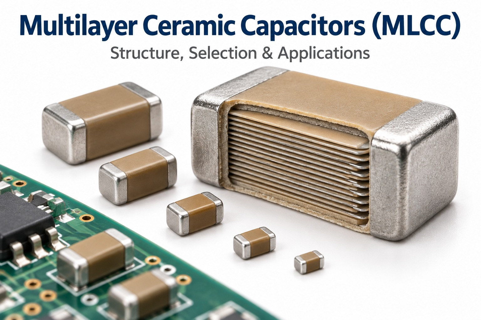
A multilayer ceramic capacitor is one of the most widely used passive components in modern electronics. It provides compact, low-inductance capacitance for decoupling, filtering, power stabilization, RF circuits, automotive electronics, industrial control, and many other applications.
Selecting an MLCC requires more than reading the value in the BOM. Dielectric type, DC bias, working voltage, case size, frequency, and PCB mechanical stress can all change how the capacitor behaves after assembly.
Key Takeaways
- A multilayer ceramic capacitor (MLCC) is a non-polarized capacitor built from alternating ceramic dielectric and metal electrode layers.
- C0G/NP0 offers high stability and low loss, while X7R and X5R provide much higher capacitance density.
- Nominal capacitance is not always the effective capacitance. Class II MLCCs can lose capacitance as DC voltage increases.
- Capacitance, working voltage, dielectric, case size, temperature range, ESR, ESL, self-resonant frequency, and termination type should be reviewed together.
- Most MLCCs are SMD chip components, but leaded, axial, radial, stacked, and low-inductance versions are also available.
- PCB bending, depaneling, screws, connectors, and rework can crack the ceramic body.
- Second-source approval should compare the exact electrical and mechanical behavior of the replacement part, not only its capacitance and package size.
What Is a Multilayer Ceramic Capacitor (MLCC)?
A multilayer ceramic capacitor (MLCC) is a non-polarized capacitor made from many alternating ceramic dielectric and metal electrode layers inside one compact monolithic body.
The phrase multilayer ceramic capacitor MLCC describes the same stacked, monolithic capacitor technology.
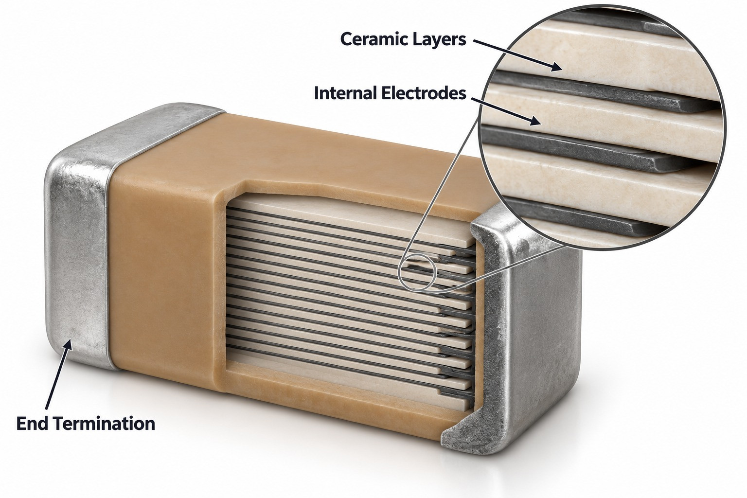
The internal electrodes are connected alternately to the two end terminations. This arrangement effectively places many small capacitor layers in parallel, allowing relatively high capacitance in a very small package.
A typical MLCC contains ceramic dielectric layers, internal metal electrodes, external end terminations, barrier plating, and a solderable outer finish. SMD chip versions dominate modern electronics, although the same multilayer ceramic technology can appear in other package formats.
How Does a Multilayer Ceramic Capacitor Work?
An MLCC stores charge between overlapping internal electrodes separated by very thin ceramic dielectric layers.
The basic relationship is:
Capacitance ∝ dielectric permittivity × electrode area ÷ dielectric thickness
This is why multilayer construction is effective. Capacitance can be increased by adding active layers, increasing electrode overlap, using higher-permittivity ceramic, or reducing dielectric thickness.
Because the electrode layers are connected in parallel, increasing layer count raises the total effective electrode area without greatly increasing the component’s external size.
What Are the Main MLCC Dielectric Types?
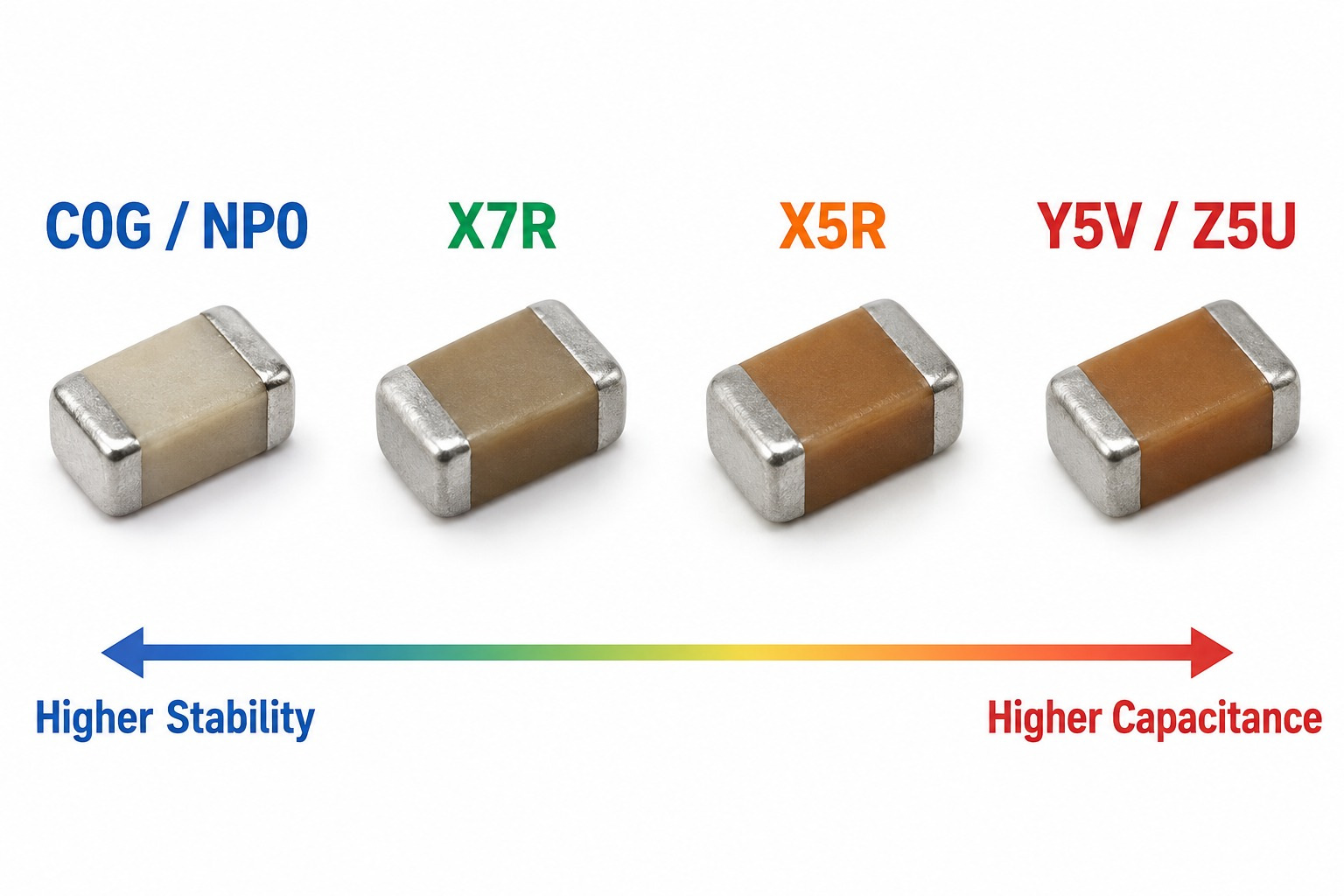
The main MLCC dielectric types are C0G/NP0, X7R, X5R, and lower-stability ceramics such as Y5V or Z5U.
| Dielectric | Main Characteristic | Typical Use |
|---|---|---|
| C0G / NP0 | Very stable, low loss | RF, resonant circuits, precision filtering |
| X7R | High capacitance density with moderate variation | General decoupling and power filtering |
| X5R | High capacitance density in compact packages | Low-voltage power rails and portable electronics |
| Y5V / Z5U | Very high nominal capacitance, poorer stability | Limited non-precision applications |
C0G is preferred when capacitance stability and low dielectric loss matter most. X7R and X5R are more common where higher capacitance density is needed for bypassing, decoupling, and power rails.
What Specifications Matter When Selecting an MLCC?
The most important MLCC specifications are effective capacitance, working voltage, dielectric type, package size, temperature range, ESR, ESL, self-resonant frequency, and termination type.
| Specification | Check Item |
|---|---|
| Capacitance | Required nominal value |
| Effective capacitance | Actual capacitance at operating voltage |
| Rated voltage | Electrical margin above working voltage |
| Dielectric | C0G, X7R, X5R or another class |
| Tolerance | Initial capacitance variation |
| Case size | PCB space and electrical behavior |
| Temperature range | Environmental requirement |
| ESR | Resistive loss and ripple behavior |
| ESL | High-frequency inductive behavior |
| Self-resonant frequency | Frequency range where the part remains capacitive |
| Termination type | Standard or flex-resistant construction |
| Qualification | Automotive or other reliability requirement |
Working voltage deserves particular attention. Two capacitors with the same nominal capacitance and voltage rating can deliver very different effective capacitance under the same DC bias.
For PCBA sourcing, the exact manufacturer part number is more useful than a generic BOM description such as “10 µF, 25 V, 0603.”
What Is the DC Bias Effect in MLCC Capacitors?
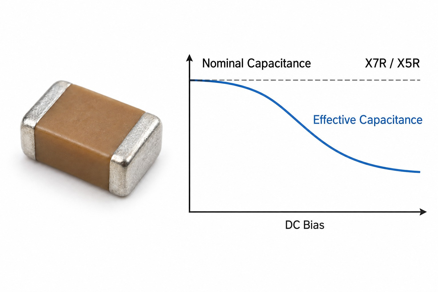
DC bias is the reduction in effective capacitance that occurs in many Class II MLCCs when DC voltage is applied.
This effect is especially important for X7R and X5R parts. A capacitor marked 10 µF does not necessarily provide 10 µF at its actual operating voltage.
The reduction depends on the dielectric formulation, rated voltage, applied voltage, nominal capacitance, case size, manufacturer series, and internal construction.
Engineers should therefore check the manufacturer’s capacitance-vs-voltage curve for the exact part number. For power rails and regulator input/output capacitors, effective capacitance at the real operating voltage is more useful than nominal capacitance.
What Are Multilayer Ceramic Capacitors Used For?
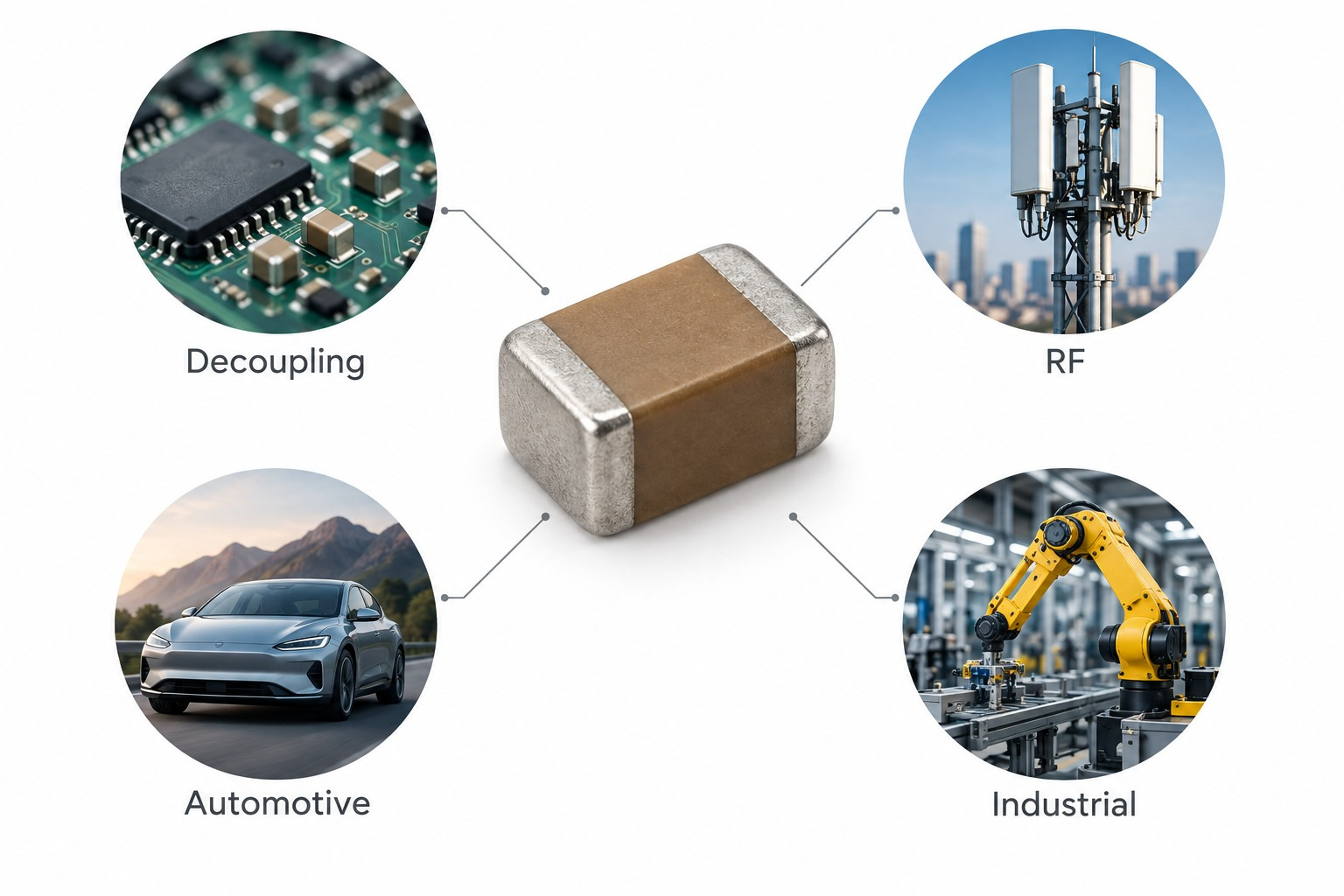
MLCCs are mainly used for decoupling, bypassing, power filtering, noise suppression, RF circuits, and signal conditioning.
Common multilayer ceramic capacitor applications range from local IC decoupling to power filtering, RF networks, and signal conditioning.
Typical applications include processor and MCU power decoupling, FPGA and memory rails, DC-DC converters, LDO stabilization, RF matching, resonant circuits, automotive ECUs, industrial electronics, medical electronics, and communication equipment.
For RF and precision circuits, C0G/NP0 parts are commonly selected because their capacitance remains more stable. Automotive applications may add qualification and flex-resistant termination requirements.
SMD, Chip, Leaded and Axial MLCCs: What Is the Difference?
MLCCs are available in several package styles, although SMD chip MLCCs are by far the most common in modern PCB assembly.
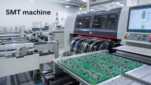
An SMD multilayer ceramic capacitor is optimized for automated pick-and-place and reflow assembly.
SMD chip MLCCs support automated placement and reflow. Leaded, axial, and radial versions serve through-hole or legacy applications, while stacked and low-ESL constructions address higher capacitance, ripple, or high-frequency requirements.
MLCC therefore describes the internal capacitor technology, not one fixed external package.
How Are Multilayer Ceramic Capacitors Manufactured?
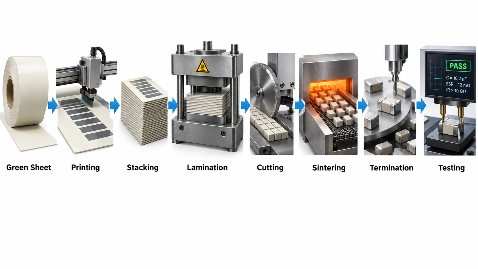
MLCCs are manufactured by forming thin ceramic sheets, printing internal electrodes, stacking and laminating the layers, sintering the ceramic body, and then adding external terminations and electrical testing.
The multilayer ceramic capacitor manufacturing process controls layer thickness, electrode registration, densification, termination quality, and final electrical performance.
The main production sequence is:
Green Sheet → Printing → Stacking → Lamination → Cutting → Sintering → Termination → Testing
Uniform ceramic thickness, electrode alignment, lamination pressure, firing conditions, and termination quality all affect final capacitance and reliability.
MLCC vs Tantalum vs Film Capacitor: What Is the Difference?
MLCCs are generally smaller and lower in ESR/ESL, tantalum capacitors provide more stable capacitance under DC bias, and film capacitors are often preferred for high stability, higher voltage, or power applications.
| Factor | MLCC | Tantalum | Film Capacitor |
|---|---|---|---|
| Polarity | Non-polarized | Polarized | Usually non-polarized |
| Size | Very compact | Compact | Usually larger |
| ESR / ESL | Very low | Moderate | Application dependent |
| DC bias effect | Important for Class II | Much smaller | Generally low |
| Capacitance stability | Depends on dielectric | Relatively stable under bias | Generally stable |
| Mechanical concern | Ceramic flex cracking | Different failure modes | Less ceramic-flex sensitivity |
| Typical use | Decoupling, filtering, RF | Bulk capacitance, power rails | Power, filtering, precision |
The final choice should be based on actual voltage, frequency, ripple current, temperature, PCB space, and reliability requirements.
What PCB Layout Rules Matter for MLCCs?
MLCC layout should minimize electrical loop inductance and mechanical PCB strain.
For decoupling, place the capacitor close to the relevant IC power pin, keep the power and ground connections short, and use low-inductance vias where appropriate.
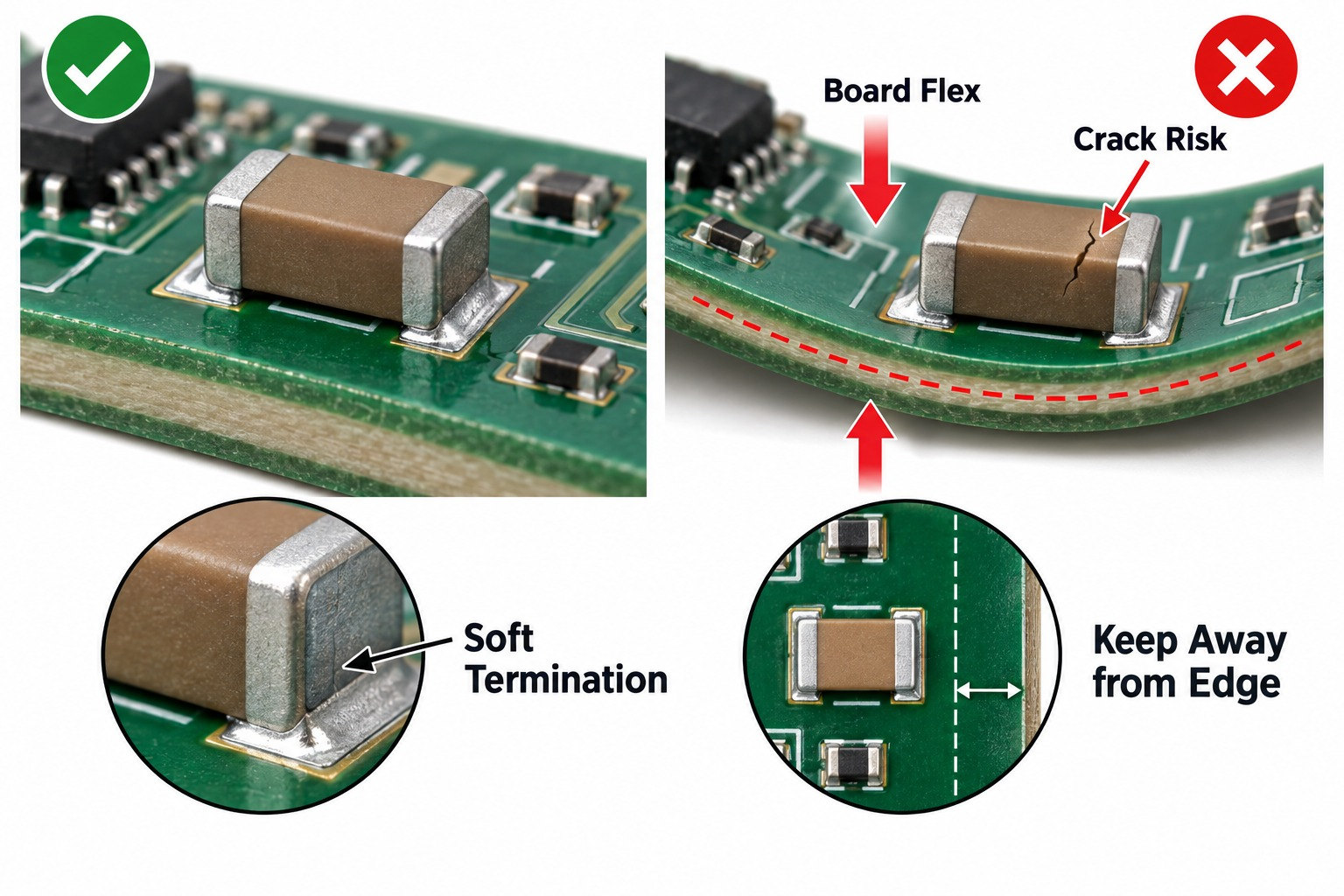
Mechanically, avoid placing sensitive ceramic capacitors immediately beside V-score lines, routing tabs, screw holes, large connectors, press-fit components, board edges, or other high-flex regions.
Pad geometry should follow the component manufacturer’s recommended land pattern, while component orientation and flex-resistant termination options should be considered for mechanically demanding assemblies.
What Causes MLCC Cracking and Failure?
MLCC cracking is mainly caused by mechanical strain transferred from the PCB into the brittle ceramic body.
Common sources include PCB bending, depaneling, screw tightening, connector insertion, press-fit operations, mechanical shock, thermal shock, rework, and unsuitable pad geometry.
Soft-termination or flex-resistant MLCC series can absorb part of the board strain, while keeping MLCCs away from high-flex board edges and separation lines reduces the mechanical load transferred into the ceramic.
Who Are the Major Multilayer Ceramic Capacitor Manufacturers?
Major MLCC manufacturers include Murata, TDK, Samsung Electro-Mechanics, Taiyo Yuden, Yageo/KEMET, KYOCERA AVX, Vishay, and Walsin.
These suppliers serve consumer, automotive, industrial, telecommunications, computing, RF, and high-reliability markets. Their parts should not be treated as automatically interchangeable even when nominal capacitance, voltage, dielectric, and case size appear identical.
Second-source approval should compare DC bias behavior, effective capacitance, ESR, ESL, temperature characteristics, termination design, qualification, and lifecycle status.
What Should Buyers Check Before Approving an MLCC for PCBA?
Buyers should verify the exact part number, effective capacitance, voltage rating, dielectric, case size, temperature class, termination, qualification, and lifecycle status before approving an MLCC.
| Check Item | Why It Matters |
|---|---|
| Manufacturer + exact P/N | Prevents ambiguous substitution |
| Nominal capacitance | Basic circuit requirement |
| Effective capacitance | Real capacitance under operating bias |
| Rated voltage | Electrical margin |
| Dielectric | Stability and capacitance density |
| Tolerance | Initial value range |
| Case size | PCB area and electrical behavior |
| Temperature range | Environmental compatibility |
| Termination type | Mechanical reliability |
| Qualification | Automotive or other reliability requirements |
| Lifecycle status | Long-term sourcing |
| Approved alternative | Supply continuity |
| Reel/package information | SMT production compatibility |
For automotive or mechanically demanding assemblies, check whether a flex-resistant or soft-termination series is required. For power applications, review effective capacitance at the actual working voltage before approving an alternate part.
FAQ About Multilayer Ceramic Capacitors
1. What does MLCC stand for?
MLCC stands for Multilayer Ceramic Capacitor.
2. Are multilayer ceramic capacitors polarized?
No. Standard MLCCs are non-polarized and can be installed in either electrical orientation.
3. Is X7R better than C0G?
No. C0G provides better capacitance stability and lower loss, while X7R provides much higher capacitance density.
4. Why does an MLCC lose capacitance under voltage?
Class II ceramic dielectrics such as X7R and X5R can lose effective capacitance when DC voltage is applied. The amount depends on the exact part construction.
5. Can MLCCs crack on a PCB?
Yes. PCB bending, depaneling, connector forces, screw mounting, press-fit operations, rework, and mechanical shock can crack the ceramic body.
6. Are all MLCCs SMD components?
No. SMD chip MLCCs are the most common, but leaded, axial, radial, stacked, and specialized low-inductance versions are also available.
A multilayer ceramic capacitor should be selected based on its actual operating behavior, not only the capacitance value in the BOM. Dielectric type, DC bias, working voltage, frequency behavior, package size, PCB placement, and mechanical loading all influence finished-PCBA reliability.
For projects requiring PCB fabrication, component sourcing, SMT assembly, inspection, and functional testing, send your Gerber files, BOM, assembly drawings, approved component list, and test requirements to sales@bestpcbs.com for DFM and PCBA review.