A PCB inspection microscope enlarges accessible board and assembly surfaces so an inspector can examine fine copper features, pads, component leads, solder fillets and contamination. It is most useful when a specific visible feature needs a closer look or a photograph for a defined inspection decision. It cannot see through a BGA package or prove that an apparently sound connection conducts electricity.

For a PCB or PCBA order, the practical question is not simply how powerful the microscope is. The drawing, suspected defect, viewing angle, illumination and acceptance requirement determine what the image can establish. At EBest Circuit (Best Technology), our quality equipment includes AOI, electrical testing and microsection imaging; magnified visual review has a narrower job alongside those methods.
What Is a PCB Inspection Microscope?
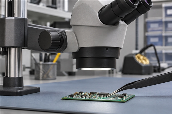
A PCB inspection microscope is a stereo or digital optical system used to enlarge the visible surface of a printed circuit board. Stereo optics provide depth perception through separate viewing paths. A digital system displays and can capture an image on a screen. Both depend on a clear line of sight to the feature being inspected.
A microscope does not decide whether a condition is acceptable by itself. The inspector still needs the relevant drawing, product class or approved workmanship criterion, the process stage and the location of the feature. Magnification is a way to gather evidence, not an acceptance limit.
What Can It Reveal on a Bare PCB?
On an exposed bare board, a microscope can help resolve a suspected trace nick, solder-mask encroachment, surface particle, pad damage or irregular plated-hole entrance. Lower magnification locates the feature relative to nearby pads and tracks; a closer view tests whether the apparent defect is actual material damage or a lighting effect.
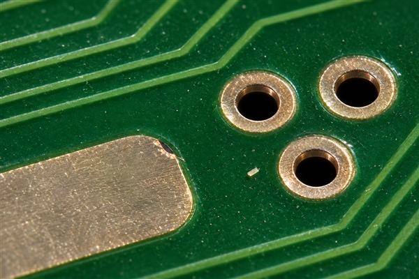
The observation stops at the visible surface. On a fine-feature HDI board, a close-up can locate a suspected nick beside a microvia land, but it cannot establish the buried connection. Similarly, a picture of a hole mouth on a fabricated FR4 PCB cannot establish copper thickness or continuity deeper in the barrel. Those questions may call for electrical testing or a prepared microsection.
What Can It Reveal on a PCB Assembly?
On a PCB assembly, magnification can make exposed lead-to-pad alignment, a solder bridge, lifted gull-wing lead, displaced small part or foreign particle easier to evaluate. A stereo view is particularly helpful where height and the shape of a visible fillet matter.
Appearance must be interpreted against the actual package and assembly requirement. A dark line between two pins may be shadow; a bright line may be reflected light rather than solder. The inspector should change the viewing or lighting angle before treating either as a defect. An image of a visible fillet also cannot establish the hidden interface beneath a bottom-terminated component.
When Is Microscope Inspection Used in Production?
Microscope inspection is most valuable as a targeted follow-up: after a visual or AOI flag, when an incoming board has an ambiguous feature, after local rework, or during failure analysis. It is less suited to scanning every feature on every high-volume panel than a properly programmed automated optical inspection process.
At our PCB and assembly stages, the evidence chain should match the question. AOI can screen visible features repeatably; a microscope can clarify an individual location from another angle; electrical test checks specified connections; a prepared cross-section reveals internal construction. Each method answers a different part of the inspection question.
| Question on the board | What magnified viewing can establish | Evidence needed if the concern remains |
|---|---|---|
| Are two exposed leads joined by solder? | A clear view of the named lead gap from useful angles can show a visible bridge. | Compare with the circuit netlist; add an appropriate electrical check before calling it an unintended short. |
| Is a surface particle present near pads? | It can locate and image the visible particle. | Material identity or cleanliness risk may require separate analysis; appearance alone does not identify the substance. |
| Is a plated hole sound through the board? | It can show the accessible hole entrance only. | Electrical testing and, if internal construction is in question, an approved microsection. |
| Are hidden BGA balls joined correctly? | It cannot see the concealed ball interfaces. | Use an appropriate X-ray and electrical or functional test plan for the actual failure mode. |
The dividing line is accessibility. If the suspected feature is exposed, microscope images may settle a visual question; if it is inside the board or under a package, increasing zoom cannot recover the missing line of sight. This distinction determines the next inspection stage before anyone requests more photographs.
How Much Magnification Is Useful for PCB Inspection?
For general PCB inspection, Leica describes roughly 5x to 30x as a practical stereo or digital range: around 5x gives a board-area overview, while approximately 25x to 30x reveals finer surface detail. This is an application guideline, not a universal IPC acceptance magnification or a specification for our equipment.
Start with enough field of view to identify the correct component and orientation. Then increase magnification until the suspected feature is clear, keeping a reference view so the close-up can be located on the board. Jumping directly to the highest setting can hide the surrounding pins, reduce depth of field and make a shadow look like an isolated defect.
The actual usable detail also depends on optical resolution, camera sampling, focus and illumination. A large number printed on a digital microscope does not guarantee that two adjacent features can be resolved. The applicable work instruction or acceptance standard, not a generic blog range, sets the magnification required for a formal judgment.
How Do Lighting and Viewing Angle Change What You See?
Illumination changes contrast. A ring light can illuminate a broad area evenly, but shiny solder may reflect directly into the optics and hide its contour. Diffused or oblique light can reveal a fillet edge or a particle that looked like solder under direct lighting. The same suspect location should be examined under more than one condition when reflection affects the judgment.
Angle matters just as much. A near-vertical view helps locate a feature among neighboring pads; a suitable side view can clarify a raised lead or exposed solder profile. Tall parts, shields and connectors may block the line of sight altogether. Leica’s inspection examples show how changing illumination can reveal different PCB details, including holes and recesses.
What Are the Detailed Parameters of a PCB Inspection Microscope?
Useful parameters describe the whole viewing arrangement, not magnification alone. The table below uses one published equipment example, the Leica A60 H, so that the values belong to a consistent optical configuration. They are manufacturer specifications for that microscope, not EBest Circuit equipment specifications or universal requirements for PCB acceptance.
| Parameter | Leica A60 H published value | What it changes during PCB work |
|---|---|---|
| Zoom range | 8x-48x | Moves from area orientation to detail without changing instruments. |
| Maximum object field | 30 mm | Determines how much of the board can be seen at the low end of the zoom range. |
| Working distance | 122 mm without illumination | Leaves room for the board and, when appropriate, a probe or rework tool; an illuminator can change available clearance. |
| Maximum depth of field | 10.3 mm | Helps keep features at different heights in focus at the relevant low-zoom setting; it is not constant across zoom. |
| Illumination | LED ring light with removable diffuser | Allows a more diffuse view of reflective solder. |
These values come from the Leica A60 H brochure and specification table. Its detailed optical table shows that a larger magnification gives a smaller field and shallower depth: 8x corresponds to a 30 mm object field and up to 10.3 mm depth of field, whereas 20x corresponds to a 12 mm field and 2 mm depth of field. The useful decision is therefore not “choose 48x”; it is whether the feature remains visible, in focus and correctly located at the working setting.
If a customer requests dimensional evidence rather than a qualitative photograph, the setup also needs a calibrated scale or reticle, a stated measurement method and the correct feature definition. A nominal zoom number alone cannot support a reported trace width or defect dimension.
Stereo vs Digital PCB Inspection Microscope: Which Fits the Task?
A stereo microscope is the stronger fit when depth perception and hands-on access matter, such as judging an exposed fillet while repositioning a board. A digital microscope is useful when several people need to review or save the same image. Neither type can turn an inaccessible joint into a visible one.
| Inspection task | Stereo viewing | Digital viewing |
|---|---|---|
| Assess exposed lead height or fillet shape | Direct binocular depth cues help interpret height. | May need extra angles or focus changes to communicate depth. |
| Share a suspected defect with a customer | Requires a camera attachment or separate capture method for a common image. | Screen capture can simplify joint review and annotation. |
| Move around a tall assembled board | Check stand reach and working distance for the actual board. | Check camera clearance, stand reach and display latency for the actual board. |
| Inspect hidden BGA balls | Not visible through the package. | Not visible through the package. |
For an isolated assembly concern, a stereo view plus a camera can serve both examination and documentation. For repeatable photo review across teams, a digital capture workflow may be more convenient. The choice still depends on optical resolution, lighting, board size and the required record, rather than the word “digital” or the advertised maximum zoom.
How Do You Inspect a Suspected Solder Bridge?
First identify the exact component and two exposed pins using the assembly drawing and board orientation. Consider an illustrative small-outline IC whose adjacent leads appear joined in an AOI image. At a low microscope setting, retain a view showing the component marking and the suspect side. Then increase magnification only enough to inspect the gap between the named leads.
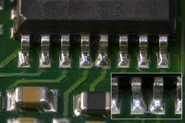
Now change the light or viewing angle. If a bright line moves with the reflection while the physical gap remains visible, the original picture was not sufficient evidence of a bridge. If metal appears continuous between the two leads from more than one useful angle, record the location and image before rework. Do not infer the condition of all the other pins from that one close-up.
The next action depends on what was actually observed. A visible connection calls for disposition against the assembly requirement and, where appropriate, controlled rework followed by repeat inspection. An ambiguous optical finding may need another view rather than immediate soldering. Electrical continuity between the two nets can help investigate the fault, but the circuit may contain legitimate connections elsewhere; compare the measurement with the approved schematic or netlist before calling it a short.
For this lead-gap scenario, the useful output is a traceable location, a clear before/after record when rework occurs, and an electrical check aligned with the circuit. A close-up without the component identity and net context cannot support the same decision.
Can a Microscope Inspect Hidden BGA Solder Joints?
No conventional optical microscope can see through a BGA package and the board to judge the full solder-ball interface. It may show a package edge, adjacent contamination or an externally accessible corner, but a clean edge view does not prove that hidden balls are connected.
Where the actual risk concerns concealed joints, define an X-ray or other suitable inspection and an electrical or functional test as appropriate to the product. X-ray can reveal selected internal geometry and defects, but its image still needs interpretation and may not settle every failure mode. An optical close-up should not be presented as a substitute for hidden-joint evidence.
How Do You Record a Microscope Inspection Finding?
A useful inspection image is traceable to the board and the requirement. Record the board revision, side, reference designator or coordinate, the feature of concern, the viewing direction, actual magnification or scale method, illumination condition and the applicable acceptance document. Keep both an orientation image and a close-up when the close-up alone cannot identify the location.
For a dimensional claim, include calibration or scale evidence and the measurement endpoints. For a qualitative finding, state what is visible and what remains unverified. IPC’s inspection-training syllabus explicitly distinguishes optical, automated and X-ray methods and calls for appropriate magnification and measurement-tool calibration; it does not make one photograph a universal pass/fail standard.
For the illustrative lead-gap case, the record would point to the named pins and board side, retain the overview and close-up under stated lighting, then append the disposition and any post-rework check. That sequence lets another engineer re-examine the same physical question rather than guess what a cropped image represents.
What Can a Microscope Confirm After Rework?
After local rework, a microscope can show whether accessible leads are aligned, whether the visible bridge is gone, and whether nearby pads or components appear damaged. A before/after pair taken from comparable angles is more useful than two unrelated close-ups. Inspection should also include adjacent features affected by heat or tool contact, not only the original pin gap.
The visual result is one part of release. A solder joint that looks acceptable may still have an electrical open, a damaged component or an intermittent connection. The repair record should name the additional electrical or functional check required by the approved process; optical inspection does not silently certify the whole assembly.
What Should Customers Specify for Magnified PCB Inspection?
For a PCB inspection microscope request, specify the feature, not only “inspect under microscope.” On a prototype, identify the component or board coordinate, suspected condition, assembly or fabrication drawing revision, acceptance document and whether the request is for a photo, measurement, rework decision or failure analysis. A PCB prototype with one suspect pad calls for a different record from routine lot screening.
Agree on coverage and output before production: every unit or a defined sample, which sides or locations, what images or measured values should be returned, and which finding triggers a hold or engineering review. If a hidden feature or internal hole wall is the real concern, specify X-ray, electrical test or microsection work instead of asking a surface photograph to answer it.
Send the drawing, Gerber or ODB++ data, BOM and assembly drawing where relevant, along with the inspection question, to sales@bestpcbs.com. We can align the request with the PCB or assembly work being quoted and identify which evidence the proposed inspection stage can actually provide. This is more precise than adding an unexplained “microscope inspection” line to a purchase order.
PCB Inspection Microscope FAQs
Can a large PCB be inspected without cutting it? Usually, if the microscope stand has enough reach and working distance to place the target beneath the optics. Check the actual panel dimensions, edge clearance and the height of nearby components before selecting the inspection position; a stated zoom range does not answer that fit question.
When should a microscope image include a scale? Include a calibrated scale whenever the finding depends on a dimension rather than appearance alone. Record the setup and measurement endpoints so another reviewer can distinguish a measured feature from a visually estimated one.