A medical LED MCPCB must do more than hold LEDs in position. It has to move heat away from the LED array, maintain the mechanical relationship between the LEDs and optics, and give the medical-equipment manufacturer a repeatable platform for electrical and optical validation.
EBest Circuit supports medical-lighting projects from substrate review and PCB fabrication through component sourcing, SMT assembly and customer-defined testing. This gives buyers one manufacturing workflow for the bare board and assembled LED module, with the approved revision, materials and production records linked to the order. Send your Gerber files, BOM, CPL, drawings, operating conditions and required tests to sales@bestpcbs.com for a project-specific review.
How Does LED Junction Temperature Affect Medical Lighting?
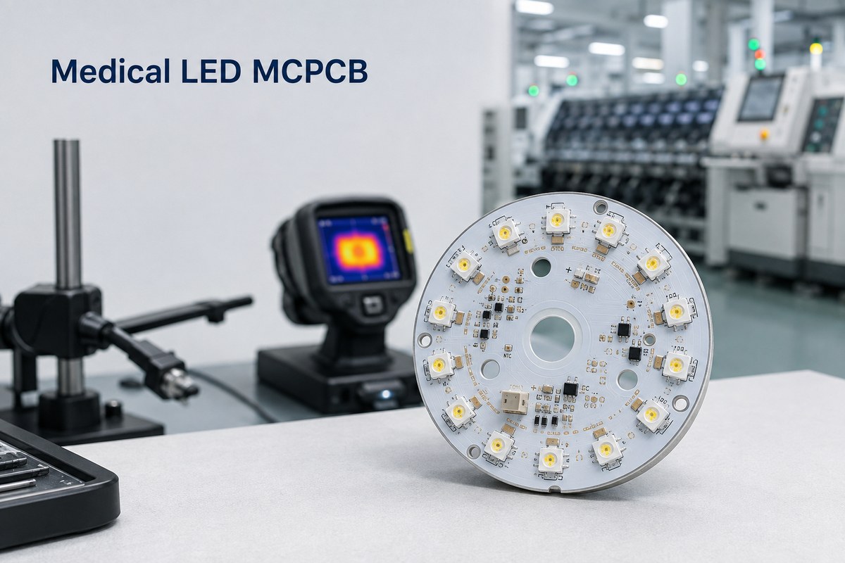
LED junction temperature affects light output, color stability and service life. In a surgical light, examination lamp or diagnostic light source, heat that remains around the LED junction can make optical performance less stable during extended operation.
The PCB is one part of the complete thermal path:
- LED package to solder joint: Pad design, solder coverage and voiding influence how effectively heat leaves the LED package.
- Circuit layer to dielectric: The dielectric must provide the specified electrical isolation without creating unnecessary thermal resistance.
- Metal or ceramic substrate: The substrate spreads heat away from localized LED hot spots.
- Board to heat sink: Board flatness, mounting pressure and the thermal-interface material affect contact with the heat sink.
- Heat sink to operating environment: Enclosure design, airflow and duty cycle determine whether the complete assembly can release the heat.
This is why selecting a material by thermal-conductivity value alone is not enough. Before quotation, the manufacturer should review the LED power, board outline, copper distribution, dielectric requirement, mounting method, heat sink, ambient temperature and operating cycle. Thermal acceptance limits should then be defined for the assembled equipment under the customer’s intended test conditions.
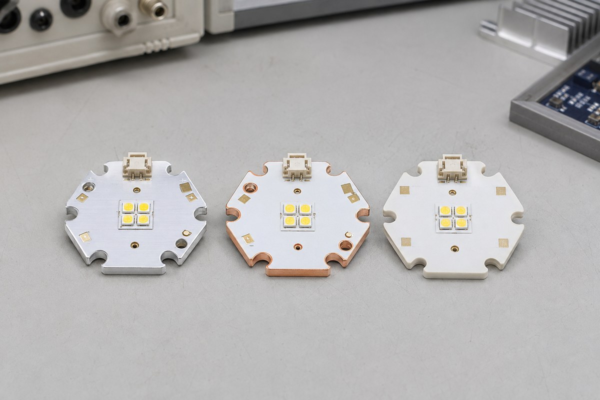
Which Substrate Should You Choose for a Medical LED MCPCB?
The right substrate depends on heat density, electrical-isolation requirements, board geometry, weight, budget and the way the board connects to the heat sink.
| Substrate | Best fit | Buyer benefit |
|---|---|---|
| Aluminum MCPCB | Surgical, examination and general medical-lighting boards with moderate-to-high heat loads | Practical thermal performance with competitive cost and weight |
| Copper-base PCB | Compact, high-power LED arrays with concentrated heat | Faster heat spreading from local hot spots |
| Ceramic PCB | Compact modules requiring high thermal stability and electrical insulation | Direct thermal and insulation performance without a metal-core dielectric stack |
Aluminum MCPCB is often the practical starting point for medical LED lighting. Copper base may be justified where the LED array creates concentrated heat that aluminum cannot spread effectively within the available space. Ceramic substrates can suit compact light sources or assemblies where thermal stability, insulation and dimensional control outweigh material cost.
The final choice should be made against the released design. EBest can compare the required board thickness, copper weight, dielectric construction, isolation voltage, surface finish, flatness and mounting details before confirming the build.
How Can Medical LED PCB Assembly Maintain Brightness and Color Consistency?
Consistent illumination starts with controlled components and repeatable assembly. The PCB manufacturer cannot correct an unspecified LED binning strategy after the LEDs have been purchased and mounted.
Medical-lighting buyers should control:
- Approved LED part number and bin: Specify the permitted luminous-flux, color-temperature, wavelength or forward-voltage bin in the BOM or purchasing specification.
- Lot consistency: Define whether one LED lot or matched bins are required within each board, lamp head or production order.
- Polarity and placement: Use clear polarity marks and machine-readable placement data so every LED follows the approved optical layout.
- Solder-paste deposition: SPI can check solder-paste volume, area and height before component placement.
- Placement accuracy: AOI can verify presence, position, orientation and visible solder-joint conditions after reflow.
- Reflow control: A controlled profile helps reduce solder variation and thermal stress on LEDs and nearby components.
- Board-level operation: Powering the LEDs before shipment identifies open circuits, polarity errors and non-operating devices before system installation.
If brightness or color uniformity is an acceptance requirement, the RFQ should also define the measurement equipment, test distance, drive current, warm-up time, sampling plan and pass/fail limits. That turns “consistent light” into a result both parties can verify.

Which White Solder Mask Is Suitable for Medical LED PCBs?
White solder mask can improve reflectance around an LED array, but color alone does not define its suitability. Buyers should consider initial reflectance, resistance to yellowing, adhesion, surface appearance and compatibility with the assembly temperature profile.
The manufacturing package should state:
- the approved white solder-mask type or agreed equivalent;
- required color and appearance standard;
- areas where mask thickness or clearance is critical;
- acceptable discoloration after the specified thermal exposure;
- inspection method and cosmetic acceptance limits.
A highly reflective surface can support optical efficiency, while a mask that discolors during reflow or long-term operation can affect appearance and light distribution. For this reason, the solder mask should be evaluated with the actual LED wavelength, operating temperature and optical structure—not selected from a catalog description alone.
Some medical LED assemblies use black or another dark solder mask to manage stray light or match the optical design. The correct choice follows the equipment’s optical requirement; white should not be treated as a universal rule.
What Testing Should Medical LED MCPCB Manufacturing Include?
Testing should verify the requirements that determine whether the assembled board can move into the customer’s lighting system. The required scope depends on the board design and the medical-equipment manufacturer’s validation plan.
| Test or inspection | What it helps verify |
|---|---|
| Bare-board electrical test | Opens and shorts against the released PCB data |
| Dimensional inspection | Outline, thickness, mounting holes and critical positions |
| SPI and AOI | Solder-paste deposition, placement, polarity and visible assembly defects |
| X-ray when applicable | Hidden joints, thermal pads or voiding that cannot be judged visually |
| Dielectric or Hi-Pot test | Customer-defined electrical-isolation requirement |
| LED operation test | Correct polarity and operation before installation |
| Thermal test | Temperature at agreed locations under defined power and ambient conditions |
| Optical test | Customer-defined brightness, color temperature, wavelength or uniformity limits |
| Functional test | Board-level input, control, dimming or communication functions |
The RFQ should identify which tests are required, who supplies the fixture and procedure, how many units are tested, and which records must accompany the shipment. EBest can review the proposed test points, power conditions, fixtures and acceptance limits before production so that the quotation reflects the actual verification work.
How Should Medical LED PCB Materials and Production Lots Be Traced?
Traceability helps a buyer connect a delivered LED assembly to the correct files, materials, components and inspection records. It is especially useful when the product moves from prototype approval to repeat production.
The required record set may include:
- Released revision: Gerber files, BOM, CPL, assembly drawings and approved engineering changes.
- PCB materials: Core or base material, dielectric construction, solder mask and surface finish.
- LED identity: Manufacturer, part number, date or lot code, and approved bin where required.
- Other critical components: Supplier and production-lot information defined by the customer.
- Production batch: Work order, assembly lot and relevant process dates.
- Inspection and testing: Bare-board test, SPI, AOI, X-ray, electrical, functional, thermal or optical records included in the agreed quality plan.
- Change history: Approved substitutions or process changes linked to the applicable production lot.
The customer should define the required traceability level and record-retention period before ordering. EBest operates under ISO 9001 and ISO 13485 quality systems and can align the order records and inspection deliverables with the agreed medical-lighting project requirements.
Case Study: Medical LED MCPCB Production at EBest
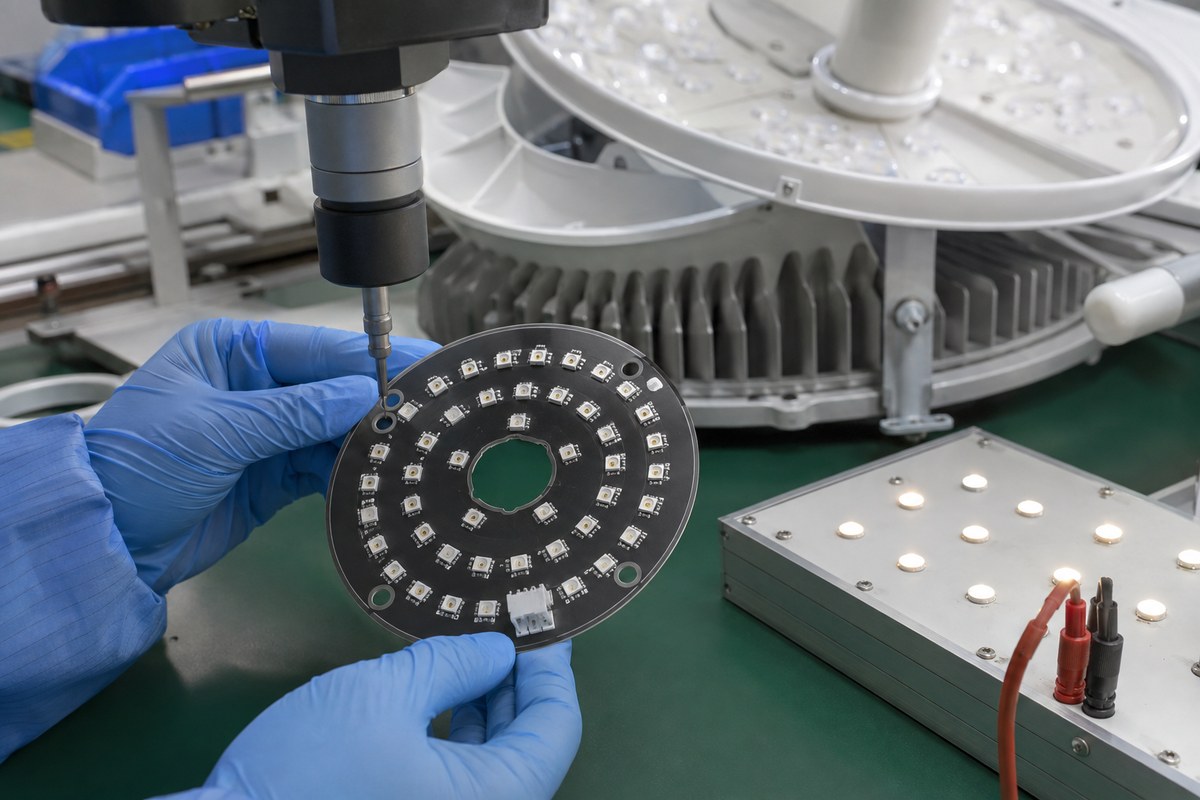
A surgical-lighting customer needed a completed LED assembly that could proceed to installation, rather than a bare metal-core board from one supplier and assembly from another. EBest coordinated the aluminum PCB, component procurement and SMT assembly under one order.
| Item | Project detail |
|---|---|
| Application | Surgical-lighting LED board |
| Construction | Single-sided aluminum-core PCB |
| Thickness | 1.6 mm ±10% |
| Copper | 1 oz |
| Surface finish | Lead-free HASL |
| Mask / legend | Black solder mask / gray legend |
| Scope | PCB, component sourcing and SMT assembly |
| Completion | Within 1.5 weeks |
The production requirements focused on details that affected the customer’s next assembly step:
- LED positions followed the approved optical layout: Placement-offset requirements kept assembly aligned with the released design.
- Mounting holes were measured before shipment: Optical measurement checked the critical hole positions needed for installation.
- Every LED was checked for operation: The customer received assembled boards with a board-level operation check completed before integration.
- Boards were cleaned for delivery: Solder balls, rosin and other visible residues were controlled before shipment.
The customer received the fabricated board, sourced components and completed SMT assembly in one coordinated delivery. The 1.5-week completion time applies to this project; schedules for other medical LED assemblies depend on material availability, board construction, quantity and required testing.
Why Choose EBest for Medical LED MCPCB Manufacturing?
EBest helps medical-lighting buyers convert released product requirements into a controlled PCB and assembly order.
- A thermal structure matched to your LED assembly: Aluminum, copper-base and ceramic options can be reviewed against the heat load, insulation requirement and mechanical interface.
- Fewer supplier handoffs: PCB fabrication, component sourcing and SMT assembly can be coordinated through one manufacturing workflow.
- Earlier detection of production risks: DFM and BOM review can identify unclear materials, footprints, polarity, mounting details and test requirements before the build.
- Inspection matched to your board: Electrical testing, SPI, AOI, X-ray and customer-defined functional testing can be assigned according to the actual assembly.
- Traceable repeat orders: Approved files, specified materials, LED information, production lots and agreed inspection records can remain linked to the order.
- Quality systems relevant to medical projects: EBest holds ISO 9001 and ISO 13485 certifications, with IATF 16949 and AS9100D supporting additional controlled manufacturing requirements where applicable.
- A clear delivery plan: Lead time is confirmed after reviewing board complexity, component availability, quantity and test scope; the surgical-lighting project above was completed within 1.5 weeks.
To receive a useful quotation, send the Gerber files, BOM, CPL, assembly drawings, LED bin requirements, board quantity, heat-sink details and required test plan. EBest will review what can be manufactured, which details need confirmation and what evidence can be delivered with the order.
FAQs About Medical LED MCPCB
Is every medical LED PCB an MCPCB?
No. Aluminum and copper-core MCPCBs are common when the LED array needs an efficient thermal path, but FR4, ceramic and other constructions may be appropriate for different power, insulation, space and cost requirements.
Is copper always better than aluminum for medical LED lighting?
Copper spreads heat more effectively, but it is heavier and more expensive. Aluminum is often sufficient when the thermal load and heat-sink design are compatible. The choice should follow the actual thermal and mechanical requirements.
Should a medical LED PCB always use white solder mask?
No. White solder mask is useful when reflectance supports the optical design. Black or another color may be required to control stray light or meet the equipment’s appearance requirements.
Can EBest source LEDs by a specified brightness or color bin?
EBest can source components against the approved manufacturer part number and customer-defined bin requirement. Permitted bins, lot-matching rules and substitution restrictions should be stated in the BOM or purchasing specification.
Which files are needed for a medical LED PCBA quotation?
Provide the Gerber files, BOM, CPL, assembly drawings, quantities, LED specifications, operating conditions, critical dimensions and required electrical, thermal, optical or functional tests.
Can the MCPCB manufacturer guarantee the finished medical light’s performance?
The manufacturer can verify agreed board and assembly requirements. Finished-equipment optical performance, thermal performance and service life must be validated in the complete lighting system under its intended operating conditions.
Ready to move your medical-lighting board from files to an assembled, testable unit? Send your project package to sales@bestpcbs.com for a manufacturing review and quotation for your medical LED MCPCB.