Ceramic substrate mounting needs a defined load path, suitable support and a controlled thermal interface. Do not pull a bare ceramic circuit flat with screws or copy a packaged power module’s mounting torque onto an unqualified ceramic plate. A module housing or pressure system can distribute load in ways that a bare substrate does not.
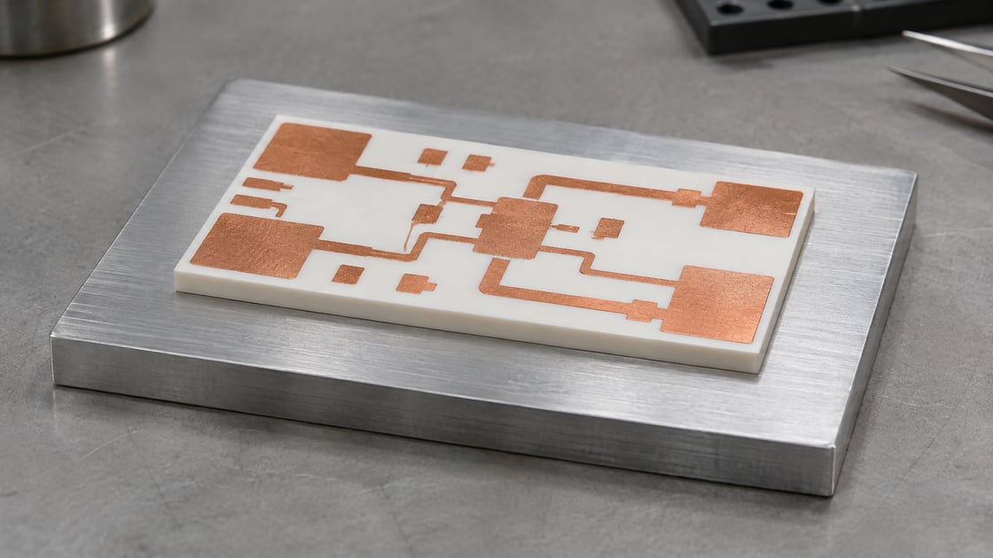
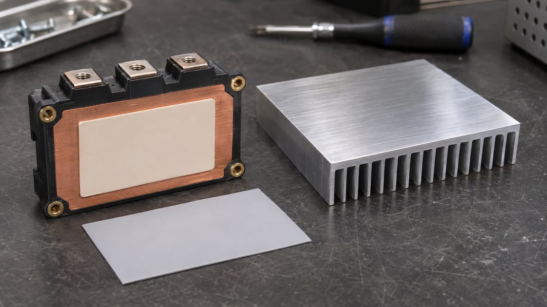
Consider a hypothetical copper-patterned ceramic circuit intended to sit on an aluminum heat spreader. Its underside must make useful thermal contact without being forced to bridge an unsupported gap. This guide shows how to review that mechanical interface; it does not provide a universal torque, clamping pressure or installation recipe.
Identify the Product Being Mounted
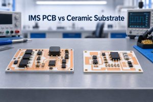
A bare ceramic circuit, a ceramic-based power module and a baseplate-equipped package are different mechanical objects. Start with the exact part drawing and assembly construction. The word ceramic alone does not identify the surface to clamp or the component designed to carry fastening load.
A bare substrate exposes the circuit carrier directly. A packaged module may include a housing, spring elements, terminals and specified fastening points. A metal baseplate adds another structural and thermal interface. Treat these as different designs rather than three versions of the same screw-mounting problem.
Collect Detailed Mounting Parameters
The review needs dimensions and limits for the actual assembly. Record where each requirement comes from and what surface it applies to. Missing force, support or flatness limits should remain engineering questions, not numbers copied from an unrelated module.
| Input | Identify |
| Substrate | Material, thickness, outline, copper pattern |
| Support | Contact region and unsupported span |
| Mating surface | Flatness, roughness, steps, cleanliness |
| Retention | Load points and approved force basis |
| Thermal interface | Material, coverage and thickness basis |
| Environment | Temperature range, cycling, vibration |
For a product-specific numerical example, SEMIKRON’s SKiM4/5 mounting instruction, revision 4.0, May 2017 specifies heatsink unevenness no greater than 50 µm per 100 mm and Rz no greater than 6.3 µm. Those are source-specific examples, not universal bare-ceramic limits.
Compare Bare Ceramic, Baseplate-Less and Baseplate Designs
The structure determines how fastening force reaches the thermal interface. Do not assume that a screw visible on a module presses directly on its ceramic in a way that can be copied safely.
| Construction | Review focus | Do not assume |
| Bare ceramic | Designed support and retention | Generic screw torque |
| Baseplate-less module | Housing or pressure system | Bare plate equivalence |
| Baseplate module | Specified fastening and interface | Unlimited bending tolerance |
SEMIKRON’s SEMITOP Classic technical explanation, revision 06, July 2021 describes a baseplate-less module whose housing distributes mounting pressure. That architecture-specific explanation does not qualify an arbitrary clamp placed across an exposed ceramic circuit.
Draw the Mechanical Load Path
The load path is the route through which fastening force reaches the support. Sketch the screw or clamp, load-spreading features, substrate, interface and supporting plate. Include terminals or cables that could apply unintended leverage.
In the hypothetical circuit, ask whether a clamp force reaches a supported region or pushes the ceramic across a gap. If the design cannot explain where force enters and leaves the assembly, stop before selecting a torque. A clearer drawing is more valuable than a precise tightening number with no mechanical basis.
Separate Flatness from Surface Roughness
Flatness describes shape over a region; roughness describes smaller-scale surface texture under a defined measurement. A surface can have low roughness and still be bowed. Cleaning it does not remove a geometric step or correct a distorted mating plate.
Specify the measurement area, reference and method before comparing reports. For the aluminum spreader, inspect burrs, steps and particles as well as the overall shape. Do not treat a single finish designation as evidence that the complete contact region meets the assembly drawing.
Do Not Force a Gap Closed
A visible gap is a reason to investigate the interface, not automatically a reason to tighten harder. Determine whether its cause is substrate shape, mating-surface geometry, contamination or the specified interface material. Use the approved inspection and disposition process.
For example, a particle beneath one corner can create a local support problem. A small apparent contact area can then carry a concentrated load. Remove the cause through an authorized process and recheck the assembly; do not deliberately bend the ceramic as a substitute for establishing the correct support.
Treat the Thermal Interface as a Controlled Layer
The interface must suit both the thermal objective and mechanical construction. A thermal grease, pad, phase-change layer or adhesive is not interchangeable merely because each is described as thermally conductive. Their behavior under load and temperature differs.
The SKiM instruction provides a named-paste and application-specific example; use the actual product’s current instructions rather than generalizing its thickness. An unqualified thick layer should not be used to compensate for an unexplained mechanical mismatch. Agree the material, coverage, application control and inspection basis together.
Understand Why Torque Is Not Clamping Pressure
Torque is a turning moment applied to a fastener; clamping pressure is force divided by the relevant contact area. The relationship depends on the joint, friction, fastener and load path. A torque number cannot be converted into ceramic stress without that information.
For a simple teaching example, a uniformly distributed 100 N force over 100 mm² would give 1 N/mm², or 1 MPa. Real contact need not be uniform, and this arithmetic is not an allowable load. It illustrates why effective area and local stress matter as well as total force.
Review Thermal Expansion and External Constraints
The substrate, copper, support and attached hardware can change dimensions differently with temperature. The mounting design must account for the resulting constraints, rather than treating room-temperature fit as the entire requirement.
Identify the operating range and cycling conditions, then review how the assembly accommodates movement. Avoid letting a rigid cable or busbar become an unintended structural brace. The related ceramic substrate CTE discussion explains why material interactions need their own assessment.
Inspect Edges Before and After Assembly
Keep an inspection baseline so that new damage can be distinguished from incoming condition. Record chipped edges, cracks and disputed surface features with the part identity and drawing requirements. Do not invent an allowable defect size from a photograph.
If damage is found after mounting, preserve the assembly state and process history before disassembly where safe and appropriate. Compare the evidence with the approved criteria and seek engineering disposition. See the ceramic edge-chipping guide for the distinction between observation and acceptance.
Validate the Assembly, Not Only the Fastener Setting
A correctly recorded fastener setting does not establish every thermal, electrical or mechanical requirement. The validation plan must address the actual construction and intended environment. Include the properties that matter to the product rather than relying on a single installation record.
For the hypothetical circuit, appropriate engineering review would define contact inspection, temperature assessment and relevant environmental or insulation validation. Do not energize a cracked or uncertain power assembly as an informal test. High-energy work requires trained personnel, safe isolation and an approved plan.
Use a Mounting Release Checklist
- Identify the exact substrate or module construction.
- Obtain the applicable drawing and mounting instructions.
- Draw support regions and the complete load path.
- Verify the mating surface and interface material.
- Confirm retention requirements without borrowing unrelated limits.
- Review thermal movement and external loads.
- Record inspection, validation and engineering approval.
The release should explain why the ceramic is supported and why the applied loads are acceptable. If those explanations are missing, more tightening precision cannot fill the gap.
FAQ
Can I use a power-module torque on a bare ceramic circuit?
No generic transfer is justified. A module may distribute force through a housing or engineered pressure system that the bare ceramic lacks. Obtain a mounting design and approved limits for the actual substrate. Matching the material name or overall dimensions does not make the mechanical load paths equivalent.
Will a softer thermal pad automatically protect the ceramic?
Not automatically. The result depends on the pad’s properties, thickness, compression behavior, contact area and the complete mounting design. A compliant layer can also change the support condition. Review it as part of the assembly rather than assuming that softness alone establishes a safe load or good thermal contact.
Can grease fill a large gap caused by a bent support?
Do not use an unqualified interface layer to hide a geometry problem. Establish whether the support and substrate meet their drawings first, then select the approved interface process. Thermal contact, retention and stress must be evaluated together. A filled-looking gap is not proof that the resulting assembly is acceptable.
Does a smooth-looking heat spreader prove it is flat enough?
No. Appearance and surface texture do not establish shape over the required region. Use the specified measurement basis and inspect the actual contact area. A surface may look polished while still containing a step, bow or local feature that matters to the mounting design. Keep flatness and roughness records separate.
Can washers alone prevent mounting damage?
A washer may change how a load is distributed, but it does not validate the entire joint or eliminate bending. The substrate support, hole geometry, fastener and interface still require review. Do not add hardware by analogy to an FR-4 board and assume it creates an approved ceramic mounting arrangement.
Is an edge chip automatically harmless if the circuit conducts?
No. Continuity does not determine the structural or insulation significance of the damage. Record the feature and assess it against the drawing and product requirements. Obtain engineering disposition when the effect is uncertain. Do not enlarge, grind or cover the defect merely to make the part look acceptable.
Can a used module be remounted with the old interface layer?
Follow the actual product and interface-material instructions for reuse, cleaning and reapplication. Do not assume that a previously compressed layer will reproduce its original condition. Preserve evidence if the unit is under investigation, and use an approved remounting process rather than treating the first installation record as continuing qualification.
What information should accompany a ceramic mounting drawing?
Include the exact substrate or module identity, support and contact regions, mating-surface requirements, retention basis, interface material and relevant operating conditions. Identify the controlling instructions and validation requirements. This gives the reviewer a complete assembly question rather than an isolated request for a generic screw size or torque.
References and Question Research
Technical examples come from the SEMIKRON documents linked above, with their dates and product scope retained. Community discovery included thermal interface versus electrical insulation confusion and heatsink-mounted component replacement. These adjacent questions informed the FAQ; neither is a ceramic-substrate mounting qualification.
Discuss the Ceramic Circuit Construction
Send Best Technology the substrate drawing, copper pattern, support concept, thermal interface and operating conditions at sales@bestpcbs.com. Ask for clarification of the fabrication requirements. Final mounting loads and product qualification require approval for the actual assembly.