The k factor for copper can mean two different engineering constants. In sheet-metal work, it is a dimensionless value that locates the neutral axis during bending. In wire calculations, K is a resistivity constant used to estimate voltage drop. Mixing these definitions can produce a wrong flat pattern or a wrong conductor size.
For copper sheet, formed terminals, and rigid busbars, practical bend calculations often start around 0.35 for soft copper, 0.407 for half-hard copper, and 0.452 for hard copper. These are starting values, not universal settings. Copper temper, thickness, inside radius, grain direction, and tooling must be confirmed before production.
What Does K Factor for Copper Mean?
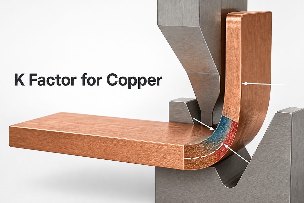
For bending, copper K-factor is the neutral-axis distance from the inside bend surface divided by material thickness. If the neutral axis sits 0.4 mm from the inside surface of a 1.0 mm sheet, K equals 0.40.
The metal inside a bend compresses while the outside stretches. Between those zones is a layer that keeps nearly the same length: the neutral axis. Its position determines how much material the bend consumes in the flat pattern.
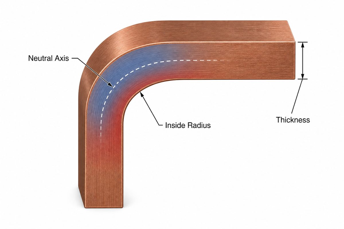
A higher bending K places the neutral axis farther from the inside surface and increases bend allowance. A lower K moves it inward and shortens the allowance. This value is dimensionless; it is not copper resistivity and it is not thermal conductivity.
| Meaning of K | Typical unit | Primary use |
|---|---|---|
| Bending K-factor | None | Flat patterns and bend allowance |
| Electrical K value | ohm-cmil/ft | Conductor voltage drop |
| Thermal conductivity, k | W/m·K | Heat-transfer analysis |
What K Factor Should You Use for Copper Bending?
Use 0.35, 0.407, and 0.452 as practical starting values for soft, half-hard, and hard copper respectively, then validate the selected value with the actual material and forming setup. A generic CAD default such as 0.44 may be convenient, but it can shift holes, slots, and terminals when the bend is tight or the copper temper changes.
| Copper condition | Starting K-factor | Use note |
|---|---|---|
| Soft or annealed copper | 0.350 | Confirm tight bends for thinning or surface cracking |
| Half-hard copper | 0.407 | Common initial value for formed copper parts |
| Hard copper | 0.452 | Use a suitable radius and verify springback |
The table does not replace a bend database. The production value belongs to a defined combination of copper grade, temper, thickness, bend direction, inside radius, tool, and process. If any of those inputs changes, repeat the trial or use a proven setup record.
K Factor for Copper Sheet Metal
The k factor for copper sheet metal controls the developed blank dimensions before a copper cover, shield, contact, or formed terminal is cut. Start with a temper-based value, use the drawing’s actual inside radius, and keep the same dimensioning convention throughout the calculation.
Copper sheet is more sensitive than a generic CAD material label suggests. Annealed sheet can flow around a tighter radius, while harder sheet usually needs a larger radius and shows more springback. Rolled sheet is also directional. A bend across the rolling direction often behaves differently from a bend parallel to it.
Before releasing a flat pattern, define:
- alloy or copper grade and temper;
- finished thickness and applicable thickness tolerance;
- inside bend radius and included angle;
- bend direction relative to the grain;
- tooling method, such as air bending, bottoming, or forming;
- critical hole-to-bend and terminal dimensions.
Do not use K-factor to hide an unsafe radius. K adjusts developed length; it does not prevent cracking. If a radius is below the material and temper limit, revise the geometry or forming process.
K Factor for Copper Busbar
The k factor for copper busbar should be selected by temper, thickness, radius-to-thickness ratio, and bend orientation, then proven on the intended machine. Busbar errors are costly because a few millimeters of flat-length error can misalign terminals, preload a bolted joint, or reduce designed clearance.
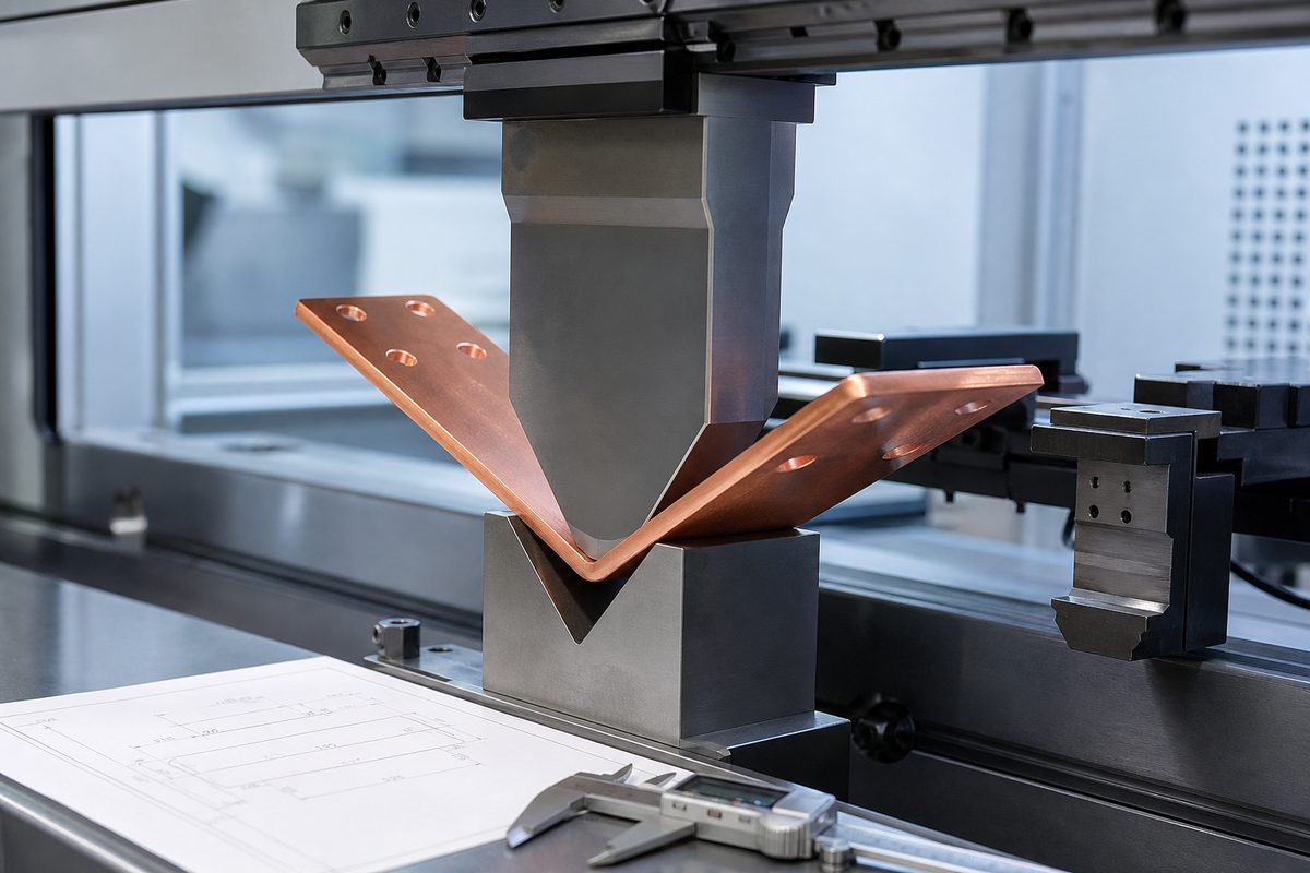
Flatwise bends use the busbar’s smaller dimension as the bending thickness. Edgewise bends deform the wide dimension and normally require different tooling, a much larger radius, and separate validation. The same equation may describe both, but the mechanical limits are not interchangeable.
Keep bend geometry separate from current capacity. The K-factor and bend allowance determine cut length. Cross-sectional area, temperature rise, enclosure conditions, joint design, and allowable loss determine ampacity. Our guides to copper busbar ampacity and copper busbar PCB construction address those electrical and structural decisions separately.
How Do You Calculate Bend Allowance for Copper?
Calculate copper bend allowance with BA = θ × (R + K × T), where θ is the bend angle in radians, R is the inside radius, K is the bending K-factor, and T is material thickness.
For a 90-degree bend, θ equals π/2, or about 1.5708. Consider a 2.0 mm half-hard copper sheet with a 2.0 mm inside radius and K = 0.407:
BA = 1.5708 × (2.0 + 0.407 × 2.0) = 4.42 mm
If the two straight legs are measured to the tangent points and are 30 mm and 45 mm, the developed length is:
30 + 4.42 + 45 = 79.42 mm
For several bends, calculate each allowance separately. Do not assume that every bend uses one K or radius. Add the straight tangent-to-tangent segments and all allowances, then round once at the final drawing precision.
Bend deduction is an alternative when the drawing uses outside dimensions. Either method can work, but mixing outside dimensions, tangent dimensions, and centerline dimensions in one calculation will not.
How Can You Find the Actual K Factor From a Test Bend?
Find the production K-factor by bending a measured coupon, measuring the resulting geometry, calculating the bend allowance consumed, and solving the bend equation for K. This is more reliable than copying a general table when the finished dimensions are critical.
- Cut a coupon from the production material batch and record its flat length and thickness.
- Bend it with the planned punch, die, direction, angle, and forming method.
- Measure the inside radius, final angle, and straight tangent lengths after springback.
- Calculate bend allowance: flat length minus the two tangent-to-end straight lengths.
- Solve K = (BA/θ − R) / T.
- Repeat the bend to confirm that the result is stable, then store it with the complete setup record.
Use calibrated measurement methods. An assumed inside radius can corrupt the result even when the flat length is measured accurately. For recurring production, maintain a bend table by material, thickness, radius, and tool instead of relying on a single copper value.
Which Variables Change the Copper K Factor?
Copper K-factor changes when material behavior or the deformation path changes. The largest practical drivers are temper, radius-to-thickness ratio, bend direction, tool geometry, and forming method.
- Temper: softer copper yields more readily; harder copper generally needs more radius and springback control.
- R/T ratio: changing the inside radius relative to thickness changes strain distribution and the neutral-axis position.
- Grain direction: rolling direction affects cracking risk and repeatability, especially on tight bends.
- Tooling: punch nose, die opening, tool wear, and alignment affect the actual radius and angle.
- Forming method: air bending, bottoming, wiping, and dedicated forming tools do not produce identical results.
- Part geometry: nearby holes, slots, embosses, plated areas, or width transitions can redistribute strain.
Springback changes the final angle rather than the theoretical neutral-axis location alone, but it must be calibrated with K because both affect the finished coordinates. A correct blank with the wrong recovered angle still fails to fit.
What Is the K Factor for Copper Wire?
For voltage-drop calculations, the k factor for copper wire is commonly taken as 12.9 ohm-cmil/ft at 75°C in the referenced conductor-resistance convention. This K is not the dimensionless bending value.

A common single-phase estimate is VD = 2 × K × I × L / CM. I is current in amperes, L is one-way length in feet, and CM is conductor area in circular mils. For a three-phase circuit, use 1.732 in place of 2.
For example, a 40 A single-phase load on 100 ft one-way copper conductors with 41,740 circular mils gives:
VD = 2 × 12.9 × 40 × 100 / 41,740 ≈ 2.47 V
This is an estimate. Conductor temperature, AC impedance, power factor, terminations, and installation conditions can change real voltage drop. Cable selection must also satisfy ampacity, protection, temperature rating, and applicable code requirements.
How Do Bending K Factor, Electrical K Value, and Thermal Conductivity Differ?
They differ in physical meaning, units, and formula. Use the equation’s units as a quick check before inserting a copper value.
| Property | Typical copper reference | Used to calculate |
|---|---|---|
| Bending K-factor | About 0.35–0.452 as temper-based starting values | Bend allowance and flat length |
| Electrical K value | 12.9 ohm-cmil/ft at 75°C | Conductor voltage drop |
| Thermal conductivity, k | Material- and temperature-dependent, in W/m·K | Heat flow and thermal resistance |
Do not paste 12.9 into a CAD bend table, and do not use 0.407 in a voltage-drop equation. Thermal conductivity is another separate material property; it belongs in a thermal model, not in either of these K-factor formulas.
What Errors Cause Wrong Copper Flat Patterns?
Wrong copper flat patterns usually come from an incorrect radius, the wrong dimensioning convention, or an unverified default K-factor rather than difficult arithmetic.
- Using one generic K for every copper temper: the neutral-axis location and springback do not remain constant.
- Using nominal instead of formed radius: the tool and process determine the actual inside radius.
- Measuring legs to bend centers: bend allowance calculations normally need tangent-point lengths.
- Combining allowance and deduction: choose the method that matches the drawing dimensions.
- Ignoring grain and edge condition: a mathematically correct flat can still crack during forming.
- Rounding each bend: small rounding errors accumulate across multi-bend copper parts.
- Releasing holes too close to the bend: deformation can oval holes or move terminal features.
For production, connect the flat-pattern calculation to the actual copper busbar manufacturing process. A drawing should identify the datum, radius, angle, finished critical dimensions, material condition, and inspection method.
FAQ About K Factor for Copper
Is 0.44 always the correct K factor for copper bending?
No. A value near 0.44 may be a CAD default or a useful starting point for some setups, but copper temper, radius, thickness, tooling, and bend direction can require a different value.
What is the best starting K factor for soft copper?
Start around 0.35 for soft or annealed copper, then verify it on a coupon made with the intended radius and tooling.
Can one copper busbar use several K-factors?
Yes. If bends use different radii, orientations, or processes, calculate and validate them separately rather than assigning one K to the entire part.
Does copper thickness change K-factor?
Thickness affects the radius-to-thickness ratio and the strain path. A K value proven for one thickness should not be assumed valid for another without checking.
What is the difference between K-factor and bend deduction?
K-factor locates the neutral axis. Bend deduction is a dimensional amount subtracted from outside flange dimensions to obtain flat length. K is one input used to calculate bend allowance and deduction.
Is the K factor for copper and aluminum the same?
No. In both bending and voltage-drop work, copper and aluminum have different material properties. Use values and validation data for the specified material rather than substituting one for the other.
Is the K factor for copper cable different from copper wire?
In a voltage-drop equation, the same copper resistivity convention can apply, but cable construction and installation affect temperature, AC impedance, and allowable ampacity. Those conditions still need separate checks.
Does XLPE insulation change copper’s electrical K value?
XLPE does not change copper’s intrinsic resistivity, but its temperature rating and installation conditions influence conductor operating temperature, which changes resistance and voltage drop.
Can thermal conductivity be called the K value for copper?
It is often written as lowercase k, but it is measured in W/m·K and describes heat transfer. It is unrelated to the dimensionless sheet-metal bending K-factor.
When should a test bend be mandatory?
Use a test bend when terminal position is critical, material or tooling has changed, the bend is tight, the copper is hard, or a repeated part is moving from prototype to production.
How Can EBest Circuit Support Copper-Intensive PCB and Busbar Projects?
At EBest Circuit, we help engineering and procurement teams coordinate copper-intensive PCB and PCBA requirements with the mechanical and electrical interfaces around the board. That may include heavy copper PCB requirements, current paths, mounting features, busbar connection points, and assembly fit.
For a useful review, send us the Gerber files, stackup or copper-weight requirement, fabrication drawing, BOM, quantity, and any busbar or formed-copper drawing that controls the interface. If the design includes critical bends, include copper grade, temper, thickness, radius, angle, finished dimensions, and the proven bend table where available. You can also review our heavy copper PCB capabilities before submitting the package.
If you are unsure which k factor for copper belongs in the drawing, tell us whether the task is flat-pattern development, voltage-drop estimation, or thermal analysis. Email the project files and questions to sales@bestpcbs.com for review and quotation.