When discussing Automotive MCPCB temperature range, engineers are not just referring to a simple specification window. This range—typically from -40°C to 150°C—represents a carefully engineered balance between material stability, thermal conductivity, electrical reliability, and long-term durability under harsh automotive conditions. From LED headlights to power control modules, MCPCBs (Metal Core Printed Circuit Boards) have become the backbone of thermal management in modern vehicles.
This article takes a practical, engineering-driven look at how MCPCBs operate across this wide temperature spectrum, what design considerations truly matter, and how to ensure consistent performance in demanding automotive environments.
What Does Automotive MCPCB Temperature Range Really Mean?
The Automotive MCPCB temperature range defines the safe operating limits within which the board can function without degradation in electrical or mechanical performance. In automotive electronics, this range is commonly specified as:
- Low temperature limit: -40°C
- High temperature limit: 125°C to 150°C (depending on design and materials)
This range aligns with automotive standards such as AEC-Q100 and ISO 16750, which simulate real-world conditions including cold starts, engine heat exposure, and environmental stress.
Unlike standard FR4 boards, MCPCBs are designed with a metal base layer, typically aluminum or copper, which significantly improves heat dissipation. This allows them to maintain stable operation even when ambient and junction temperatures rise.
Why Is -40°C to 150°C Critical in Automotive Applications?
Automotive systems operate in environments far more aggressive than consumer electronics. Temperature fluctuations are not gradual—they can be abrupt and extreme.
Key real-world scenarios include:
- Cold starts in winter climates (below -30°C)
- Engine compartment heat exposure (above 120°C)
- Thermal cycling during daily operation
- Heat accumulation in enclosed lighting systems
A properly designed MCPCB must handle all of these without:
- Cracking of dielectric layers
- Delamination between layers
- Solder joint fatigue
- Electrical drift
This is why the Automotive MCPCB temperature range is not just a design target—it is a reliability requirement.
How Does MCPCB Structure Support Wide Temperature Ranges?
MCPCBs achieve their thermal resilience through a multi-layer structure engineered for heat flow and mechanical stability.
Typical MCPCB stack-up includes:
- Copper circuit layer (conductive traces)
- Dielectric layer (thermally conductive, electrically insulating)
- Metal base (aluminum or copper)
Key material properties that matter:
- Thermal conductivity: 1.0–3.0 W/m·K (standard) or higher for advanced designs
- Dielectric breakdown voltage
- Coefficient of Thermal Expansion (CTE) matching
- High Tg (glass transition temperature) performance
The metal base acts as a heat spreader, quickly transferring heat away from hotspots such as LEDs or power components. This minimizes thermal gradients, which are often the root cause of mechanical stress.
What Happens at Low Temperatures (-40°C)?
Low-temperature performance is often underestimated, but it plays a critical role in automotive reliability.
At temperatures approaching -40°C:
- Materials contract, increasing mechanical stress
- Solder joints become more brittle
- Dielectric layers may lose flexibility
- Contact resistance can change slightly
A well-designed MCPCB compensates for these effects by:
- Using materials with matched CTE values
- Selecting flexible yet stable dielectric layers
- Ensuring robust solder joint design
This ensures that the circuit remains functional during cold starts, especially in regions with extreme winter conditions.
What Happens at High Temperatures (Up to 150°C)?
High temperatures introduce a different set of challenges, primarily related to thermal aging and material degradation.
At elevated temperatures:
- Dielectric materials may soften or degrade
- Copper oxidation rates increase
- Solder joints experience creep and fatigue
- Electrical insulation resistance may decrease
To maintain performance within the Automotive MCPCB temperature range, manufacturers typically use:
- High thermal conductivity dielectric materials
- Oxidation-resistant surface finishes (ENIG, OSP, etc.)
- High-temperature solder alloys
- Enhanced bonding techniques between layers
In LED applications, for example, maintaining junction temperature is critical. Even a small reduction in heat dissipation efficiency can significantly shorten LED lifespan.
How Does Thermal Cycling Affect MCPCB Reliability?
Thermal cycling—repeated heating and cooling—is one of the most demanding stress factors for automotive electronics.
A typical cycle might look like:
- Start at -40°C
- Heat up to 125°C or higher during operation
- Cool down again when the vehicle is off
This repeated expansion and contraction can lead to:
- Micro-cracks in dielectric layers
- Solder joint fatigue
- Delamination between layers
To address this, high-quality MCPCBs undergo:
- Thermal cycling tests (hundreds to thousands of cycles)
- Accelerated life testing
- Cross-section analysis for structural integrity
Designing for the full Automotive MCPCB temperature range means planning for long-term durability, not just initial functionality.
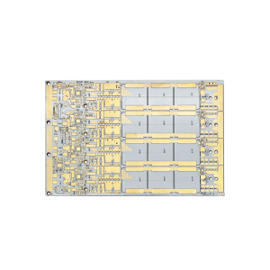
Which Automotive Applications Require This Temperature Range?
MCPCBs are widely used in automotive systems where heat management is critical.
Typical applications include:
- LED headlights and tail lights
- Daytime running lights (DRL)
- Engine control units (ECU)
- Power modules (IGBT, MOSFET-based systems)
- Battery management systems (BMS) in EVs
- On-board chargers and DC-DC converters
Each of these applications has unique thermal profiles, but all demand reliable operation across the full Automotive MCPCB temperature range.
How to Design MCPCB for -40°C to 150°C Operation?
Designing for this temperature range requires a multi-disciplinary approach combining materials science, thermal engineering, and PCB layout optimization.
Key design strategies:
- Optimize copper thickness for current and heat spreading
- Use high-performance dielectric materials
- Minimize thermal resistance between components and metal base
- Ensure proper heat sinking and mechanical mounting
- Design for uniform heat distribution
Layout considerations:
- Avoid sharp thermal gradients
- Place heat-generating components strategically
- Use thermal vias where applicable (in hybrid designs)
A well-optimized design ensures that the MCPCB operates comfortably within its thermal limits, even under peak load conditions.
Material Selection: Aluminum vs Copper Core
The choice of base material significantly affects performance within the Automotive MCPCB temperature range.
| Material Type | Thermal Conductivity | Weight | Cost | Typical Use |
|---|---|---|---|---|
| Aluminum Core | Moderate | Light | Lower | LED lighting, general automotive |
| Copper Core | High | Heavy | Higher | Power electronics, high-current systems |
Aluminum is widely used due to its balance of cost and performance, while copper is preferred for high-power applications requiring superior heat dissipation.
How Does MCPCB Compare to FR4 in Temperature Performance?
Traditional FR4 boards struggle in high-temperature environments due to limited thermal conductivity.
Comparison:
| Feature | MCPCB | FR4 PCB |
|---|---|---|
| Thermal conductivity | High | Low |
| Heat dissipation | Excellent | Limited |
| Max operating temp | Up to 150°C+ | Typically <130°C |
| Reliability in automotive | High | Moderate |
This is why MCPCBs are the preferred choice for thermal-critical automotive applications.
Common Challenges in Automotive MCPCB Design
Even with advanced materials, certain challenges require careful attention.
Typical issues include:
- Delamination under thermal stress
- Insufficient thermal conductivity
- Poor solder joint reliability
- Inadequate heat sinking
Addressing these early in the design phase significantly improves long-term performance.
Why Choose a Reliable MCPCB Manufacturer?
Achieving stable performance across the full Automotive MCPCB temperature range depends heavily on manufacturing quality.
A capable manufacturer should offer:
- Material traceability
- Thermal simulation support
- DFM (Design for Manufacturability) analysis
- Advanced testing (thermal cycling, X-ray, AOI)
- Automotive certifications (IATF 16949)
For example, providers like Best Technology integrate PCB fabrication, material sourcing, and assembly into one workflow, ensuring tighter process control and faster turnaround.
In closing, the Automotive MCPCB temperature range is not just a specification—it is a reflection of how well a design can withstand real-world stress. From freezing cold starts to high-temperature engine environments, MCPCBs provide a robust platform for reliable automotive electronics.
By selecting the right materials, optimizing thermal design, and working with experienced manufacturers, engineers can ensure consistent performance across the full -40°C to 150°C range. In modern automotive systems, that level of reliability is not optional—it is expected. If you are looking for a dependable partner for automotive MCPCB prototyping or volume production, EBest Circuit can support your project with fast feedback, engineering review, and reliable manufacturing service. Pls feel free to contact our team at sales@bestpcbs.com to discuss your design requirements and get a tailored solution for your automotive application.
FAQs About Automotive MCPCB Temperature Range
What is the typical Automotive MCPCB temperature range?
Most automotive MCPCBs operate between -40°C and 125°C or 150°C, depending on material selection and design requirements.
Can MCPCBs handle temperatures above 150°C?
Yes, but this requires specialized materials such as ceramic substrates or high-end dielectric systems, often used in extreme environments.
Why are MCPCBs better for automotive lighting?
They dissipate heat efficiently, which helps maintain LED brightness, color stability, and lifespan.
How long can an MCPCB last under thermal cycling?
With proper design and materials, MCPCBs can withstand thousands of thermal cycles, meeting automotive reliability standards.