PCB manufacturing PCB manufacturing
Home > Blog

inverter pcb

What Does an Inverter Do? DC-to-AC Conversion Explained
Thursday, July 23rd, 2026

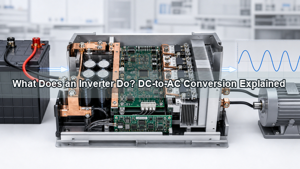
What does an inverter do? Its primary job is to convert direct current from a battery, solar array, fuel cell, or DC bus into alternating current with the voltage, frequency, and waveform required by the load. Modern inverters can also regulate motor speed, synchronize with the grid, manage battery power, monitor faults, and protect the connected system.
What does an inverter do DC to AC power conversion

What Does an Inverter Do?

An inverter reverses the function associated with a rectifier. A rectifier changes AC into DC, while an inverter synthesizes AC from a DC source. The output may be fixed at 120 V/60 Hz or 230 V/50 Hz, synchronized to a utility grid, or continuously adjusted to control the speed and torque of an AC motor.

The conversion is electronic rather than mechanical. Semiconductor switches repeatedly connect the DC source to the output in opposite polarities. Control electronics determine the switching sequence, while filters and magnetics shape the pulses into a usable AC waveform.

How Does an Inverter Work?

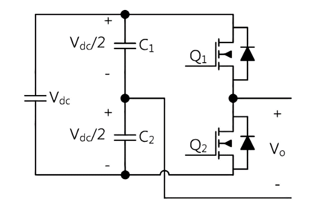
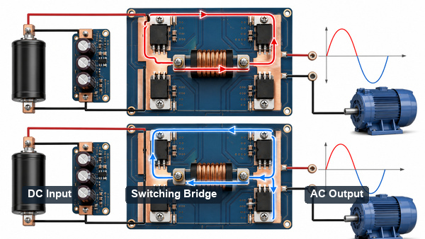
A basic full-bridge inverter uses four power switches arranged around the load. One diagonal pair conducts to apply positive voltage; the opposite pair conducts to apply negative voltage. Alternating between those states changes the direction of current and creates an AC output from a unidirectional DC input.

Practical units add a controller, gate drivers, current and voltage sensing, dead-time control, protection, and an output filter. The controller compares measured output with its target and changes the switching pattern to regulate amplitude, frequency, or motor torque.
How an inverter switches a DC bus into alternating current

What Parts Are Inside an Inverter?

The power path and control path have different electrical and layout requirements. The main functional blocks are:

  • DC input and protection: connectors, fuses, reverse-polarity control, surge suppression, and pre-charge circuitry.
  • DC-link stage: capacitors that supply pulse current and limit bus ripple.
  • Power bridge: MOSFETs, IGBTs, or SiC devices that switch the DC bus.
  • Gate drivers: circuits that deliver controlled drive current and isolation to the power switches.
  • Controller: MCU, DSP, or dedicated control IC that generates PWM and manages protection.
  • Sensing: current, bus-voltage, output-voltage, and temperature feedback.
  • Output network: inductors, capacitors, transformers, or motor windings that shape or use the switched waveform.

How Does PWM Create an AC Waveform?

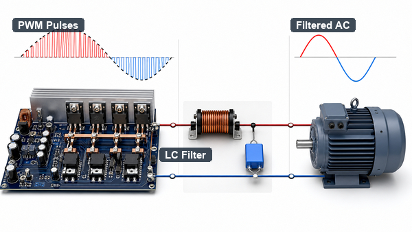
Pulse-width modulation changes how long each power switch remains on during every switching cycle. A sequence of narrow and wide pulses has an average value that follows a sine-wave reference. An LC filter or the inductance of a motor suppresses the high-frequency switching components, leaving the required low-frequency AC current.

Higher switching frequency can reduce filter size and improve waveform control, but it also increases switching loss, gate-drive demand, EMI, and PCB layout sensitivity. The final frequency is therefore a system trade-off involving semiconductor technology, power level, thermal limits, acoustic noise, and EMC targets.
PWM pulses filtered into an inverter sine wave output

What Output Waveforms Can an Inverter Produce?

Waveform Construction Typical behavior Design limitation
Square wave Direct polarity reversal Simple and inexpensive High harmonic content; unsuitable for many loads
Modified sine wave Stepped positive, zero, and negative levels Acceptable for some resistive loads Can increase motor heating, hum, and power-supply stress
Pure sine wave High-frequency PWM plus filtering Closest to utility AC and compatible with sensitive loads More control, filtering, and thermal complexity

Waveform labels alone do not define quality. Total harmonic distortion, regulation, transient response, common-mode noise, and load compatibility should also be checked.

What Types of Inverters Are Common?

Inverters can be classified by circuit topology or by system role. Voltage-source inverters operate from a relatively stiff DC-link voltage; current-source inverters control current through a DC-link inductor. Single-phase and three-phase bridges serve different loads, while isolated topologies add a transformer where safety, voltage conversion, or ground separation requires it.

System labels include string, central, micro, hybrid, grid-following, grid-forming, off-grid, motor-drive, and UPS inverters. These names describe installation and control behavior rather than one universal power stage.

Where Are Inverters Used?

Solar systems use inverters to convert panel DC into grid-compatible AC. Battery storage and UPS systems use them to supply AC during normal operation or an outage. EV traction inverters convert pack DC into controlled three-phase current for the motor and may reverse power flow during regenerative braking.

Motor drives vary output voltage and frequency to control pumps, fans, compressors, elevators, and factory equipment. Smaller inverter circuits appear in induction heating, microwave ovens, lighting ballasts, portable power stations, and other products that require controlled high-frequency or AC power.

For inverter, storage, and EV electronics, a new energy PCB must support the required current, isolation, thermal path, and control circuitry rather than being selected from application name alone.

How Efficient Is an Inverter?

Efficiency is output power divided by input power. Losses occur in semiconductor conduction, switching transitions, magnetics, capacitors, gate drivers, control circuits, and interconnects. Efficiency changes with input voltage, load, switching frequency, temperature, and power factor.

A unit rated at high peak efficiency may perform differently at light load or near its thermal limit. The loss calculation must use the intended operating point because every watt of loss becomes heat that the PCB, busbars, enclosure, and cooling system must remove.

What Is the Difference Between an Inverter and a Converter?

Inverter usually means DC-to-AC conversion. Converter is the broader term and may describe DC-to-DC, AC-to-DC, AC-to-AC, or DC-to-AC power conversion. A complete motor drive may contain an AC-to-DC rectifier, a DC link, and a DC-to-AC inverter in one enclosure.

A logic inverter is different again: it is a digital NOT gate that reverses a logic state, not a power stage designed to supply an AC load.

How Does PCB Design Affect Inverter Reliability?

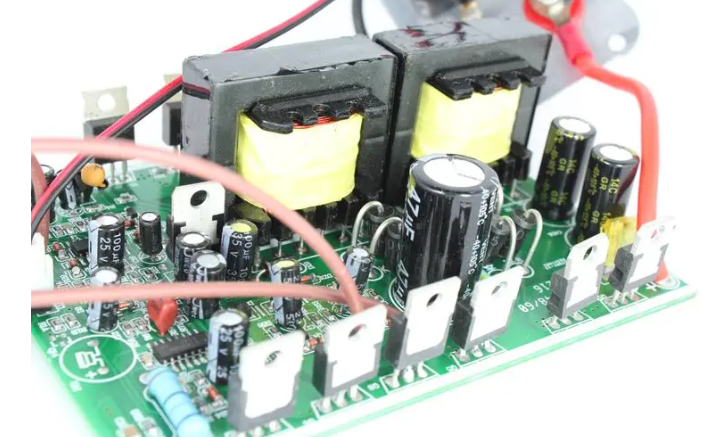
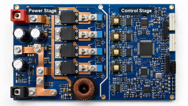
High-current loops should be short and wide, and the DC-link capacitor must sit close to the switching bridge to reduce parasitic inductance. Gate-drive loops need controlled return paths and separation from high dv/dt nodes. Creepage, clearance, isolation slots, copper thickness, via arrays, current sensing, and thermal interfaces must match the voltage and fault environment.
Inverter PCB power stage gate drive and control layout

A heavy copper PCB for power electronics can reduce conductor loss where current and board geometry justify it. Assembly must also control solder voiding, thermal-pad coverage, device coplanarity, press-fit or bolted connections, and insulation cleanliness. EBest Circuit (Best Technology) supports PCB fabrication and PCB assembly for power-electronics projects, including engineering review of stack-up, copper, thermal features, and assembly constraints.

FAQ About What an Inverter Does

What does a power inverter do?

A power inverter converts DC into AC at the voltage and frequency required by the connected load. Depending on the design, it may also regulate power, charge a battery, control a motor, or synchronize with the grid.

Can an inverter work without a battery?

Yes. A grid-tied solar inverter can operate from a photovoltaic DC source, and an industrial drive can operate from a rectified AC supply. Off-grid systems need a sufficiently stable DC source, which is often a battery.

How long will a 12 V battery last with an inverter?

Runtime depends on battery watt-hours, allowable depth of discharge, inverter efficiency, and load power. A first estimate is usable battery watt-hours multiplied by inverter efficiency, divided by load watts.

Does an inverter increase voltage?

Some designs include a transformer or DC-to-DC stage that raises voltage before or during inversion. Voltage increase is not automatic; it depends on topology and the required output.

Does an inverter use power when no load is connected?

Yes. Control electronics, gate drivers, sensing, fans, and magnetics create standby loss. Low-power sleep modes reduce this consumption in battery-operated systems.

Conclusion

What does an inverter do? It switches a DC source into a controlled AC waveform and, in advanced systems, also manages motors, batteries, grid interaction, monitoring, and protection. Reliable performance depends on the switching topology, control method, waveform, operating point, thermal design, and physical PCB current paths.

For inverter PCB fabrication or assembly support, contact EBest Circuit (Best Technology) at sales@bestpcbs.com.
You may also like

What is inverter PCB? Where is inverter p.c. board?
Wednesday, October 23rd, 2024

What is an inverter circuit board?

An inverter circuit board is designed to manage the conversion process by controlling the flow of current, regulating voltage, and ensuring efficient energy transfer. It can control and regulate the conversion of direct current (DC) into alternating current (AC). In the application of renewable energy systems such as solar power generation and wind power generation, inverters play a crucial role. It efficiently converts the DC energy collected by solar panels or wind turbines into AC power supplies suitable for home and business use.

An inverter PCB typically includes components such as power semiconductors (IGBTs or MOSFETs), microcontrollers, and various passive elements that enable the inverter to function correctly.

What is inverter PCB? Where is inverter p.c. board?

Types of Inverter PCB

Inverter PCBs come from several types, mainly are single-sided PCB, double-sided PCB and multilayer PCB.

Single-Sided PCB

A single-sided PCB is the most basic type, with all the components and circuits mounted on one side. It is commonly used in low-cost inverters with relatively simple circuits. Due to the limited space and circuit paths, its performance and power handling capabilities are moderate. Therefore, it is suitable for small-scale inverter systems or low-power home appliances.

Double-Sided PCB

Double-sided PCBs feature components and copper circuitry on both sides of the board. Furthermore, plated through holes can be drilled on such board to improve the electricity. These PCBs are suitable for mid-range inverter designs that require a higher number of components and connections, as they provide better performance and power efficiency. In higher power applications like motor control systems and renewable energy inverters, double sided PCB are commonly used.

Multilayer PCB

Inverters designed for industrial applications or high-performance devices often require multilayer PCBs. These boards consist of three or more layers of circuitry sandwiched between layers of insulation. Multilayer PCBs can reduce electromagnetic interference (EMI) and improve signal integrity, they are excellent in complex inverter systems used in electric vehicles (EVs), large solar arrays, and industrial motor drives.

What Benefits Does an Inverter PCB Offer?

First of all, ‌ high reliability ‌ is an important advantage of inverter PCB. Through precise circuit design and high-quality assembly processes, inverter PCBs can significantly improve the stability and reliability of equipment. In addition, the modular design makes troubleshooting and maintenance more convenient.

Secondly, ‌environmental protection ‌ is also an important feature of the inverter PCB. Conventional inverter PCBs may use halogen-containing chemical materials in the manufacturing process, which can pose potential threats to the environment and human health. The halogen-free inverter PCB adopts halogen-free substrate and lead-free welding technology, does not produce harmful environmental pollutants, and has less impact on the environment and human health.

In addition, ‌ easy to upgrade and maintain ‌is another important advantage of inverter PCBs. When the inverter needs to be upgraded or repaired, it can be achieved by replacing or repairing specific PCB modules, without large-scale changes to the entire system, which greatly reduces the complexity and cost of upgrading and maintenance.

Finally, ‌ highly integrated ‌ is also a significant advantage of inverter PCBs. Through a highly integrated design, the size and weight of the inverter are reduced for easy installation and maintenance.

What is an Inverter Circuit Diagram?

An inverter circuit diagram is a schematic representation that illustrates how the components on the PCB are interconnected to convert DC power into AC power. It provides a detailed view of the flow of current and the role each component plays within the inverter system.

What is inverter PCB? Where is inverter p.c. board?

The diagram typically includes:

  • Power Input: Showing where the DC power is supplied, often from batteries, solar panels, or other DC sources.
  • Switching Devices: Components like Insulated Gate Bipolar Transistors (IGBTs) or Metal-Oxide-Semiconductor Field-Effect Transistors (MOSFETs), which are used to alternate the direction of current, producing AC power.
  • Control Circuit: A microcontroller or other control logic that regulates the switching timing and frequency to generate a stable AC output.
  • Filters: Inductors and capacitors used to smooth out the AC waveform and minimize harmonic distortion.
  • Protection Circuits: Components that safeguard against overcurrent, overvoltage, and short circuits, ensuring safe operation of the inverter.

Applications of Inverter PCBs

Inverter PCBs are found in various applications, including renewable energy systems like solar inverters, uninterruptible power supplies (UPS), electric vehicle systems, motor drive systems, and home appliances like air conditioners, refrigerators, and washing machines. Below are the typical applications of inverter PCBs:

Solar Inverters

In solar power systems, inverter PCBs are critical for converting the DC electricity generated by solar panels into usable AC electricity for homes and businesses. Solar inverters also use MPPT (Maximum Power Point Tracking) algorithms to optimize energy harvesting.

Uninterruptible Power Supplies (UPS)

In UPS systems, inverter PCBs ensure the reliable conversion of DC battery power into AC electricity during power outages. These systems are vital in data centers, hospitals, and other environments where uninterrupted power is essential.

Electric Vehicles (EVs)

EVs rely on inverter PCBs to convert the DC power stored in the battery into AC power to drive the motor. The performance and efficiency of the inverter PCB directly affect the vehicle’s range and driving experience.

Industrial Motor Drives

Many industrial applications use AC motors for machinery and equipment. Inverter PCBs regulate the speed and torque of these motors by converting DC power into controlled AC output, they are important for automation, robotics, and manufacturing processes.

Home Appliances

Many modern home appliances, such as air conditioners, refrigerators, and washing machines, use inverter technology for energy efficiency. Inverter PCBs in these devices help control motor speed and reduce energy consumption, contributing to more eco-friendly and cost-effective home systems.

What Causes an Inverter Board to Fail?

There are many factors that can cause inverter board to fail, and some of them we can recognize by visual, but sometimes we cannot. Here we listing some potential factors that make inverter PCB be damaged or fail.

  • Overheating

Excessive heat is a common cause of inverter PCB failure, particularly in high-power applications. Poor thermal management or inadequate cooling can cause components to overheat and degrade over time. For such conditions, aluminum PCBs has good thermal conductivity, this can help to heat dissipation and transfer heat out efficiently, but if the cooling system is not properly designed, even these boards can fail.

  • Poor insulation

This may be due to poor installation, improper location selection and poor quality of equipment of PCB board. We can check whether the DC connector has short-circuit supports or burns due to water immersion, and whether the edges of the component become blackened.

  • Low bus voltage

If this problem occurs in the morning and evening, then it is normal as the inverter tries to limit the generation conditions. If it occurs during normal daytime hours, it can be detected by above method.

What is inverter PCB? Where is inverter p.c. board?
  • Abnormal current leakage

These problems are often caused by poor installation quality, improper location selection and poor equipment quality. We can locate the fault area and make it insulated. If the failure is caused by the material, then replace the incorrect one.

  • No response

Ensure that the DC input is correctly connected and the inverter has built-in reverse short circuit protection. After the connection is restored, the inverter can start. If the inverter still does not work, it may be the fault of the inverter oscillation circuit or inverter itself has a problem. Try to troubleshooting and repair with new one.

Considerations When Choosing the Right Inverter PCB

Several factors should be considered when choose an inverter PCB for your device. Let’s talk about them.

1. Power Rating

    Select a PCB that can handle the power levels required by the application. Overloading a PCB beyond its rated capacity can lead to overheating, component failure, or even dangerous situations like fire.

    2. Thermal Management

    In applications where heat generation is a concern, selecting a PCB with good heat dissipation is vital. Aluminum PCB or high-quality multilayer PCBs can help dissipate heat effectively. Consider heat sinks, design thermal vias, and adequate ventilation in your design to improve thermal performance.

    3. Component Quality

    From above, we know high quality components used in the PCB is important as well. High-quality capacitors, transistors, and diodes ensure reliable operation, even in harsh conditions. Always choose components rated for the expected load and environment, or get touch with EBest Circuit (Best Technology) to enjoy a one-stop service from components sourcing and PCB assembly.

    4. Environmental Resistance

    If the inverter will be used in outdoor or industrial environments, choose a PCB with protective coatings, such as conformal coatings, to shield against moisture, dust, and corrosive elements. Solar power systems or outdoor motor control applications must take it in mind.

    5. PCB Layout and Size

    The physical size and layout of the PCB should align with the space available in the inverter system. A well-organized PCB layout helps reduce electromagnetic interference (EMI) and improves overall efficiency.

    Above are all the information about inverter PCB that we can shared. If you have a question concerning the topics, please contact us.

    You may also like