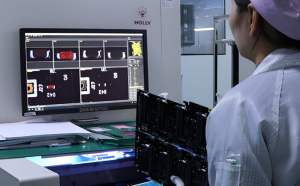
An infusion pump PCBA is the assembled circuit board that connects the pump’s processor, motor drive, power supply, sensors, alarms and user interface. It does not determine safe drug delivery by itself; reliability depends on the approved circuit design, controlled assembly, documented inspection, agreed board-level tests and final verification inside the complete pump. At EBest Circuit (Best Technology), we manufacture and assemble these boards to customer-controlled files while maintaining the material, process and test records specified for the project.
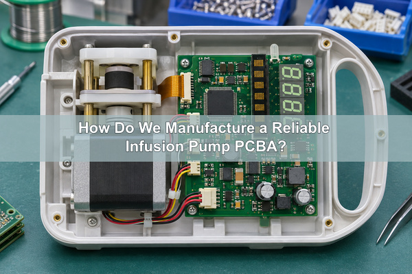
What Is an Infusion Pump PCBA?
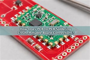
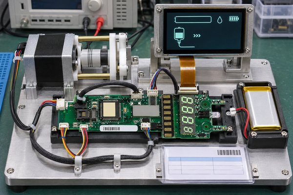
An infusion pump PCBA is a populated and soldered infusion pump circuit board. Depending on the device architecture, one board may combine the main controller, pump drive, sensor inputs, display and alarm circuits, or the functions may be divided among a control board, power board and interface board. The fabrication drawing defines the bare infusion pump PCB; the BOM, placement data, assembly drawing, firmware-loading instruction and test specification define the assembled board.
Our work begins with those approved manufacturing files. We can fabricate the PCB, source specified components, perform SMT and through-hole assembly, inspect solder joints and execute the tests agreed in the purchase package. The medical-device manufacturer remains responsible for the pump architecture, dosage algorithm, software, alarm strategy, risk management, regulatory submission and final device release.
What Functions Does the Infusion Pump PCBA Support?
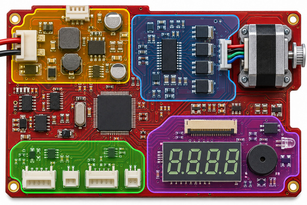
The board converts commands and sensor feedback into controlled electrical actions. A typical infusion pump control board may read flow, pressure, door, position or air-in-line sensors; drive a motor or actuator; manage mains and battery power; operate the display and keypad; and activate visual or audible alarms. The actual functions depend on the pump type and the customer’s system design.
| Functional block | PCBA responsibility | Design input we need |
|---|---|---|
| Main control | Process sensor inputs and issue drive, display and alarm commands | Approved schematic, processor, clock, memory and programming requirements |
| Pump drive | Switch motor current and return position or movement feedback | Motor type, voltage, current profile, connector and load condition |
| Sensor interface | Condition and digitize pressure, position, door, flow or air sensor signals | Sensor type, range, excitation, interface and fault-state definition |
| Power management | Regulate rails, charge or monitor the battery, and supervise power transitions | Input range, battery chemistry, rail limits, peak load and protection strategy |
| HMI and alarms | Connect display, keypad, indicators and audible alarm hardware | Display interface, keypad circuit, indicator loads and alarm-output requirements |
| Communications | Provide service, network or peripheral interfaces where specified | Protocol, isolation, connector, cable and EMC requirements |
How Do Pump Type and Use Environment Change the PCBA?
A syringe pump, volumetric pump, ambulatory pump and patient-controlled analgesia pump do not impose the same board requirements. A syringe mechanism may emphasize precise motor position and force feedback. A volumetric or peristaltic design may use different drive loads, door detection and pressure sensing. A battery-powered ambulatory pump places more weight on low-power operation, charging, mechanical size and repeated power transitions.
The intended use environment also changes the manufacturing package. Portable equipment may require stronger connector retention and more attention to shock and vibration. Equipment used near other medical electronics needs an EMC plan for the complete enclosure and cable set. Cleaning agents, humidity, storage temperature and expected service life can affect laminate, coating, connector and marking choices. These conditions should be stated in the design input rather than inferred from the phrase “medical PCBA.”
| Pump or environment | Board-level emphasis | Information to define before quotation |
|---|---|---|
| Syringe pump | Motor position, force or pressure feedback, compact drive path | Motor and sensor interfaces, peak current, connector cycling |
| Volumetric pump | Multiple sensors, door status, actuator control and alarm outputs | Sensor list, fault states, harness map and mechanical keepouts |
| Ambulatory pump | Battery operation, low-power states, small outline and impact resistance | Battery pack, charging architecture, enclosure constraints and duty cycle |
| PCA pump | User-input interface, event logging and alarm hardware defined by the device design | Keypad/display interfaces, memory, communications and access-control hardware |
| Hospital environment | EMC, cleaning exposure, serviceability and traceable configuration | Applicable device standards, cleaning agents, cable set and service plan |
Infusion Pump PCBA vs General Consumer PCBA
The circuit technologies may overlap, but the manufacturing controls are not automatically equivalent. A consumer board may be released with a standard assembly drawing and a basic functional check. An infusion pump project commonly needs tighter configuration control, clearer acceptance criteria, defined traceability and test records connected to the medical-device manufacturer’s risk controls. The exact requirements must still be written into the contract and quality package.
| Comparison item | Infusion pump PCBA | General consumer PCBA |
|---|---|---|
| Design ownership | Controlled by the medical-device manufacturer with device-level risk and verification requirements | Controlled by the product owner, often with lower documentation burden |
| Component changes | Substitutions normally require documented technical review and customer approval | Approved alternates may be managed with a broader purchasing rule |
| Traceability | May require work-order, material-lot, date-code, process and test linkage | Often limited to production lot or date code |
| Testing | Board tests are tied to specified functions and device risk controls | May use a standard electrical or functional screen |
| Final acceptance | Board acceptance plus complete-device verification and regulatory release | Product-owner acceptance based on the consumer product specification |
How Should Power and Battery Circuits Be Partitioned?
Power input, battery charging, motor drive and sensitive measurement circuits should not be treated as one undifferentiated copper area. The layout needs intentional current-return paths, sufficient copper for peak motor current, clearance around switching nodes and physical separation from low-level sensor inputs. Brownout supervision, reverse-polarity protection, overcurrent protection and battery switchover belong to the customer’s circuit design; manufacturing must preserve the specified creepage, copper geometry and component orientation.
During DFM review, we check whether copper weight, trace width, thermal relief, via structure and connector footprint are manufacturable. If a compact layout requires blind or buried vias, our HDI and special PCB capability can be reviewed against the actual stack-up. HDI should be selected because routing and interconnection require it, not simply because the device is small.
How Are Motor, Sensor and Alarm Circuits Integrated?
The motor path carries changing current, while pressure, position and other sensor paths may carry much smaller signals. Placement should keep high-current switching loops short and maintain the grounding and filtering shown in the approved design. Connector keying, polarity, retention and cable exit direction also matter because a correctly assembled board can still fail integration if a harness is reversed, strained or routed across the pump mechanism.
Alarm hardware needs a testable interface. The PCBA can be checked for buzzer drive, indicator outputs, display response and defined input-state recognition, but those checks do not prove that every device alarm is clinically adequate. The customer supplies the test limits and expected response for each simulated state; we build the fixture and test sequence only to the agreed scope.
How Do We Control Noise and EMC at Board Level?
Board-level EMC control starts with the approved stack-up, return paths, placement and filtering. Motor drivers, switching regulators, clocks and display interfaces can couple noise into sensor or communication circuits. Short current loops, continuous reference planes, controlled connector transitions, input filtering and appropriate separation reduce risk before the assembly reaches enclosure-level testing.
We can manufacture controlled-impedance structures and inspect the board against the supplied stack-up. Our published FR4 capability includes impedance control, with acceptance limits dependent on the specified impedance and coupon plan. However, a board test cannot establish compliance for the complete pump. Cables, enclosure, grounding, power adapter, firmware states and connected accessories must be present in the customer’s device-level EMC evaluation.
Detailed Infusion Pump PCBA Manufacturing Parameters
The following values describe our published PCB and assembly capability envelope for an infusion pump PCBA. They are feasibility references, not a recommended infusion pump specification, and individual maximum or minimum values cannot necessarily be combined in one build. We confirm the complete stack-up, package mix, board size, quantity, materials and test plan before accepting the production configuration.
| Manufacturing item | Published capability | Project confirmation required |
|---|---|---|
| FR4 layer count | Up to 32 layers | Finished thickness, stack-up, via type and material availability |
| Standard minimum line/space | 4/4 mil | Copper weight, local density, impedance and yield review |
| HDI minimum line/space | Down to 2/2 mil in the capability list | Specific HDI structure, copper, panel and engineering approval |
| Minimum finished hole | 0.20 mm standard; 0.10 mm HDI | Aspect ratio, plating, stack-up and hole type |
| Smallest listed SMD | 01005 | Pad design, stencil, package supply format and inspection plan |
| Minimum listed BGA pitch | 0.25 mm | Package drawing, pad geometry, X-ray criteria and rework policy |
| Assembly methods | SMT, THT and mixed assembly | Selective/wave/manual process, heat-sensitive parts and fixture needs |
| Component supply formats | Reel, cut tape, tube, tray and loose parts | Packaging condition, feeder suitability, quantity and traceability |
| Inspection options | 3D SPI, AOI and X-ray among available controls | Which packages and defects each inspection must cover |
For a conventional controller, our FR4 PCB manufacturing route may provide the required multilayer structure and controlled impedance. A capability value only shows what may be manufacturable; it does not establish the needed layer count, copper, hole size, package pitch or acceptance criterion for a particular pump.
How Do We Manufacture and Inspect an Infusion Pump PCBA?
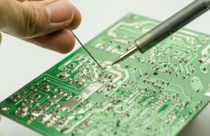
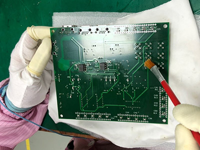
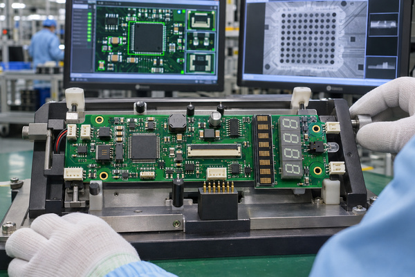
Our PCB assembly service converts the approved BOM, placement data, assembly drawing and process instructions into a controlled production route. The sequence can include incoming material verification, solder-paste printing, 3D SPI, SMT placement, reflow, AOI, X-ray for hidden joints, through-hole assembly, cleaning or drying where specified, functional testing and final inspection.
Each inspection has a defined job. SPI checks paste deposits before component placement. AOI evaluates visible placement and solder features after reflow. X-ray can examine hidden BGA or bottom-terminated joints. None of these tools alone proves electrical function, sensor accuracy or fluid-delivery performance. The control plan therefore matches each known failure mode to an inspection or test that can actually detect it.
How Is Component and Lot Traceability Maintained?
Traceability starts before placement. The purchase package should define whether records must link the finished serial or lot to the PCB lot, component manufacturer, manufacturer part number, supplier, date code, incoming status, work order, process route and test result. We source through manufacturers and recognized distributors where applicable, and we apply the approved AVL and substitution rules supplied for the project.
A substitution is not accepted merely because the package and nominal value match. For an infusion pump, tolerance, temperature behavior, lifetime, qualification status, firmware compatibility and supply-chain change control may matter. When a specified part is unavailable, we present the candidate and supporting data for customer review rather than silently changing the BOM.
What Testing Should Be Defined for Infusion Pump PCBA?
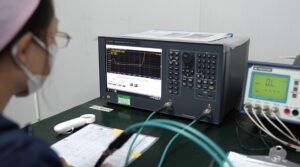
Testing should be derived from the board’s actual interfaces and failure risks. Bare-board electrical test checks continuity and isolation against the netlist. Assembly-level tests can confirm power rails, current consumption, programming, communications, motor outputs, sensor-input simulation, display response and alarm outputs. The customer defines limits, stimuli and pass/fail behavior; we confirm fixture feasibility and record format.
| Test or inspection | What it can confirm | What it cannot prove alone |
|---|---|---|
| Bare-board electrical test | Net continuity and isolation against supplied data | Component function or finished pump performance |
| SPI / AOI | Paste deposition and visible assembly conditions | Hidden electrical behavior or dosing accuracy |
| X-ray | Selected hidden solder-joint and void conditions | Software, sensor calibration or system reliability |
| Power-up test | Input current, rail voltages and basic protection behavior | All operating modes or battery endurance |
| Functional fixture test | Defined motor, sensor, display, communication and alarm interfaces | Complete fluid path, clinical workflow or device compliance |
| Device-level verification | Flow accuracy, alarms, EMC, battery operation and essential performance under the device plan | This remains the device manufacturer’s controlled validation activity |
How Do Prototypes Move into Repeat Production?
A prototype proves that the selected materials, footprints, assembly route and test access can be built, but repeat production also needs a stable configuration. Before transfer, unresolved DFM and DFA findings should be closed, the BOM and AVL frozen for the intended build, programming and test revisions controlled, workmanship criteria agreed and approved deviations linked to the affected lot.
For later orders, we compare the released revision, customer-supplied material status, component availability, process instructions and fixture version before production. Any approved change should identify the affected board revision and effective lot. This keeps an earlier prototype decision from becoming an undocumented production change.
Infusion Pump PCBA FAQs
Is an infusion pump controller the same as an infusion pump PCBA?
Not necessarily. The infusion pump controller may refer to the complete control function, including firmware, display, sensors, motor and enclosure interfaces. The PCBA is the physical assembled board that implements part or all of that controller.
Can you source components as well as assemble the board?
Yes. We support consigned, partial-turnkey and full-turnkey assembly. For component sourcing, identify approved manufacturers, alternates, date-code or traceability requirements and any parts that the customer will supply.
Does a passed PCBA functional test prove infusion accuracy?
No. A fixture can verify specified electrical interfaces and responses. Infusion accuracy depends on the complete mechanical fluid path, sensors, calibration, software, operating conditions and device-level verification.
Which documents should accompany production boards?
The required package is project-specific. It may include shipment traceability, material or conformity records, inspection summaries, programming versions and functional-test results. The customer should define the exact deliverables and retention period before production release.
What Should You Include in an Infusion Pump PCBA RFQ?
A useful RFQ defines the board, assembly, testing and documentation together. Gerber files alone cannot show component sourcing rules, programming, sensor simulation, fixture interfaces or the records required at shipment. Send the package early enough for us to identify missing design inputs before price and delivery are fixed.
| RFQ item | Information to provide | Why it affects quotation |
|---|---|---|
| PCB data | Gerber or ODB++, drill files, netlist, stack-up and fabrication drawing | Defines materials, geometry, test and board process |
| Assembly package | BOM, AVL, centroid data, assembly drawing and polarity notes | Defines sourcing, placement, feeders, tooling and inspection |
| Programming | Device list, files, version control and security procedure | Defines programming equipment, access and records |
| Test specification | Inputs, loads, limits, pass/fail logic, connector pinout and output record | Defines fixture, software, cycle time and validation responsibility |
| Quality records | Traceability depth, certificates, inspection data and retention period | Defines data capture and shipment documentation |
| Commercial inputs | Prototype and production quantities, forecast, consigned parts and delivery target | Defines material purchase, panelization, capacity and lead time |
Send the controlled package to sales@bestpcbs.com. We will review the infusion pump PCB assembly, identify missing manufacturing or test inputs, and confirm the applicable PCB, component-sourcing, assembly, inspection and documentation scope before quotation.