SMT splice tape joins the end of one component carrier tape to the start of another so a placement-machine feeder can keep advancing parts. A usable splice must preserve the carrier’s tracking through the feeder and the cover tape’s peel path; adhesive alone cannot correct misaligned pockets or a missing component at the join. In PCB assembly, the purpose is to continue placement without treating two reels of different parts as interchangeable.

At EBest Circuit (Best Technology), our PCB assembly service accepts components supplied on reels as part of SMT projects. Reel identity, feeder setup and placement checks matter more to the finished board than whether a join looks neat from above. The correct splice method depends on the component packaging and the feeder selected for the job.
What Is SMT Splice Tape?
SMT splice tape is an adhesive joining material used at the meeting point of two reels of carrier tape. Depending on the system, it may bridge the cover tape, reinforce the carrier connection, or work with a metal clip that gives the carrier its mechanical join. A cover-tape extender is different: it adds a leader to the beginning of a reel rather than joining two populated reels.
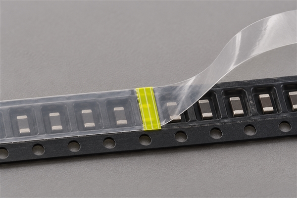
Look at the two paths separately. The carrier, including its sprocket holes and pockets, must pass through the feeder without a step or twist. The cover tape must peel continuously so parts become accessible at the pick position. A strip that holds the top film but leaves the carrier ends free is not a complete reel-to-reel splice.
Why Are Component Reels Spliced During SMT Assembly?
Reels are spliced to avoid stopping a placement run each time a feeder approaches the end of a reel. The next reel is prepared while the current reel is still feeding, then the two tapes are joined before the last usable pockets pass the pick point. This is especially useful when a high-use component would otherwise interrupt repeated boards.
Continuity has a limit: the new reel must be an approved source for the same BOM line, with the right part, package, orientation and moisture-handling state. A mechanically sound join cannot make a wrong component acceptable. If the replacement reel is an approved alternate rather than the same manufacturer part number, the alternate approval and machine setup need to be resolved before the transition.
Which Parts of the Carrier Tape Must Line Up?
The two carrier ends need matching width, sprocket-hole alignment, pocket orientation and a smooth transition through the feeder guides. At the cut, no loose pocket fragment should remain where it can snag the mechanism or release a part. The cover tape needs its own continuous peel path; it should not fold adhesive into the pickup window.
Carrier width is only a first filter. For example, a published 8 mm component-tape drawing specifies a 4.0 mm sprocket-hole pitch and 4.0 mm pocket pitch, whereas a published 12 mm example has a 4.00 mm sprocket pitch but 8.00 mm pocket pitch. These are different named packaging examples, not universal dimensions for all 8 mm or 12 mm reels. Read the actual component packing drawing before deciding where to cut and where the next pick should occur.
How Do You Choose Splice Tape for an 8 mm or 12 mm Reel?
Choose the splice product for the actual carrier width and construction, then check whether its system requires a clip, a single-sided strip, a double-sided strip or a separate cover-tape join. An 8 mm label on the reel does not mean every 8 mm splice product fits every feeder. Paper and embossed-plastic carriers can also need different handling at the cut and crimp.
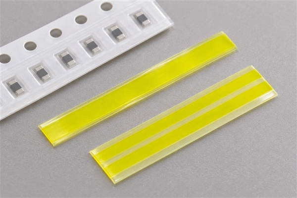
The table below gives one manufacturer’s published single-splice tape examples. The strip dimensions are product dimensions, not carrier tolerances or our production specifications. They show why the splice strip is narrower than the carrier and why a 12 mm reel is not automatically served by an 8 mm strip.
| Carrier | Item | Strip size |
|---|---|---|
| 8 mm | SR.0208.0 | 4.5 × 48 mm |
| 12 mm | SR.0212.0 | 7 × 48 mm |
| 16 mm | SR.0216.0 | 9.5 × 48 mm |
| 24 mm | SR.0224.0 | 17 × 48 mm |
These published dimensions come from the Methods Automation Splice-Rite product brochure. Before use, match the current item revision to the carrier and tool. A 4.5 mm strip intended for an 8 mm carrier does not justify covering a sprocket hole or relying on the strip alone when that system calls for a mechanical clip.
How Do You Splice Two SMT Carrier Tapes?
Start by confirming the replacement reel’s part number and feed orientation. Then cut the outgoing and incoming carriers at an approved position between pockets, align their sprocket holes in the matching splice tool, and form the specified mechanical join. Finish the cover-tape connection without obstructing the peel path.
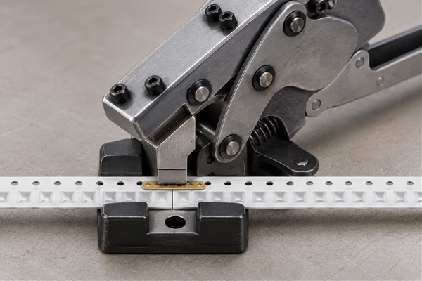
- Prepare: Identify both reels, check pocket direction and verify the replacement against the approved BOM.
- Cut and align: Trim both tapes between complete pockets; place the sprocket holes on the tool’s guides and keep the carrier edges flush.
- Join: Crimp the correct clip or shim if the system requires one, then apply the matching splice strip and cover-tape joint.
- Feed and verify: Advance the join through the feeder under the approved setup and inspect the first accessible pockets and picks.
A manual splice-tool data sheet describes locking clamps and guide pins for holding the two tapes during a shim or tape-and-shim join. That explains the sequence but not a universal force setting or acceptance limit. The exact cutting point, tooling and test advance should follow the actual feeder and splice-material instructions.
What Can Go Wrong at the Cover-Tape Join?
A cover tape that separates too early can expose parts before the pickup point. One that catches or peels unevenly can delay exposure and produce an empty or rotated pickup. Excess adhesive over a pocket can hold a component down or transfer residue into the feeder. These are different failure modes, so a single visual check of the carrier seam is not enough.
| Symptom | Path | First check |
|---|---|---|
| Film lifts early | Cover tape | Leader and overlap |
| Feeder stops | Carrier | Clip and hole alignment |
| First pick is empty | Cut and first full pocket | |
| Part sticks | Cover tape | Adhesive and peel |
Observe where the trouble begins before replacing material at random. A jam at the guide points to carrier geometry; a missed pick with smooth carrier travel points toward the pocket or cover-tape path. Once the feeder has been corrected, inspect the affected boards against the placement data rather than assuming all boards before the alarm are good.
How Do Feeder Sensors Affect Splice Selection?
Some feeders use splice detection or tracking features, but their sensing method is machine-specific. A splice product marketed as sensor-compatible is not proof that a particular feeder will recognize it. Match the tape system to the feeder model and the supplier’s compatibility instructions, then check the response during setup.
The important test is the transition itself: the feeder should advance the join, keep the part pockets registered and return the expected pick information. If the machine does not detect the splice, an operator may need a controlled reel-change procedure. Do not assume that a colored strip alone provides an electronic identity check or prevents the wrong reel from being loaded.
When Is a Reel Change Safer Than a Splice?
Stop and change the reel when a correct join cannot be made or verified for that carrier and feeder. Examples include damaged pockets near the end, an incompatible carrier format, an unavailable approved splice method, or uncertain part identity. An unqualified repair is not preferable merely because it avoids a short stoppage.
Also separate packaging continuity from material control. A new reel with a different lot, date code or approved alternate may require a recorded transition even if the physical splice feeds perfectly. The production instruction and customer traceability requirement determine whether the two lots may run consecutively and how the change is recorded.
How Should the First Picks After a Splice Be Checked?
After the join reaches the feeder, confirm that it advances without snagging, that the cover tape opens at the intended point and that the first populated pockets yield correct picks. The first few placements after the transition deserve attention because a seam can alter the pickup timing or expose an empty pocket. A normal machine alarm response is useful, but it is not the whole verification.
Suppose the approved packing drawing specifies 4 mm sprocket-hole pitch but 8 mm pocket pitch. Two sprocket intervals correspond to one pocket. At the splice, check the pocket sequence against that drawing before using the first machine pick as evidence of a good join; a correctly aligned hole row can still leave the pickup position over an empty transition pocket.
For a board-level check, compare the affected reference designators with placement records and the planned part identity. Automated optical inspection may find missing or misaligned components after placement or soldering; it does not by itself prove the two reel labels were correct. Where lot-level traceability is specified, link the reel transition to the production record as well as the visible placement result.
What Reel-Change Information Should Be Recorded?
A useful record connects the old reel, new reel, feeder location and production point. It should preserve the manufacturer part number and lot/date-code information when the project requires those fields. Recording only “tape replaced” leaves no way to reconstruct which boards used which reel.
- Material: full part number, approved alternate status, reel or lot identifiers.
- Machine: line, feeder position and applicable setup revision.
- Transition: time or board/serial boundary, operator or system event, and first-pick verification result.
- Exception: any rejected pocket, jam, mispick or affected-board disposition.
The required depth depends on the customer’s traceability agreement. In a consigned-material build, provide reel labels and the approved BOM so the incoming material check can tie the physical reels to the assembly data. Our published PCB assembly service includes component incoming checks; project-specific splice and traceability records should be specified before production.
How Does a Bad Splice Affect PCB Assembly Quality?
A failed splice can cause a feeder stop, missing placement, wrong rotation, or a wrong-part transition. These are assembly defects, not defects in the adhesive strip alone. The impact depends on whether the machine catches the event and how many boards pass before the affected placements are isolated.
Follow the fault to the board. If the feeder loses registration, identify the first potentially affected board, inspect the relevant component positions and decide whether rework or additional testing is needed. Do not use a pass from unrelated checks as proof that the BOM part and placement are correct. Prevention is the combination of approved reels, a qualified splice method, feeder setup and transition verification.
As a hypothetical traceability example, if the last confirmed correct pick was recorded on board 120 and a feeder alarm followed board 126, hold boards 121–126 until the placement record and the affected reference designators have been checked. The actual boundary must come from the machine and board records, not from a fixed six-board rule. If those records cannot establish the boundary, widen the hold to the last defensible checkpoint.
What Should You Send With Consigned SMT Reels?
Send the approved BOM with complete manufacturer part numbers, revision-controlled assembly and placement files, and reel labels that identify the supplied material. State any lot-separation or substitution restrictions. These inputs let the assembly team verify that a replacement reel belongs at the same feeder position before the carrier tapes meet.
For an EBest Circuit PCB assembly inquiry, also identify cut tape versus full reels, any special handling state and the quantity planned per build. That information helps us review incoming parts and the production route. It does not imply that every reel will be spliced or that we sell a particular splice-tape brand.
What Are the Detailed SMT Splice Tape and Carrier Tape Parameters?
The useful parameters are not a single “splice width.” Carrier width, sprocket pitch, pocket pitch, carrier material, cover-tape construction and the selected splice system all affect whether a join will feed. The values below are sourced examples from named supplier drawings; they are not a universal acceptance specification or an EBest Circuit capability table.
| Metric | Epson FA-128 8 mm | Avago OR12 12 mm |
|---|---|---|
| Carrier width | 8.0 ± 0.2 mm | 12.0 ± 0.3 mm |
| Hole pitch | 4.0 ± 0.1 mm | 4.00 mm |
| Pocket pitch | 4.0 ± 0.1 mm | 8.00 mm |
Consider the two example carrier drawings. Both specify a 4 mm sprocket-hole pitch, yet their pocket pitches differ: 4 mm versus 8 mm. Counting one sprocket step as one component would be wrong for the 12 mm example. The actionable check is to identify the actual packing drawing, choose a compatible joining material for its carrier width, cut between complete pockets and confirm the first populated pick after the splice.
SMT Splice Tape vs Full Reel Change: Which Is Appropriate?
A splice is appropriate when two approved reels have compatible packaging and the feeder, splice system and transition check can be controlled. A full reel change is appropriate when any of those conditions is missing. The choice is not simply “fast versus slow”: a failed continuous feed can consume more time and create an uncertain board boundary.
| Check | Splice | Change reel |
|---|---|---|
| Part identity | Approved and recorded | Approval unresolved |
| Carrier | Join is compatible | Damaged or incompatible |
| Feeder | Transition test passes | Join cannot be qualified |
| Board record | Boundary is traceable | Boundary is uncertain |
If the replacement reel is correct but the pocket transition cannot be shown to advance and pick reliably, stop the feeder and load the reel by its approved start-up procedure. If the join passes and identity is controlled, splicing can preserve continuity. Neither option removes the need to check the boards made around the transition when an alarm or mispick occurred.
SMT Splice Tape FAQs
Is a metal clip always required?
No. Some joining systems use a clip or shim with adhesive tape; others use a different approved construction. Use the instructions for the actual splice product and feeder rather than mixing parts from different systems.
Can single and double splice tape be used interchangeably?
Not on the strength of their names. They can differ in where adhesive is applied, whether a clip is needed and how the cover tape is joined. Select by carrier, feeder and supplier instructions.
Can a splice join two different component part numbers?
Only if the second part is an approved BOM alternate and the line change is controlled. A physical join does not authorize a substitution or change the placement program.
Does a clean-looking seam guarantee a good pickup?
No. The carrier may look straight while the cover tape peels poorly or the first pocket is empty. Check feeder passage and the first picks, then inspect any affected board positions.
For an SMT splice tape decision in your PCB assembly project, send us the BOM, reel-packaging details and any lot-traceability requirements with the board files. We can review the component supply and placement plan at sales@bestpcbs.com.
You may also like







Tags: Carrier Tape, PCB Assembly, SMT assembly, SMT Splice Tape