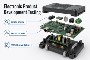
A microcontroller industrial design uses an MCU as the real-time control core of equipment that must operate around electrical noise, field wiring, temperature variation, vibration, long service cycles, and repeat production. The chip matters, but the complete controller also needs protected power, conditioned I/O, suitable communication, reliable firmware, a manufacturable PCB, and a test plan.
This guide explains how engineers can select an industrial MCU and turn it into a production-ready control board. It also draws a practical boundary between a custom MCU board and a PLC, so teams do not choose a low-cost chip and then underestimate the work needed to make the surrounding system reliable.
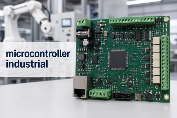
What Does “Microcontroller Industrial” Mean?
“Microcontroller industrial” describes the use of an MCU in industrial equipment, not a universal chip category with one fixed specification. A microcontroller combines a processor core, program memory, data memory, timers, communication peripherals, and configurable I/O in one integrated circuit.
In an industrial product, that MCU may read sensors, run control loops, generate PWM, manage alarms, communicate with a supervisory system, and place outputs into a safe state after a fault. The device must be selected for the actual electrical and environmental requirements, while the surrounding PCB supplies the protection and interfaces that the chip does not provide by itself.
For a broader explanation of the component and its assembly requirements, see our microcontroller unit PCB assembly guide.
What Makes a Microcontroller Industrial Grade?
A microcontroller industrial grade choice is one whose exact orderable part, package, temperature rating, lifecycle status, safety resources, and peripherals match the target equipment. The phrase “industrial grade” alone is not enough evidence.
Check the manufacturer datasheet and ordering information for:
- Operating temperature: verify the rated junction or ambient range for the exact suffix, not only the MCU family page.
- Supply supervision: brownout reset, power-on reset, watchdogs, clock monitoring, and error flags help the system respond to abnormal conditions.
- Memory integrity: error detection, ECC, CRC support, and documented retention or endurance may matter in long-life equipment.
- Peripheral fit: timers, PWM, ADCs, comparators, CAN, Ethernet, UART, SPI, and I2C must cover the real I/O plan without exhausting resources.
- Safety and security support: some MCU portfolios provide safety manuals, FMEDA data, diagnostic libraries, secure boot, or hardware security features for specific products.
- Availability: confirm product status, approved alternates, package supply, and the manufacturer’s longevity commitment before freezing the design.
The board still needs external transient protection, isolation, filtering, power conversion, and thermal design. A wide-temperature MCU on an unprotected PCB is not automatically an industrial controller.
Which MCU Architecture and Peripherals Fit the Application?
The best MCU is the least complex device that satisfies the timing, memory, peripheral, safety, software, and lifecycle requirements with practical margin. Core frequency alone is a poor selection method.
| Requirement | MCU Feature to Check | Typical Industrial Use |
| Simple sequencing and monitoring | GPIO, timers, ADC, watchdog | Sensor node, relay controller, small actuator |
| Motor or power control | High-resolution PWM, fast ADC, comparators, control accelerator | Drive, inverter, power converter, pump controller |
| Connected control | CAN, Ethernet MAC, multiple serial interfaces, security | Gateway, remote I/O, machine controller |
| Safety-related function | Safety documentation, diagnostics, memory protection, independent watchdog | Monitored shutdown, safety co-processor, protected actuator |
| High data or graphics load | More RAM, external-memory interface, DMA, display or camera support | HMI, vision-assisted controller, data acquisition |
Build a peripheral budget before choosing the package. Count ADC channels, timer channels, communication ports, DMA requests, interrupt sources, programming pins, oscillator pins, and spare I/O. Then check whether those functions can be used simultaneously on the selected pinout.
Microcontroller Industrial Applications
Microcontroller industrial applications are strongest where a product needs compact embedded control, repeatable timing, custom interfaces, and scalable unit cost. Common examples include:
- motor drives, pumps, fans, compressors, and positioning systems;
- sensor transmitters, condition-monitoring nodes, and data loggers;
- remote I/O modules, compact machine controllers, and protocol gateways;
- power supplies, inverters, battery-related controls, and energy meters;
- valve controllers, dosing equipment, thermal controllers, and laboratory instruments;
- human-machine interface panels and embedded diagnostic modules.
The MCU should be selected from the load and environment backward. A motor-control board may prioritize synchronized PWM and fast current sampling, while an industrial sensor node may prioritize low-noise analog acquisition, low power, secure communication, and stable calibration storage.
Microcontroller for Industrial Automation: When Is It a Better Fit Than a PLC?
A microcontroller for industrial automation is a better fit when the controller is embedded inside a repeatable product and the manufacturer can own the hardware, firmware, compliance, and lifecycle work. A PLC is usually better when users need modular field I/O, standardized programming, fast cabinet integration, and maintenance by plant technicians.
| Option | Best Fit | Main Trade-Off |
| Custom MCU board | High-volume or space-constrained product with fixed functions | Requires custom protection, firmware, validation, and lifecycle ownership |
| Industrial controller module | Embedded product needing prebuilt I/O or communication | Higher module cost and less hardware freedom |
| PLC | Machine or process automation maintained on the factory floor | Larger size and higher unit cost, but faster integration and service |
Some systems use both: an MCU controls a dedicated product or subsystem, while a PLC coordinates the machine. The right comparison is total engineering and lifecycle cost, not chip price versus PLC purchase price.
How Do Power, I/O Protection, and Isolation Prevent Failures?
Power conditioning, field-I/O protection, and isolation prevent predictable electrical stress from reaching the MCU. They must be designed around the real supply, cable length, load type, grounding system, and applicable immunity requirements.
- Power entry: define reverse-polarity, overcurrent, surge, transient, undervoltage, and inrush behavior before selecting regulators.
- Digital inputs: use current limiting, filtering, threshold control, and isolation where field voltage or ground offset requires it.
- Analog inputs: protect against overvoltage while controlling leakage, bandwidth, source impedance, and ADC settling error.
- Outputs: select drivers and clamps for the real relay, valve, solenoid, lamp, or motor load, including inductive energy.
- Communication ports: coordinate the transceiver, termination, common-mode range, ESD path, shield connection, and isolation strategy.
Protection parts work only when the PCB gives fault current a short, controlled path. Poor component placement or a long return trace can reduce the value of a correctly selected suppressor.
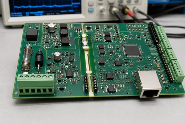
Which Industrial Communication Interfaces Matter?
The right industrial interface is the one required by the connected equipment, distance, timing, topology, and noise environment. The MCU peripheral is only one part of that interface.
- UART, SPI, and I2C: useful for short on-board links to sensors, memories, displays, and companion ICs.
- RS-485: practical for differential multidrop links, but the complete design must address termination, bias, grounding, and protocol timing.
- CAN: useful for robust multi-node control and diagnostics when the transceiver, termination, and message strategy are correctly designed.
- Ethernet: supports higher data rates and network integration, while adding magnetics, impedance, clock, connector, surge, and software requirements.
- Industrial Ethernet or fieldbus: may require dedicated controllers, licensed stacks, conformance testing, or a companion communication device.
Do not select an MCU because its feature list says “Ethernet” or “CAN” without checking the physical layer, software stack, certification path, and available CPU and memory after the application is running.
How Should an Industrial Microcontroller Board Be Designed?
An industrial microcontroller board should be partitioned by power level, noise source, signal sensitivity, isolation domain, and current-return path before detailed routing starts. Placement makes the protection and EMC strategy visible.
Useful board-level practices include:
- place decoupling capacitors at MCU supply pins with compact current loops;
- keep crystal and clock paths short and away from switching nodes;
- separate field connectors and protection components from low-voltage logic;
- route high-current and fast-switching loops before sensitive analog signals;
- maintain application-appropriate creepage, clearance, and isolation gaps;
- give Ethernet, USB, or other controlled-impedance routes a continuous reference plane;
- provide programming, reset, rail, communication, and critical-I/O test access;
- review connector retention, mounting holes, enclosure clearances, and service access.
Our custom PCB design for industrial use guide expands on enclosure, power, field wiring, and I/O planning.
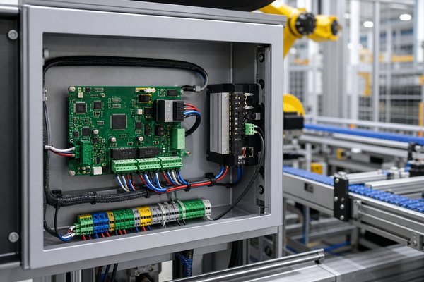
How Should Firmware, Watchdogs, and Functional Safety Be Planned?
Firmware reliability starts with defined fault responses, not with a watchdog added at the end. The hardware and software teams should agree on safe outputs, reset behavior, diagnostic coverage, update control, and recovery before board release.
- initialize outputs to a safe state before normal control begins;
- use brownout, clock, memory, and watchdog diagnostics where appropriate;
- verify that the watchdog is serviced by healthy task execution, not an unconditional loop;
- protect boot and update paths against incomplete or unauthorized firmware;
- record firmware version, configuration, and calibration data for traceability;
- separate independent shutdown hardware from normal software control when the risk analysis requires it.
IEC 61508 or another functional-safety standard applies at the system level, not merely because an MCU family offers safety documentation. Use the exact device safety manual and FMEDA package when the product’s hazard analysis calls for them, and verify the complete hardware, software, development, and validation process.
How Should PCB Assembly and Test Access Be Prepared?
Assembly and test should be designed before the first production panel because MCU boards combine fine-pitch packages, sensitive clocks, programming access, mixed-voltage I/O, and firmware-dependent tests. A complete build package reduces revision mistakes and fixture delays.
Prepare and control:
- Gerber or ODB++ data, drill files, stackup, fabrication drawing, and panel requirements;
- BOM with manufacturer part numbers, approved alternates, and do-not-substitute items;
- centroid data, assembly drawings, polarity information, and special handling notes;
- programming image, tool, connector, version rule, checksum, and serialization method;
- test-point map, fixture interface, input simulation, output loads, and pass/fail limits;
- inspection requirements for fine-pitch, QFN, BGA, through-hole, and hidden solder joints.
The production workflow should connect fabrication, sourcing, assembly, programming, and test. Our PCB manufacturing and assembly guide explains those handoffs, while the PCBA programming guide covers customer-provided firmware and production access.
What Should Engineers Validate Before Production?
Engineers should validate the board against its real operating envelope, fault cases, communication load, firmware image, and production test method before releasing volume builds. Bench function at room temperature is only the starting point.
- Confirm every rail during startup, normal load, communication activity, and output switching.
- Exercise minimum and maximum input conditions, sensor faults, disconnected cables, and defined overload cases.
- Check reset, brownout, watchdog, clock-failure, and firmware-update recovery behavior.
- Review thermal hot spots inside the intended enclosure and mounting orientation.
- Run the applicable EMC, ESD, surge, electrical-fast-transient, vibration, and environmental tests for the end product.
- Verify programming time, test coverage, traceability data, and fixture repeatability on pilot units.
- Freeze the approved BOM, firmware, manufacturing data, and test limits under one revision.
A second microcontroller industrial review should happen after pilot production: compare the designed test coverage with actual assembly findings, programming logs, and field-risk assumptions before scaling.
FAQ About Microcontroller for Industrial Automation
What microcontroller is used in industry?
Industry uses many MCU families from established semiconductor manufacturers. The correct device is chosen by real-time performance, memory, peripherals, temperature grade, safety and security resources, software ecosystem, package, availability, and cost rather than by one universal brand ranking.
What are industrial-grade microcontrollers?
Industrial-grade microcontrollers are exact MCU products rated and supported for specified industrial requirements, such as an extended operating-temperature range, long availability, robust diagnostics, or safety documentation. Verify the full part number and datasheet because ratings can differ within one family.
Is an STM32 microcontroller industrial grade?
Some STM32 devices and orderable variants target industrial applications, but “STM32” alone does not establish the temperature grade or safety support. Check the specific part number, package suffix, datasheet, product status, and required software or safety collateral.
Can ESP32 be used in industrial applications?
An ESP32-based design can be used in some industrial products if the exact device or module, temperature rating, RF requirements, lifecycle, security, power design, protection, enclosure, and compliance plan meet the application. A consumer development board should not be treated as a finished industrial controller.
Are microcontrollers used inside PLCs?
Many PLCs and industrial controllers use MCUs or processors internally, but the finished PLC adds protected I/O, power conditioning, communication, firmware, mechanical packaging, qualification, and a serviceable programming environment. The chip and the complete controller are not equivalent products.
What is the difference between a PLC and a microcontroller?
A microcontroller is an integrated circuit that must be designed into custom hardware, while a PLC is a finished industrial control platform with field I/O, power, enclosure, programming tools, and maintenance conventions. Custom MCU boards favor product integration; PLCs favor faster machine integration and field service.
Does an industrial MCU board need galvanic isolation?
Isolation is needed when the risk analysis identifies hazardous voltage, large ground-potential differences, noisy field wiring, or a required safety barrier. Not every interface needs isolation, and the barrier must include signal, power, creepage, clearance, and layout requirements.
Which communication protocol is best for an industrial MCU?
No protocol is best for every system. Choose according to distance, topology, data rate, determinism, interoperability, software stack, EMC environment, and conformance needs. RS-485, CAN, Ethernet, and application-specific industrial networks solve different problems.
What temperature range should an industrial microcontroller support?
The required range comes from the product’s measured internal temperature and specified operating environment. Select an exact MCU variant whose rated conditions cover that range with margin, then verify the board, components, enclosure, and thermal design under worst-case operation.
What files are needed to manufacture an industrial microcontroller board?
A complete package normally includes Gerber or ODB++ data, drill files, stackup and fabrication notes, BOM, centroid data, assembly drawings, programming files and instructions, test requirements, quantity, and approved revision information. Add enclosure, connector, coating, or traceability requirements when they affect production.
How Can EBest Circuit Support Your Industrial MCU Board?
At EBest Circuit, we support industrial control projects with PCB fabrication, component sourcing, SMT and through-hole assembly, inspection, customer-provided firmware programming, and test coordination. Our role is to connect the board data, BOM, assembly details, programming access, and acceptance criteria before production begins.
If your industrial MCU board is ready for review, send your Gerber or ODB++ files, BOM, centroid data, assembly drawing, firmware instructions, test requirements, quantity, and operating-environment notes to sales@bestpcbs.com. We will review the manufacturing and PCBA scope and identify the questions that should be resolved before quotation.