To decide whether group delay ripple comes from a PCB filter, first specify the passband, test boundaries and VNA aperture. Measure a known reference path and repeat the filter sweep under the same conditions. A flat insertion-loss trace alone does not prove that a modulated waveform passes through without distortion.
Group delay definition
Group delay describes how fast the transmission phase changes with frequency. In a band where transmission is strong enough and the phase slope is smooth over the signal bandwidth, it describes the delay of a narrowband signal envelope. The qualifier matters: a filter can delay different portions of a wide signal spectrum by different amounts, so a single number cannot describe what happens to the whole waveform.
Consider an illustrative receive-filter board for a radio near 1 GHz. The engineering question is whether the filter and its intended launches add more delay variation than the receiver allows across the occupied band. It is not whether a second PCB route matches the phase of the first route.
Group delay formula
Group delay is minus the derivative of unwrapped transmission phase with respect to angular frequency. In degrees and hertz, estimate it as −Δφ/(360 × Δf) seconds when Δφ is in degrees. This is a finite-interval estimate, not a guarantee that the slope remains constant between the two points.
For an instructional example, suppose unwrapped S21 phase changes from −82° at 995 MHz to −91° at 1,005 MHz. The difference is −9° over 10 MHz, giving +2.50 ns. If the instrument shows a phase jump at its display wrap boundary, do not use that displayed jump as the physical phase difference. See Keysight’s VNA group delay procedure.
Group delay vs phase delay
Use group delay to judge slope and waveform timing across frequency. Use phase delay only when the absolute phase and its reference convention are defined; a wrapped angle at one tone does not establish an unambiguous delay.
| Metric | Evidence and conditions | Use it when |
| Phase delay | Negative phase divided by angular frequency, with a defined phase branch and reference plane. | You need the equivalent delay of an individual sinusoid under that convention. |
| Group delay | Negative phase slope, with stated frequency interval, reference plane and usable transmission. | You need envelope transit time or in-band delay variation. |
| Insertion loss | Transmission magnitude at the same reference planes and terminations. | You need amplitude loss or want to flag low-signal regions where phase becomes unreliable. |
Group delay in filters
A filter can meet its amplitude mask and still delay parts of a waveform unequally. Inside the occupied band, variation in phase slope can smear a fast pulse or change the shape of a modulated symbol. Compare the delay curve with the system signal bandwidth instead of averaging over the entire instrument sweep.
For the receive board, check the occupied band with its allowed frequency offsets. A steep delay change outside that window may matter to a different operating mode, but it does not automatically fail the present mode. Conversely, do not arbitrarily trim an in-band peak simply to make the report pass.
Group delay ripple
Peak-to-peak group delay ripple is the maximum minus the minimum delay over the declared band, using the declared measurement setup. On the illustrative board, 2.80 ns maximum and 2.35 ns minimum give 0.45 ns peak to peak. If the project allows 0.40 ns maximum, that sweep exceeds the limit by 0.05 ns. It is not a confirmed defect until the measurement is suitable for separating that margin from setup variation.
| Test entry | Example only | Reason to retain it |
| Acceptance window | 990–1,010 MHz | Prevents a different sweep or stopband feature from changing the result. |
| Peak-to-peak limit | 0.40 ns | States the actual release metric; an average is not a substitute. |
| Aperture and point spacing | 2 MHz aperture; 0.25 MHz uniform points | Allows repeat sweeps with the same effective differentiation interval. |
| Decision conditions | Named reference planes, stable connections, reference sweep and repeat data | Helps judge whether a small apparent failure can be resolved. |
VNA group delay measurement
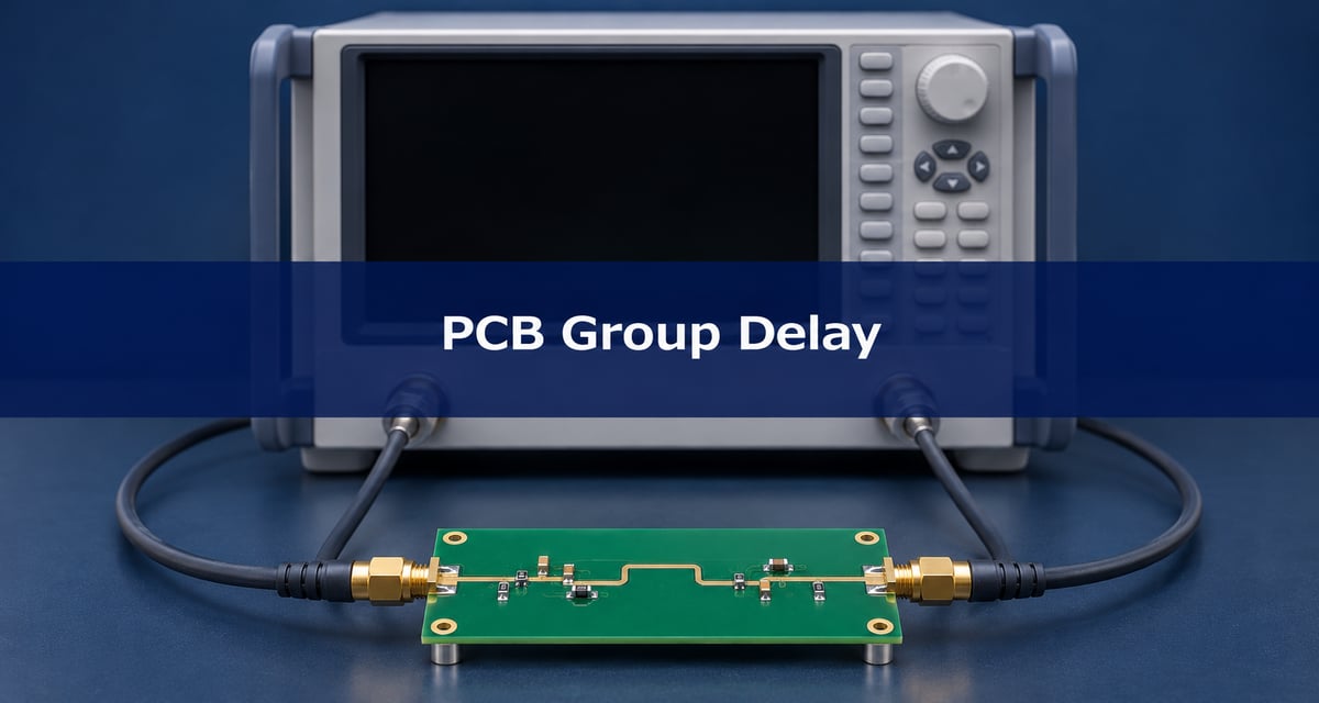
Use a calibrated two-port transmission measurement and define whether connectors and launches belong to the DUT. Start with a known thru or reference coupon rated for the test band. It need not show zero delay; the concern is whether it exhibits unexpected ripple or changes on reconnection.
Keep the cables stable, use the same port power and terminations, and retain complex S21 plus the setup file. If the specification excludes the fixture, use a validated correction for its actual geometry; a simple electrical-delay adjustment is not a substitute for removing mismatch and fixture effects. The PCB fixture de-embedding guide covers how to define that boundary.
Group delay aperture
Aperture is the frequency separation over which the analyzer estimates the phase slope. A larger aperture smooths the curve but can hide a narrow feature; a smaller one resolves finer detail but can make phase noise more obvious. Do not confuse aperture with the spacing between acquired points. The instrument may express aperture as points, hertz or a percentage of span.
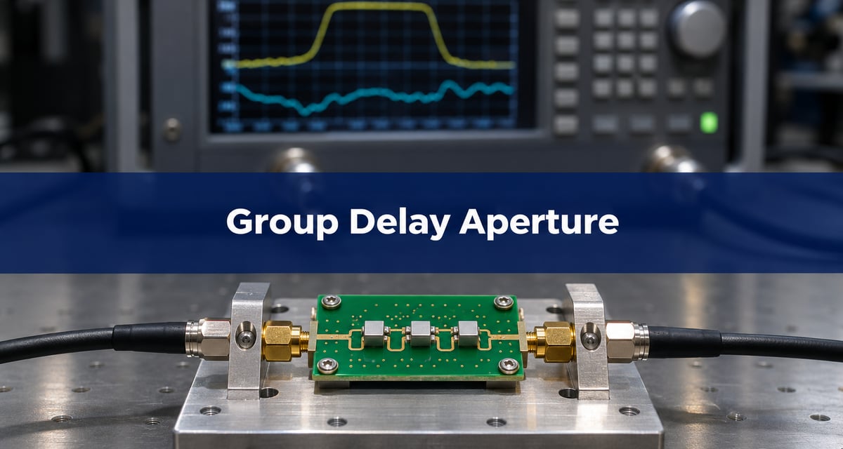
As a diagnostic check, repeat the sweep with two supported aperture settings while keeping the acquisition band and calibration fixed. A sharp spike that moves with settings or follows a noise floor calls for better measurement evidence. A repeatable feature may still shrink under heavier smoothing, so use the prescribed aperture for the acceptance result. Save both traces. Keysight’s aperture note also explains why edge points can disappear for wider intervals.
Group delay dispersion
Before attributing delay variation to the board, check whether the shape persists inside the usable passband, after reconnecting the DUT, and on another representative board if the decision warrants it. Compare the trace with insertion loss and return loss: a feature near a deep transmission null can have unstable phase and should not be used as evidence of passband behavior.
For the example, record the raw S-parameters, selected band, aperture, calibration or fixture file, curve extrema and location of the highest variation. If the reference is stable and the DUT exceeds the fixed limit in repeat tests with sufficient measurement margin, hold disposition for design review. If the reference shows similar variation, resolve the measurement problem before changing the PCB.
Frequently asked questions
Why does the trace drop out at the sweep ends?
The slope calculation may need points on both sides of the reported frequency. Sweep beyond the acceptance band so there are adequate points on either side, while retaining the actual window in the report.
Does flat group delay have to be zero?
No. A uniform delay can shift the arrival time without spreading the envelope. Check any separate latency requirement before deciding that a large constant offset is acceptable.
Can an S21 magnitude-only export be used?
No. It lacks the phase needed for the slope. Export complex S21, with frequency and port information, when the analysis will be repeated off the instrument.
Does more point density always cure phase wrapping?
It can help if large phase steps caused the ambiguity, but extra points do not improve a noisy transmission null. Verify both the spacing and the usable signal level.
Why does reconnecting an adapter change the result?
It can change the effective reference path or introduce a mismatch that was not accounted for by calibration. Record the adapter and verify a reference sweep after the connection change.
Can a negative value alone prove a faulty RF filter?
No. First check the reference convention, transmission level and phase processing. In a strongly dispersive region the phase slope can also yield an apparent negative delay without representing a signal traveling backward in time.
Does a TDR impedance check replace the group delay sweep?
No. TDR can locate impedance discontinuities, while a group delay sweep verifies transmission phase slope over the specified band. Use the two checks for different questions.
What goes in the production handoff?
Send the test boundaries, passband, limit, aperture, point spacing, fixture revision and report format. Link each result to its board revision and test state.
Discuss your RF PCB requirements
For a Best Technology fabrication review, send the stackup, RF launch or coupon geometry, and the intended measurement reference planes to sales@bestpcbs.com. Identify which connector and fixture structures the design includes.