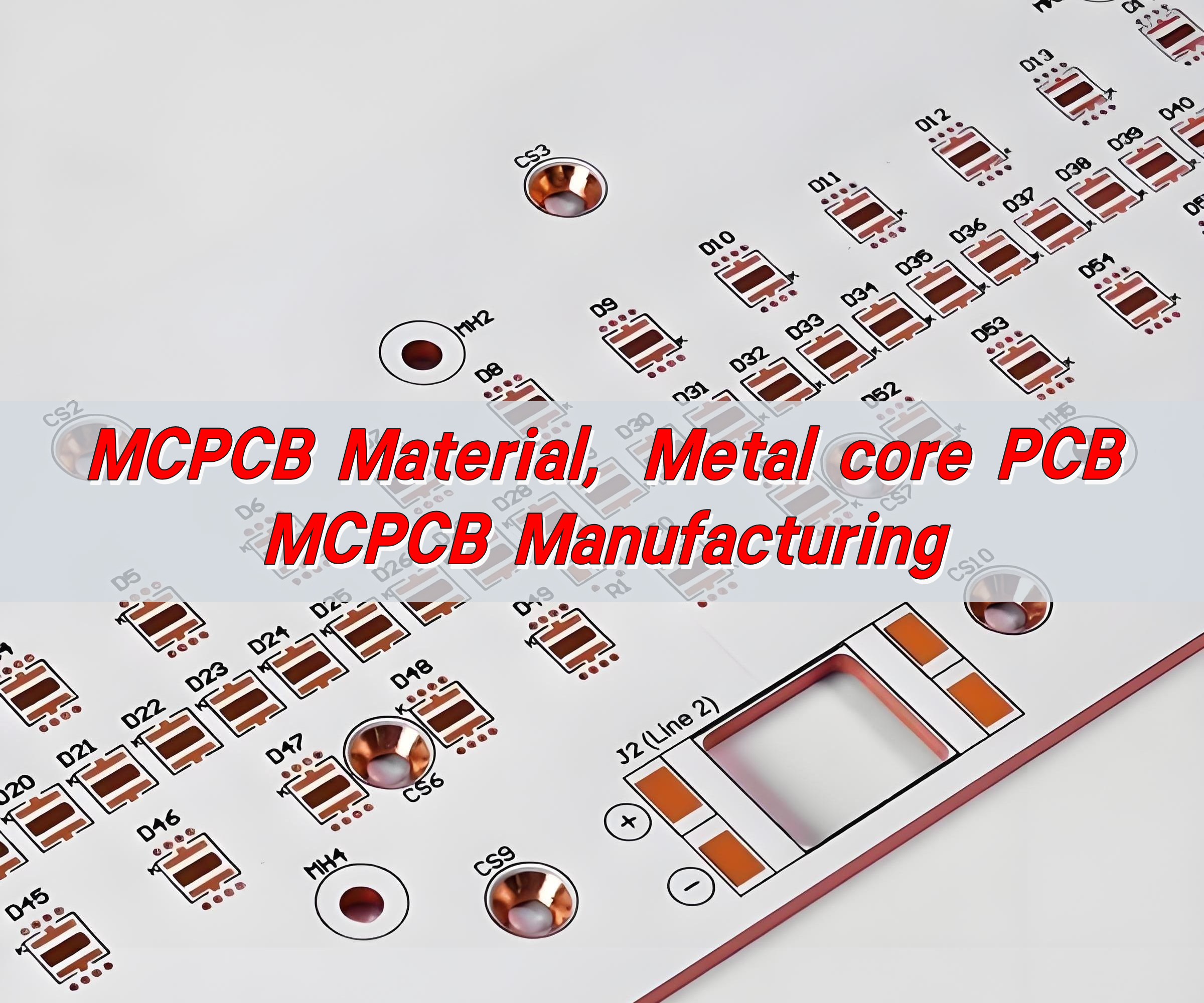
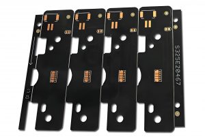
An EV charger MCPCB helps move heat away from switching devices, rectifiers, power resistors, and auxiliary power circuits as charging systems become smaller and more powerful. An MCPCB can move that heat into a chassis, heat sink, or cold plate more efficiently than a conventional board—but only when the board is designed as part of that thermal path.
EBest Circuit manufactures custom aluminum- and copper-base PCBs and provides component sourcing, assembly, and testing. We help charger developers match the board construction to the module instead of treating every PCB inside an EV charger as a metal-core board.
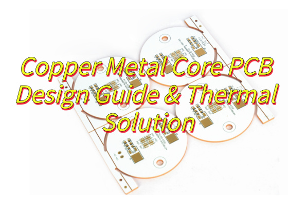
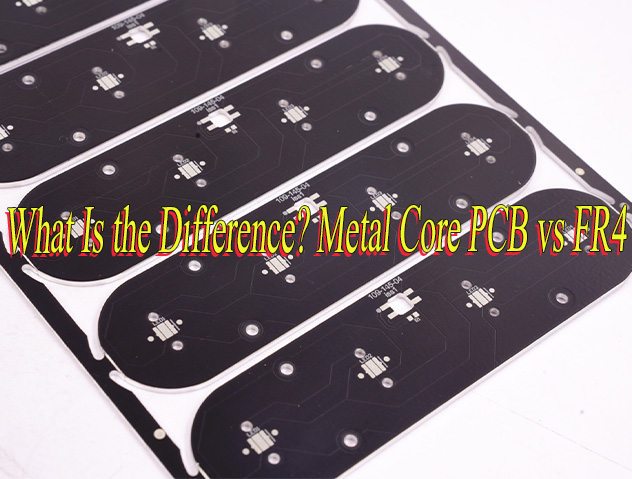
EV charger PCB is a broad term. EV charging PCB and electric vehicle charging PCB can refer to several different boards across the charging system. In this article, EV charger MCPCB means a metal-core board used within a defined power or thermal module—not every PCB in the system.
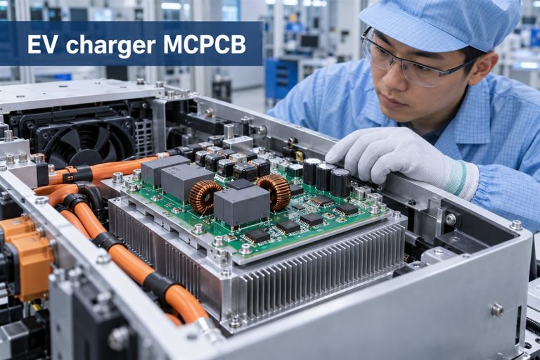
Where Does an MCPCB Fit Inside an EV Charger?
An MCPCB fits where heat is concentrated and there is a short, controlled path from the component to a metal cooling surface.
In an EV charger, that can include a compact power conversion board, a rectifier section, an auxiliary power module, or a board carrying high-loss switching devices. It can also be used for high-power status lighting. The metal base spreads heat beneath these components and transfers it toward the charger housing, a heat sink, or a cold plate.
It is usually not the first choice for communication, metering, display, or central control boards. Those boards often need multilayer signal routing, controlled impedance, dense interconnections, or isolation between several electrical domains. FR-4, heavy-copper PCB, insulated metal substrate, ceramic, and hybrid structures each solve different problems.
Application labels also need clear boundaries. An EVSE PCB belongs to stationary charging equipment, while an on-board charger PCB, or OBC PCB, operates inside the vehicle. A DC fast charging PCB may describe a control board, gate-driver board, or power-module board with very different construction needs. An EV charger control board is usually not an MCPCB unless it also carries concentrated heat into a defined cooling surface. Supplier listings may use the phrase EV charging board PCB, but that wording is too broad to specify the correct board technology.
The practical dividing line is simple:
- Use an MCPCB when the PCB must conduct heat into a defined cooling surface.
- Consider another construction when routing density, high-voltage spacing, or complex multilayer connections dominate the design.
That distinction keeps the thermal board focused on the part of the charger where it creates measurable value.
When Does EV Charger PCB Design Require a Metal Core?
Choose a metal core PCB for EV charging when temperature cannot be controlled reliably through copper area, thermal vias, airflow, and a conventional laminate alone.
This often happens when several conditions appear together: high component loss, limited board area, restricted airflow, and direct mechanical contact with a heat sink or enclosure. In that situation, the metal base becomes a heat-spreading layer rather than simply a stronger board material.
For example, a power semiconductor may operate safely on FR-4 at a moderate load but exceed its temperature target when the same circuit is packaged into a smaller charger. Moving to an MCPCB can shorten the heat path. The result depends on the entire structure—from the component pad and copper circuit through the dielectric layer and metal base to the external cooling surface.
A metal core is less useful when the main limitation is elsewhere. It will not correct an undersized heat sink, poor board-to-housing contact, excessive semiconductor loss, or insufficient airflow. It may also complicate a design that needs many signal layers or long high-voltage creepage paths.
The choice should therefore be based on the module’s losses, allowable temperatures, mechanical interface, and insulation requirement—not on charger power alone.
Which PCB Material Fits Your EV Charger Application?
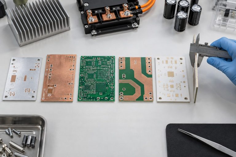
The right material depends on the job of the board. An EV charger normally uses more than one PCB technology because heat transfer, current carrying, signal routing, isolation, and mechanical requirements do not peak in the same place.
- Aluminum MCPCB fits cost-sensitive thermal modules that need to spread component heat into a housing or heat sink. It is a practical choice when the layout is relatively simple and aluminum can keep the hot spots within the temperature target.
- Copper-base MCPCB fits smaller or more demanding thermal modules where heat is highly concentrated and stronger lateral heat spreading is needed. It can improve the path away from a power device, but it also increases material cost and board weight.
- High-Tg FR-4 fits control, communication, sensing, and multilayer power-control boards that need routing density, plated through-holes, and high-voltage separation. Its higher glass-transition temperature improves dimensional and thermal stability, but High-Tg does not mean high thermal conductivity.
- Heavy-copper PCB fits high-current distribution, terminals, relays, and power paths where conductor temperature rise is the main concern. It carries more current and adds thermal mass, but it does not provide the same direct board-to-heat-sink path as an MCPCB.
- Ceramic PCB fits compact modules that need strong electrical insulation, high-temperature stability, low expansion, or high thermal performance. It can be valuable around demanding power devices, but cost, size, brittleness, copper attachment, and assembly handling must be considered.
Many chargers need a mixed solution rather than one material throughout the product. For example, a High-Tg FR-4 control board can manage communication and safety functions, a heavy-copper board can distribute current, and an aluminum, copper-base, or ceramic board can support the most concentrated thermal load.
Use the dominant engineering problem as the first filter:
- heat must move into a chassis or heat sink → aluminum or copper-base MCPCB;
- high current must travel across the board → heavy-copper PCB;
- multilayer signals and isolation dominate → High-Tg FR-4;
- high temperature, insulation, and dimensional stability dominate → ceramic PCB.
Final selection still depends on operating voltage, loss distribution, cooling design, board size, production quantity, and target cost. A material comparison is useful only when it is tied to the actual EV charger module.
What Thermal Management Risks Should Be Checked in an EV Charger MCPCB?
The main risk is assuming that a high thermal-conductivity material automatically produces a cool, reliable assembly. Heat must cross several interfaces, and the weakest one can control the result.
- A thick dielectric layer can restrict heat flow. It may provide stronger isolation, but it also increases thermal resistance. The correct balance depends on operating voltage and heat density.
- A high average board temperature can hide local hot spots. Temperature should be checked beneath the switching device and at its thermal pad, not only at the edge of the board.
- Poor contact can cancel the benefit of the metal base. Board flatness, interface material, screw position, mounting pressure, and heat-sink finish affect real performance.
- Copper geometry affects both current and temperature. Narrow current paths, connector transitions, or insufficient copper around a power device can create additional heat before it reaches the base metal.
- Thermal cycling creates mechanical stress. Different expansion rates among components, solder joints, copper, dielectric, and metal base can reduce long-term reliability.
- Electrical isolation cannot be traded away for lower thermal resistance. Dielectric withstand, creepage, and clearance remain essential in charger hardware.
A useful thermal review follows the heat from its source to the final cooling surface. It does not stop at the MCPCB datasheet value.
What Should Buyers Specify for DC Fast Charging Boards?
For DC fast charging, buyers should first specify the function of the board. A control PCB, gate-driver board, power module, and communication board experience different voltage, current, heat, and isolation conditions.
For the MCPCB itself, the most influential requirements are:
- operating and peak current;
- voltage and dielectric withstand requirement;
- expected component losses and hot-spot locations;
- aluminum or copper base;
- dielectric thickness and thermal performance;
- copper weight and critical current paths;
- finished thickness, flatness, and mounting tolerances;
- connection to the heat sink, housing, or cold plate;
- operating environment and temperature range.
These details matter more than requesting the “highest thermal conductivity.” A thinner dielectric may improve heat transfer but must still meet isolation needs. A copper base may spread heat effectively but can add unnecessary cost and weight if an aluminum base already meets the temperature target.
Buyers should also define whether the order covers bare boards or completed assemblies. If components, thermal interface materials, busbars, connectors, or heat sinks are part of the build, they should be considered together because they change the assembly process and final thermal path.
How Should EV Charger PCB Assembly Be Qualified?
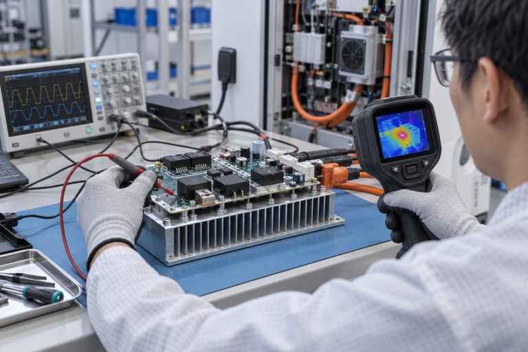
An EV charger PCBA should be qualified by proving that the assembled module performs as intended under representative electrical, thermal, and mechanical conditions. This is the practical purpose of EV charger PCB assembly qualification.
Start with the failures that matter to the product. A power board may need confirmation of current handling, isolation, temperature rise, and solder integrity. A module attached to a housing may also need verification of flatness, contact pressure, connector alignment, and repeated thermal cycling.
Inspection methods should match the assembly:
- AOI can verify polarity, placement, and visible solder joints.
- X-ray can examine solder beneath power packages and thermal pads.
- Electrical tests can check continuity, isolation, and withstand performance.
- Functional testing can confirm that the module operates at its intended load.
- Temperature measurements can reveal whether heat reaches the cooling surface without an excessive local hot spot.
The prototype should be tested in a realistic mechanical setup. Testing a loose board on a bench cannot represent a design that relies on a chassis or cold plate. Once the module passes, the approved material, stack-up, component revision, mounting method, and test limits should remain consistent for repeat production.
How Do You Choose an EV Charger Circuit Board Manufacturer?
Choose an EV charger PCB manufacturer that understands both sides of the project: how to build the metal-core board and how that board functions inside the charger.
A capable supplier should be able to explain why the proposed base metal, dielectric, copper weight, surface finish, and assembly process fit the module. If a different PCB construction would serve the application better, the supplier should identify that before production rather than simply quoting the requested material.
Coordination also affects the result. When bare-board fabrication, component sourcing, assembly, and testing are handled separately, a thermal or soldering issue can fall between suppliers. A coordinated PCB and PCBA workflow makes it easier to connect material decisions with component packages, solder profiles, mechanical interfaces, and acceptance tests.
EBest Circuit supports prototypes, small batches, and repeat production through PCB manufacturing, component sourcing, PCBA, and testing. One business contact works with an engineering support team to coordinate technical questions. DFM review can identify conflicts involving the board structure, component spacing, panelization, assembly access, and testability before the build begins.
For programs that require formal quality controls, available certifications include ISO 9001, ISO 13485, IATF 16949, and AS9100D. The applicable production site, documentation, inspection level, and customer requirements should be confirmed for the individual project.
The strongest manufacturing partner is the one that reduces uncertainty before the prototype and preserves the approved solution when the project moves into repeat production.
Why Choose EBest Circuit as Your EV Charger Circuit Board Manufacturer?
EBest Circuit gives EV charger developers one coordinated route from a thermal-board concept to an assembled and tested product. Instead of separating the bare board, components, assembly, and engineering questions among several suppliers, customers work with one business contact supported by three engineers throughout the project.
This is especially useful for an EV charger MCPCB because the board material cannot be separated from the power package, solder joint, mounting surface, and cooling structure. Our engineering support connects these decisions before production:
- DFM review covers the MCPCB structure, dielectric, copper, tolerances, panelization, component spacing, and test access.
- PCB fabrication, component sourcing, PCBA, and testing can be managed as one project.
- Prototype and small-batch support helps engineers check electrical operation, mechanical fit, and thermal behavior before repeat production.
- A supply network of more than 1,000 partners supports component and material sourcing while our own PCB and PCBA factories coordinate production quality and timing.
- Digital production records allow material and product batches, manufacturing progress, and production history to be traced quickly.
EBest Circuit has 20 years of PCBA experience and has served more than 10,000 engineers and 1,800 customers. Available quality-system certifications include ISO 9001, ISO 13485, IATF 16949, and AS9100D. The applicable factory, inspection plan, documentation, and certification requirements are confirmed according to the individual EV charging project.
For customers, the practical benefit is a shorter path from an engineering question to a build decision—and fewer gaps between MCPCB fabrication, assembly, thermal integration, and testing.
FAQs About EV Charger MCPCB
Does every EV charger need an MCPCB?
No. An EV charger may contain several board types. MCPCB is most suitable for a board that must transfer concentrated component heat into a metal cooling structure.
Is aluminum or copper better for an EV charger MCPCB?
Aluminum is often sufficient for cost-effective heat spreading. Copper can spread heat more aggressively but adds cost and weight. The right choice depends on losses, board size, cooling design, and temperature targets.
Does higher thermal conductivity always produce a cooler board?
No. Dielectric thickness, copper layout, component attachment, interface material, mounting pressure, and the external heat sink can have as much influence as the published conductivity value.
Can one supplier manufacture and assemble the board?
Yes. Combining fabrication, component sourcing, PCBA, and testing can reduce handoff risks, especially when power packages, thermal pads, heavy connectors, or a defined cooling interface are involved.
What should a prototype prove?
It should prove electrical operation, isolation, temperature behavior, solder quality, mechanical fit, and contact with the intended cooling surface under representative conditions.
Can an approved prototype move directly into repeat production?
It can move forward after the material, stack-up, components, assembly method, mechanical interface, and acceptance limits are frozen. Any later substitution should be reviewed for electrical, thermal, and mechanical impact.
Need a custom EV charger MCPCB for a power or thermal module? Send your Gerber files, BOM, board drawing, operating conditions, quantities, and testing needs to sales@bestpcbs.com. EBest Circuit can review the construction and provide a coordinated fabrication and assembly quotation.