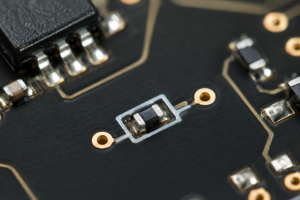
Embedded resistors in PCB manufacturing are resistive elements formed inside the board rather than installed as separate surface-mounted components. They free up component space, reduce resistor placements, and can shorten electrical connections. For compact products, this moves selected circuit functions into the bare board while leaving more surface area available for other components.
The manufacturing challenge is to deliver the required resistance consistently, not simply to produce a conductive pattern. Material variation, etching accuracy, temperature, and electrical loading all affect the result. Understanding how those factors translate into measurable resistance changes helps engineers and purchasing teams evaluate the finished product.
What Are Embedded Resistors in a PCB?
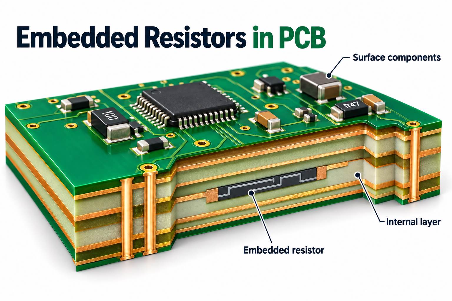
Embedded resistors are passive elements integrated into a PCB’s internal circuit layers. They perform functions such as termination, biasing, and voltage division, with the resistive structure forming part of the laminated board.
In a common thin-film construction, a resistive alloy is deposited on copper foil and bonded to a dielectric. Selective etching exposes the resistor body while retaining copper terminals at its ends. Current flows through the film between those terminals, and subsequent lamination encloses the structure inside the PCB.
This process differs from placing a packaged chip resistor inside a cavity. The thin-film element receives its final resistance through material properties and patterned dimensions, making its value a characteristic of the manufactured board. This article focuses on that foil-based construction.
How Do Embedded Resistors Compare with Surface-Mount Resistors?
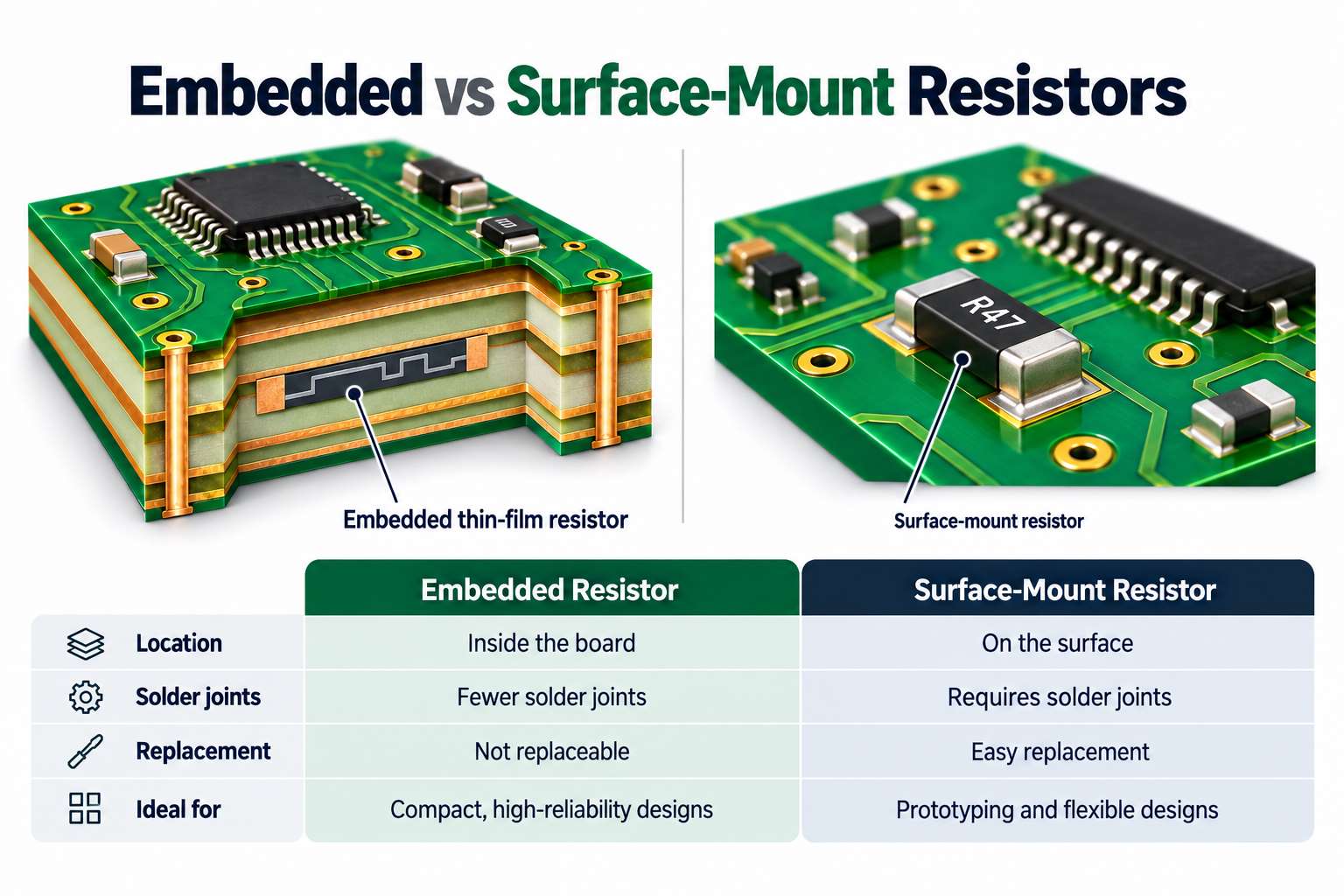
Embedded resistors reduce surface occupancy and individual component connections. Surface-mount resistors provide easier access for value changes, replacement, and calibration. The practical choice depends on which functions benefit from integration and which need to remain adjustable.
| Comparison | Embedded Thin-Film Resistors | Surface-Mount Resistors |
|---|---|---|
| Location | Internal circuit layers | Board surface |
| Connection | Resistive film connected directly to copper terminals | Component terminations connected through solder joints |
| Production stage | Formed during PCB fabrication | Placed and soldered during assembly |
| Resistance control | Material and processing establish the finished value | Purchased component specification, with assembly effects considered |
| Value changes | Usually require revised fabrication data | Often possible through component substitution |
| Replacement | Limited access after lamination | Accessible for component-level replacement |
The electrical benefit comes from the resulting interconnect, rather than burial alone. Shortening a connection can reduce parasitic inductance and capacitance. In RF circuits, the relevant result is the performance of the complete connection across the operating band.
Removing a chip resistor also removes its component-to-board solder joints, but adds resistor formation and verification to PCB fabrication. A mixed construction can embed stable termination functions while keeping tuning and calibration resistors on the surface.
What Materials Are Used for Embedded PCB Resistors?
Foil-based embedded resistors commonly use nickel-phosphorus or nickel-chromium resistive alloys combined with copper and a compatible dielectric. The alloy provides the resistance; the copper supplies the terminals and conductors, while the dielectric supports and insulates the structure.
| Resistive Material | Typical Construction | Manufacturing Consideration |
|---|---|---|
| Nickel-phosphorus, or NiP | Electrodeposited resistive alloy on copper | Selective processing must preserve the resistor film and copper terminals |
| Nickel-chromium, or NiCr | Vacuum-deposited resistive alloy on copper | Etching chemistry and sequence must match the alloy and foil construction |
Material grades are described by sheet resistance, expressed in ohms per square, or Ω/□. This is different from the finished resistor value. For example, a uniform 50 Ω/□ film patterned into a simple rectangle with an effective length-to-width ratio of 2:1 gives a nominal 100 Ω before manufacturing variation.
The dielectric is a separate part of the specification. Suitable constructions can use FR4, high-frequency laminates, or polyimide, provided the complete material combination is compatible with processing and service conditions. A flexible circuit also requires verification under its intended bending conditions.
Copper thickness, surface treatment, adhesion, and lamination behavior influence manufacturing consistency. A replacement material therefore needs more than a matching sheet-resistance value: its complete construction must remain compatible with the approved production process.
How Are Embedded Resistors Manufactured in a PCB?
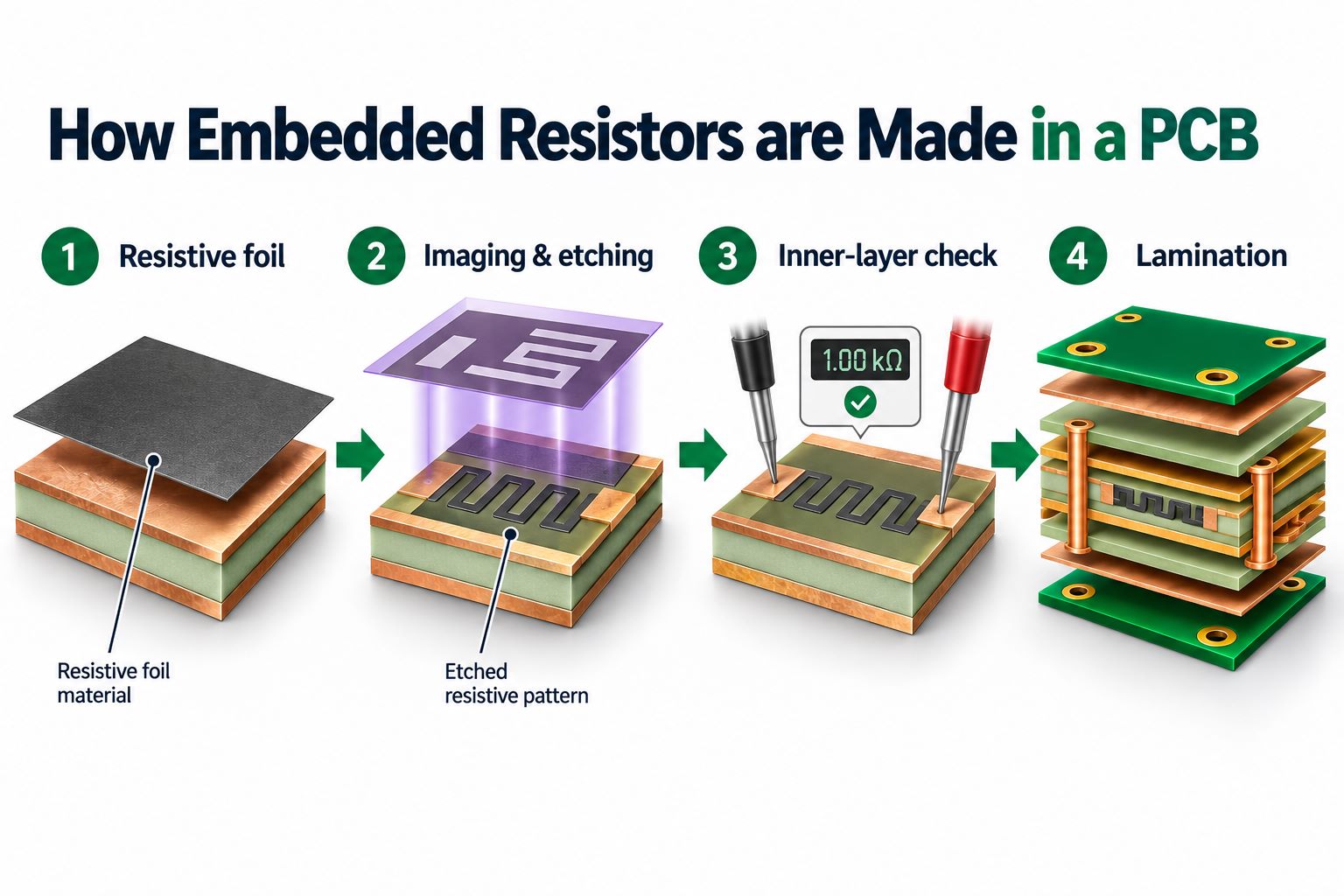
Embedded thin-film resistors are produced through imaging, selective etching, inspection, and lamination. In a typical nickel-phosphorus process, two imaging operations define the combined circuit and then the exposed resistor bodies.
- Prepare the resistor laminate. Check material identification, surface condition, and handling. The copper, resistive film, and dielectric must be suitable for the intended chemical and thermal processing.
- Form the combined circuit pattern. Photoresist protects the required conductor and resistor areas. Unwanted copper is removed, followed by unwanted resistive material outside the circuit pattern.
- Expose the resistor bodies. A second image protects the copper conductors and terminals. Selective copper removal exposes the film that will carry current through each resistor.
- Inspect and measure the inner layer. Optical inspection checks geometry and visible defects. Electrical measurements establish resistance while the patterned elements remain accessible.
- Laminate and complete the board. The resistor layer is incorporated into the multilayer structure. Subsequent fabrication and final electrical testing complete the production sequence.
The etching route depends on the alloy. Some nickel-chromium processes remove unwanted copper and resistive material together during the initial circuit etch, reducing the need for a separate resistor-film removal stage.
Registration and etching at the copper-to-resistor boundary determine the effective element dimensions. Measurements before and after later processing help distinguish variation introduced during resistor formation from changes associated with lamination or subsequent operations.
Production records should connect material lot, artwork revision, and resistance measurements. This makes a resistance shift traceable to the relevant stage rather than leaving the investigation dependent on the final test result alone.
What Resistance Values and Tolerances Can Embedded Resistors Achieve?
Foil-based constructions can produce values from a few ohms through tens of kilohms, depending on material and geometry. Finished tolerance must be established for the actual process. A 100 Ω ±10% requirement, for example, means acceptance between 90 and 110 Ω at the specified measurement stage and conditions.
Three requirements need to remain separate:
| Requirement | What It Specifies |
|---|---|
| Material tolerance | Variation in the supplied film’s sheet resistance |
| Finished resistance tolerance | Deviation from the target value after a defined manufacturing stage |
| Stability limit | Permitted change after specified thermal, environmental, or electrical loading |
Consider a 100 Ω target with an assumed ±5% sheet-resistance variation and ±3% variation in the effective length-to-width ratio. Combining the worst-case limits gives 100 × 0.95 × 0.97 = 92.15 Ω at the lower end and 100 × 1.05 × 1.03 = 108.15 Ω at the upper end.
The calculated upper value is only 1.85 Ω below a 110 Ω acceptance limit, before any additional processing shift. A ±5% material specification does not automatically produce a ±5% finished resistor. This example shows how material and dimensional variation consume the available tolerance allowance.
Actual production results also depend on film uniformity, imaging accuracy, etching consistency, and later processing. Smaller features are more sensitive to a given absolute dimensional error, so the same material can produce different tolerance outcomes in different geometries.
Tighter requirements may involve trimming while the resistor remains accessible. The adjusted element must still meet the final acceptance limits after the remaining manufacturing steps; an accurate pre-lamination reading alone does not establish finished-board accuracy.
How Do Power and Temperature Affect Embedded Resistor Performance?
Power generates heat, while temperature changes the operating resistance and can affect long-term stability. The useful operating limit is therefore the load at which the resistor remains within its electrical requirements, not simply the point before it fails open.
Temperature-related resistance change
The temperature coefficient of resistance, or TCR, estimates how much resistance changes with temperature. Assuming a constant coefficient over the interval:
Resistance change (%) = TCR (ppm/°C) × temperature change (°C) ÷ 10,000.
Consider two resistors that each measure 100 Ω at 25°C, with assumed positive temperature coefficients of 50 and 100 ppm/°C. If both resistor bodies reach 85°C, the estimated changes are:
| Assumed Temperature Coefficient | Temperature Rise | Estimated Resistance Change | Estimated Operating Resistance |
|---|---|---|---|
| +50 ppm/°C | 60°C | +0.30% | 100.30 Ω |
| +100 ppm/°C | 60°C | +0.60% | 100.60 Ω |
If the circuit allows temperature effects to contribute no more than 0.5%, the second example exceeds that allowance. The first remains within this particular budget, but initial manufacturing error and permanent drift still need separate consideration.
The relevant temperature is the resistor body’s temperature, including self-heating. An enclosure at 85°C does not establish an 85°C resistor temperature. Nearby copper, dielectric thickness, and heat paths determine how far the element rises above its surroundings.
Power loading and stability
At a nominal 100 Ω, increasing current from 10 mA to 20 mA raises heat generation from 10 mW to 40 mW. Doubling current quadruples power when resistance is held constant. The calculation establishes the electrical load; the actual temperature rise depends on the PCB’s thermal behavior.
Power qualification should assess both behavior under load and resistance after cooling to the reference temperature. A resistor can remain conductive while drifting outside its stability limit. Continuous-use capability therefore requires more than a brief overload-survival result.
Pulse loading
An illustrative 1 W rectangular pulse lasting 1 ms every 10 ms produces 0.1 W average power and 1 mJ per pulse. Average power alone does not establish safe operation: peak temperature also depends on pulse duration and the element’s thermal response. Pulse assessment includes amplitude, duration, and repetition rate.
How Are Embedded Resistors Tested During PCB Manufacturing?
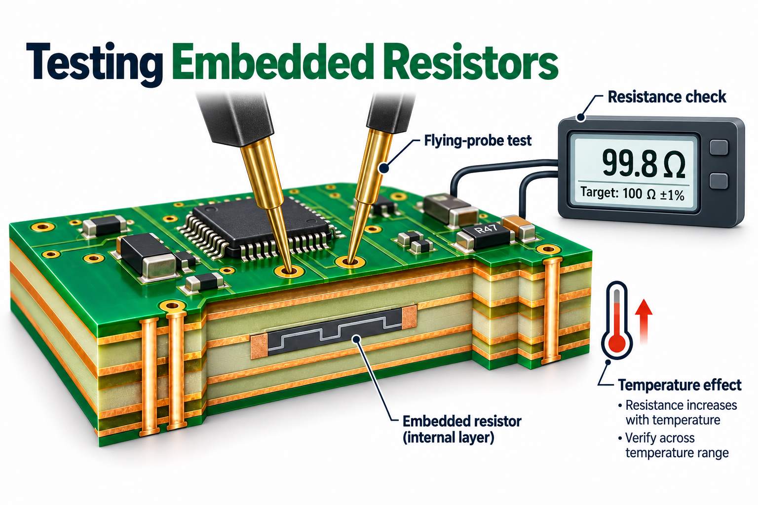
Embedded resistors are verified by resistance measurements, supported by pattern inspection and normal PCB continuity and isolation checks. The test program must identify whether a reading represents one resistor or an interconnected network.
Before lamination
Optical inspection checks for copper remnants, damaged film, dimensional errors, and irregular terminal geometry. Measurements through the copper terminals verify the electrical result. Process-control coupons track manufacturing variation, while product measurements provide the coverage specified for the actual circuit.
Finished-board measurement
A resistor-capable flying-probe or fixture-based system accesses the completed board’s test nodes. Two ideal 100 Ω resistors in parallel measure 50 Ω, but 90 Ω and 112.5 Ω also produce 50 Ω. A correct network reading therefore cannot, by itself, prove that both elements meet a 100 Ω ±10% requirement.
Measurement connections matter as well. An assumed 0.2 Ω of combined lead and contact resistance adds 2% to a 10 Ω two-wire reading. Four-wire sensing separates current delivery from voltage measurement, reducing that contribution. Controlled test current limits self-heating, and a defined temperature keeps measurements comparable.
Stability and acceptance
Consider an illustrative 100 Ω resistor measuring 100.4 Ω before a specified stress exposure and 101.0 Ω afterward, both at the same reference temperature. Its final nominal error and its change from the measured baseline give different acceptance results:
| Check | Calculated Result | Example Requirement | Decision |
|---|---|---|---|
| Final error from 100 Ω nominal | +1.0% | Within ±10% | Pass |
| Change from the 100.4 Ω baseline | Approximately +0.60% | No more than 0.5% | Fail |
A broad nominal tolerance can therefore hide an unacceptable stability change unless both quantities are reported. Test records should identify the element or network, measured values, reference conditions, acceptance limits, and board or lot, with qualification sampling distinguished from routine production coverage.
Where Are Embedded Resistors Used?
Embedded resistors suit stable circuit functions that benefit from close integration with the PCB. The most relevant applications combine a clear electrical purpose with a practical need for compact interconnections or reduced surface occupancy.
- High-speed communication and computing boards: Series or parallel termination can be integrated near the relevant circuit layer, freeing surface space around dense component areas.
- RF and microwave assemblies: Power dividers, combiners, attenuators, and equalizers can incorporate thin-film elements. In a Wilkinson divider, the isolation resistor becomes part of the printed RF network.
- High-density modules and package substrates: Pull-up, pull-down, bias, and voltage-divider functions can be embedded where their accuracy and stability requirements match the manufacturing process.
- Localized heating: Patterned resistive foil can form a heater inside the board. Here, qualification focuses on temperature distribution, operating load, and thermal cycling.
The application determines the evidence needed. DC resistance supports resistor acceptance, while an RF network also needs performance verification across its operating band. A heater is evaluated against its thermal requirements rather than a signal-termination specification.
When Are Embedded Resistors Cost-Effective?
Embedded resistors are cost-effective when savings in components, assembly, or packaging justify the added PCB material, processing, and testing. The useful comparison is cost per accepted assembled board, including yield and rework, rather than bare-board price alone.
Replacing 200 two-terminal chip resistors removes 200 component placements and 400 component-to-board solder joints. The remaining assembly may still need the same reflow pass, so reduced placement work should not be counted as eliminating an entire soldering operation.
| Cost Group | Items to Include |
|---|---|
| Added fabrication cost | Resistive material, imaging and etching, resistance testing, qualification, and yield effects |
| Removed assembly cost | Purchased resistors, their placement, and related solder-joint inspection |
| Product-level value | Usable board area, enclosure fit, and required electrical performance |
A hypothetical break-even calculation makes the comparison clearer. Assume one-time qualification costs of $1,200 and a recurring saving of $1.20 per accepted assembly after all affected production costs. Break-even occurs at 1,000 boards; producing 2,000 boards gives a net saving of $1,200.
These inputs illustrate the calculation rather than market pricing. Higher resistor density can distribute material and imaging costs across more functions, while frequently changed resistor values may favor surface-mounted parts during development. Both cases should be evaluated against the expected production volume.
What Should You Confirm Before Ordering an Embedded Resistor PCB?
An embedded-resistor PCB order needs identifiable resistor elements, a complete material construction, and measurable acceptance criteria. Fabrication and assembly documents must distinguish formed resistors from discrete parts that still require purchasing and placement.
| Order Information | Details to Include |
|---|---|
| Resistor schedule | Reference identifiers, target values, finished tolerances, and electrical connections |
| Material construction | Resistive grade, sheet resistance, copper thickness, dielectric, and layer location |
| Fabrication files | Gerber or ODB++ data, resistor artwork, netlist, stackup, and controlled drawing revision |
| Operating conditions | Continuous load, pulse profile, temperature range, and stability requirements |
| Testing | Accessible nodes, individual or network measurements, coverage, reference conditions, and acceptance limits |
| Production scope | Prototype and repeat quantities, assembly scope, material availability, and delivery requirements |
The resistor schedule should map directly to the artwork and test program. A requirement such as 100 Ω ±10% also needs an acceptance stage and measurement conditions. Any post-exposure drift limit belongs in a separate field rather than being folded into the nominal tolerance.
Material substitutions require review of processing and thermal behavior as well as sheet resistance. Once the sample build is approved, the released construction, fabrication data, and test limits become the reference for repeat production.
For mixed assemblies, the schematic can show both embedded and discrete resistors. The assembly BOM and placement data should identify which positions require physical components, preventing embedded functions from being purchased or placed a second time.
FAQs About Embedded Resistors in PCB
1. Do embedded resistors require an extra PCB layer?
Not necessarily. Thin-film resistors can share an existing circuit layer with copper conductors. Whether another layer is needed depends on the available area, electrical connections, and complete board construction.
2. Can embedded resistors be used in flexible PCBs?
Yes. Suitable polyimide-based resistive laminates support flexible and rigid-flex constructions. The finished circuit still needs verification for its intended bend radius and number of flex cycles; material compatibility alone does not establish dynamic-flex life.
3. Can one resistive layer contain different resistor values?
Yes. Different patterned dimensions produce different nominal values from the same sheet-resistance material. Each resistor retains its own target value, finished tolerance, and acceptance requirement in the production data.
4. Can embedded resistors be replaced after lamination?
A buried thin-film resistor is generally not replaceable like a surface-mounted component. Any repair or alternative connection requires board-level assessment and an approved method that preserves the intended circuit function.
5. Can embedded resistors and capacitors be used in the same PCB?
Yes. Compatible embedded-passive constructions can incorporate both functions. Their resistance, capacitance, dielectric, and manufacturing requirements need to be evaluated together within the proposed board structure.
EBest Circuit provides PCB fabrication, component sourcing, and PCB assembly services. For embedded resistors in PCB manufacturing, send your fabrication files, resistor schedule, material requirements, and quantities to sales@bestpcbs.com for an engineering review.
Include the finished resistance limits, operating load, and required test coverage. These requirements give our team a clear basis for evaluating manufacturability, verification, and quotation scope before production.