An electronic speed controller working correctly converts a throttle command into controlled current through a motor. It decodes the command, determines the required switching state, drives power MOSFETs with pulse-width modulation (PWM), monitors electrical and thermal conditions, and disables or limits the output when a verified protection threshold is crossed.
The operating principle changes with the motor. A brushed ESC varies current through one winding path, while a brushless ESC electronically commutates multiple phases according to measured or estimated rotor position. Reliable operation therefore depends on the complete system: command protocol, firmware, gate drivers, power stage, sensing, PCB layout, motor, power supply, wiring, cooling, and protection settings.
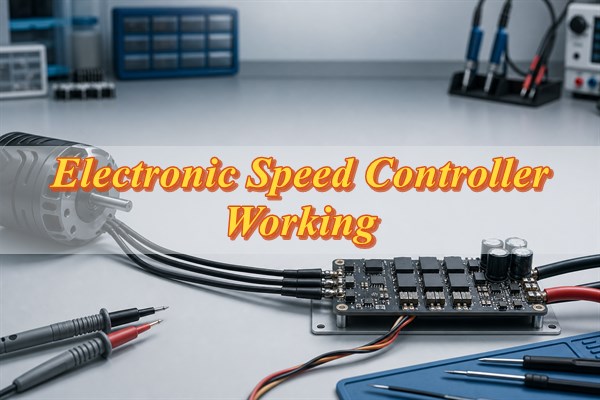
What Does an Electronic Speed Controller Do?
An ESC regulates motor torque and speed by switching electrical power instead of dissipating excess energy like a linear control element. A low-power command arrives from a receiver, flight controller, vehicle controller, or industrial processor. The ESC validates that command and translates it into precisely timed gate signals for the power switches.
In a brushed motor, the mechanical commutator already changes winding polarity, so the controller mainly regulates current through a half bridge or full bridge. In a brushless DC motor, the ESC must also decide which motor phases to energize and when to change the active phase pair. Closed-loop designs may regulate current, torque, or speed; simpler designs mainly control duty cycle and rely on the motor and load to establish the resulting speed.
- Command processing: Decode an analog, pulse-based, digital, or network command and reject invalid or stale data.
- Power conversion: Switch the DC bus through MOSFETs or other power devices with controlled timing.
- Motor commutation: Select the correct winding or phase state to maintain torque in the requested direction.
- Feedback control: Use current, voltage, temperature, speed, or rotor-position data when the design supports it.
- Fault protection: Limit or stop switching when measured conditions exceed defined safe boundaries.
These electronic speed controller working functions make an ESC more than a motor power switch. It is a real-time control system whose signal chain and power path must remain coordinated during startup, acceleration, braking, load changes, and faults.
Which Components Support Electronic Speed Controller Working Principles?
A complete ESC combines an input interface, controller, gate driver, power bridge, sensors, low-voltage supplies, DC-link network, and protection circuits. Each block has a separate task, but a weakness in one block can destabilize the entire controller.
| Circuit block | Primary function | Typical failure risk | Useful verification |
| Input interface | Receive and condition the throttle command | Wrong logic level, noise, lost ground reference | Measure the command at the controller pin |
| Microcontroller | Decode commands, run control logic, manage faults | Timing error, brownout, unsafe reset behavior | Check startup, watchdog, and fault-state transitions |
| Gate driver | Charge and discharge MOSFET gates | False turn-on, inadequate dead time, bootstrap dropout | Probe gate-to-source voltage at the device |
| Power bridge | Route current through motor windings | Shoot-through, avalanche, conduction or switching loss | Observe switch nodes, phase current, and temperature |
| Current, voltage, and temperature sensing | Provide control and protection feedback | Offset, noise, slow response, wrong threshold | Apply calibrated stimuli and verify trip behavior |
| DC link and low-voltage supplies | Stabilize the bus and power logic circuits | Bus ringing, ripple, regulator brownout | Measure rails during startup and load transients |
These electronic speed controller working principles normally require three half bridges, for a total of six controlled switches in a three-phase brushless ESC. Higher-current designs may parallel MOSFETs, but parallel devices do not automatically share current equally. Gate-loop symmetry, copper resistance, source inductance, component tolerance, and temperature gradients affect sharing. PCB layout is therefore part of the electrical circuit: the high-current loop should be short, gate paths should be controlled, sensing should use quiet references, and heat must reach copper or a defined cooling structure.
How Does an ESC Receive and Interpret Throttle Commands?
The ESC first validates the command format and operating state, then converts the requested throttle or torque into an internal control target. The external command is not the same as the high-frequency PWM waveform applied to the power stage.
Traditional RC PWM encodes throttle in pulse width. OneShot uses shorter timing to reduce command latency. DShot sends a digital frame with throttle data and an integrity check, while CAN-based control can carry addressed commands and diagnostic messages over a differential bus. Industrial controllers may instead accept analog voltage, frequency, serial data, or another documented interface.
- Electrical compatibility: Confirm voltage levels, polarity, input protection, ground reference, and connector pinout.
- Protocol compatibility: Match pulse range, frame format, bitrate, update interval, and firmware implementation.
- Arming behavior: Define the required neutral command, startup delay, and conditions that permit motor output.
- Failsafe behavior: Specify what happens when a command is missing, corrupt, out of range, or too old.
- Noise immunity: Keep command traces away from switch nodes and verify the interface while the power bridge is switching.
In electronic speed controller working logic, engineers should test both sides of the signal chain. A valid command at the input proves only that the interface is working; it does not prove that firmware generated the correct commutation state or that the gate driver delivered safe waveforms.
How Do Electronic Speed Controller Working Principles Use PWM to Control Motor Speed?
PWM controls the effective motor voltage or current by rapidly changing the proportion of each switching period for which the power stage is active. The ratio of on-time to total period is the duty cycle. Motor winding inductance smooths the switched voltage into a current waveform, while mechanical inertia further smooths the resulting torque.
At a fixed DC-bus voltage, a higher duty cycle generally increases the voltage available to overcome back electromotive force and winding resistance. That can increase torque and allow speed to rise under load. However, speed is not simply duty cycle multiplied by maximum speed. Battery sag, winding resistance, motor back EMF, load torque, commutation timing, current limits, and control mode all affect the result.
PWM frequency is also a trade-off. A higher frequency can move audible components and reduce current ripple, but it increases switching events and may raise MOSFET and gate-driver losses. A lower frequency can reduce switching loss but increase ripple, noise, and torque pulsation. The appropriate value depends on motor inductance, switch characteristics, gate resistance, thermal design, and acoustic requirements.
Within electronic speed controller working principles, input-command PWM and power-stage PWM have different roles. The first communicates a requested operating point; the second directly controls the bridge. Verification should include command decoding, duty-cycle limits, gate dead time, phase current, switch-node ringing, and thermal behavior under the intended load.
How Does an ESC Commutate Brushless Motor Phases?
A brushless ESC produces continuous torque by energizing the motor phases in a sequence synchronized with rotor position. In common six-step commutation, two phases conduct while the third is inactive or observed. The controller advances through six electrical states as the rotor turns.
A sensored ESC changes states according to Hall sensors or another position device. A sensorless ESC estimates position from motor electrical behavior. Field-oriented control uses rotor angle and current components to command a rotating voltage vector, which can provide smoother torque and better low-speed behavior but requires additional sensing, computation, calibration, and tuning.
Dead time between high-side and low-side transitions is essential because both switches in one half bridge must not conduct simultaneously. Too little dead time risks shoot-through. Too much dead time distorts phase voltage, increases diode conduction, and can reduce control accuracy. Engineers should evaluate dead time at actual temperature and bus voltage because switching delay changes with device, driver, layout, and operating conditions.
Timing advance can improve operation at higher electrical speed, but excessive advance increases current and heat or weakens startup. These electronic speed controller working requirements mean that correct commutation involves more than using the right state table; the controller must switch at the right rotor angle and preserve safe device timing.
How Does a Sensorless ESC Detect Rotor Position?
A sensorless ESC commonly estimates rotor position from back EMF in the temporarily undriven phase, but it cannot rely on that signal at standstill. Back EMF rises with speed, so startup requires a separate alignment and open-loop acceleration process before reliable closed-loop detection becomes possible.
In six-step control, the controller can observe when the floating phase voltage crosses a reference related to the DC-bus midpoint. After filtering and a calculated delay, it advances to the next commutation state. Some designs use comparators; others sample phase voltage with an analog-to-digital converter and process the result in firmware. More advanced observers estimate rotor angle from a motor model and measured voltage or current.
- Low-speed limitation: Weak back EMF makes position detection sensitive to noise and load changes.
- Blanking requirement: Switching transients must settle before the controller trusts a phase-voltage sample.
- Startup requirement: Alignment current and open-loop acceleration must move the rotor without exceeding safe current.
- Load sensitivity: A heavy or rapidly changing load can prevent the rotor from following the forced startup sequence.
- Layout requirement: Phase sensing needs controlled scaling, filtering, and a quiet reference despite high dv/dt nearby.
Sensorless electronic speed controller working performance should therefore be verified across startup load, minimum stable speed, acceleration rate, bus voltage, and motor temperature. A controller that detects position reliably at steady speed may still lose synchronization during a loaded start or abrupt transient.
A sensorless design should be tested across minimum and maximum bus voltage, motor variants, temperature, inertia, and starting load. A successful no-load bench start does not prove reliable startup in the final mechanism.
How Do Brushed, Sensorless, and Sensored ESCs Differ?
The motor construction and required low-speed behavior determine the correct ESC type before current rating or feature count is considered. Brushed, sensorless brushless, and sensored brushless controllers use different bridges and position-feedback methods.
| ESC type | Control method | Advantages | Limitations | Suitable use |
| Brushed | Half bridge or full bridge controls a mechanically commutated motor | Simple control and strong starting behavior | Brush wear, electrical noise, and lower motor life in demanding duty | Simple DC drives and reversible actuators |
| Sensorless brushless | Electronic commutation using estimated rotor position | Fewer motor wires and no position sensor | Startup and very-low-speed operation depend on estimation quality | Fans, pumps, propellers, and loads that can accelerate cleanly |
| Sensored brushless | Electronic commutation using Hall or other position feedback | Predictable startup and better low-speed control | More wiring, connectors, sensor alignment, and interface failure points | Traction, robotics, positioning, and high starting-load systems |
Comparing electronic speed controller working principles shows why sensored and sensorless are not universal quality levels. A well-designed sensorless controller can be ideal for a steadily rotating load, while a sensored controller may be necessary where the motor must start under load or produce controlled torque near zero speed. Bidirectional operation, regenerative braking, field-oriented control, and network communication are separate features that must be confirmed rather than inferred from the ESC type.
Which ESC Voltage, Current, Timing, and Thermal Ratings Matter?
The useful ESC rating is the rating that remains valid at the actual bus voltage, current waveform, cooling condition, switching frequency, and duty cycle. A single current number without test conditions is not enough for design or procurement.
- Bus-voltage range: Include the maximum charged supply voltage and transient overshoot, not only nominal voltage.
- Continuous current: Relate the rating to ambient temperature, airflow, heat sinking, copper area, and allowable temperature rise.
- Peak current: Confirm peak magnitude, permitted duration, repetition rate, and the protection threshold that may interrupt it.
- PWM frequency: Check switching loss, current ripple, acoustic behavior, and gate-driver capability at the selected frequency.
- Commutation timing: Verify startup, timing advance, minimum pulse width, dead time, and maximum electrical speed.
- Thermal limits: Distinguish measured board or case temperature from semiconductor junction temperature.
Electronic speed controller working limits should be evaluated from current waveforms, not just an average value. Acceleration, stall, braking, propeller loading, and commutation errors can produce short peaks that stress MOSFETs, shunts, capacitors, connectors, and copper. Similarly, long battery leads add inductance and can increase DC-bus overshoot. An appropriate design margin must be justified by measurement and component limits rather than a universal percentage.
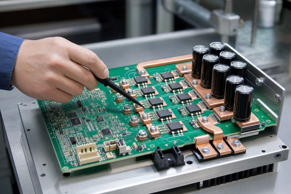
How Do Electronic Speed Controller Working Principles Prevent Overcurrent, Overvoltage, and Overheating?
ESC protection works only when sensors, thresholds, response time, firmware state transitions, and power-device limits are coordinated. A protection feature printed on a specification does not prove that every fault will be interrupted before damage.
Protection is a necessary part of electronic speed controller working principles. Overcurrent protection may use a shunt, current-sense amplifier, comparator, MOSFET on-resistance estimate, or another sensing method. A fast hardware path can respond to severe current events, while firmware can manage slower limiting, retry, or shutdown behavior. The threshold must tolerate normal switching noise without being delayed so much that the power stage exceeds its safe operating area.
Overvoltage management begins with a suitable device rating, low-inductance DC-link capacitors, controlled wiring, and suppression where justified. Regenerative braking can return energy to the supply; if the source cannot absorb it, the bus voltage may rise. Undervoltage protection is equally important because a falling logic or gate-drive rail can leave MOSFETs inadequately enhanced or cause uncontrolled resets.
Thermal protection uses a sensor at a measurable location, but that reading is not identical to the hottest semiconductor junction. Sensor placement, thermal lag, airflow, copper spreading, and switching loss affect the difference. A safe design validates the trip and recovery behavior under representative cooling and load conditions.
- Fault response: Define whether the ESC limits output, shuts down, latches off, or retries.
- Restart control: Prevent an unexpected motor restart after power, command, or temperature recovers.
- Sensing integrity: Check offset, tolerance, filtering, open-sensor behavior, and noise at worst-case switching.
- Protection boundary: State which faults are covered and which require a fuse, contactor, supply limit, or system-level safeguard.
How Can You Test and Troubleshoot ESC Desynchronization and Other Faults?
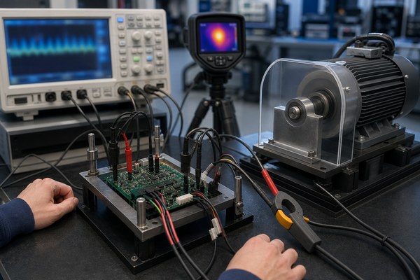
ESC troubleshooting should separate command, power, commutation, sensing, thermal, and mechanical causes instead of replacing parts at random. Begin with a current-limited, guarded setup and a known compatible motor and supply.
- Inspect the hardware: Check polarity, connectors, solder joints, MOSFETs, capacitors, shunts, and sensor wiring before applying power.
- Verify control power: Measure the low-voltage rails, reset state, and gate-driver supply with the motor disabled.
- Confirm the command: Check the throttle signal at the controller input and test loss-of-signal behavior.
- Measure gate drive: Probe gate-to-source waveforms at the MOSFET pins and check amplitude, dead time, ringing, and false turn-on.
- Observe the power stage: Record DC-bus voltage and phase current during startup, acceleration, steady load, and commanded braking.
- Check rotor feedback: Verify phase sensing, Hall transitions, or back-EMF sampling according to the control method.
- Track temperature: Record component and board temperatures until they stabilize or the defined test limit is reached.
- Verify protection: Inject permitted faults individually and confirm threshold, response, latch or retry behavior, and safe recovery.
A disciplined electronic speed controller working diagnosis correlates command timing, gate signals, bus voltage, phase current, rotor feedback, and temperature on the same test timeline. This prevents a downstream symptom, such as overcurrent shutdown, from being mistaken for the original cause.
Desynchronization occurs when commanded commutation no longer matches rotor position. Understanding the electronic speed controller working principles helps separate excessive load, aggressive acceleration, incorrect timing, weak sensorless back EMF, noisy phase sensing, current limiting during startup, supply collapse, and unsuitable motor parameters. The next action should follow the evidence: compare phase-current symmetry, command timing, rotor feedback, bus stability, and thermal state immediately before the loss of synchronization.
Shoot-through produces abnormal current when both switches in one half bridge conduct together. Check gate overlap, Miller-induced false turn-on, driver supply integrity, common-source inductance, and gate-loop layout. Intermittent shutdown may instead indicate overtemperature, undervoltage, command timeout, connector resistance, or an overly sensitive protection threshold.
How Do You Match an ESC to a Motor and Power Supply?
Match the ESC by motor type, bus-voltage envelope, real current demand, control interface, startup load, braking behavior, cooling, and verification evidence. Choosing only by an advertised ampere rating can leave important compatibility risks unresolved.
- Identify the motor: Confirm brushed or brushless construction, phase count, sensor type, pole count, winding characteristics, and allowable speed.
- Define the supply: Record nominal and maximum voltage, current limit, internal resistance, cable length, polarity protection, and ability to absorb regenerative energy.
- Estimate the load: Include startup, acceleration, stall or jam risk, continuous torque, inertia, propeller or pump behavior, and braking duty.
- Match control features: Confirm command protocol, direction control, telemetry, current control, braking, firmware settings, and failsafe behavior.
- Check thermal conditions: State ambient temperature, enclosure, airflow, heat-spreader interface, mounting, and expected duty cycle.
- Request evidence: Obtain rating conditions, protection thresholds, connector limits, firmware documentation, and representative test results where available.
Applying electronic speed controller working principles requires treating the motor, ESC, and supply as one dynamic system. A supply with excessive cable inductance can create bus overshoot; a supply with aggressive current limiting can collapse during startup; and a motor with low inductance can produce high ripple at an unsuitable PWM frequency. Final acceptance should therefore use the intended motor, supply, wiring, load profile, cooling arrangement, and firmware configuration.
For a custom controller, provide the manufacturing partner with the schematic, layout data, Gerber or ODB++ package, bill of materials, stackup, current and thermal requirements, assembly notes, firmware or programming requirements, and test plan. The PCB and PCBA documentation should preserve low-inductance power loops, controlled gate paths, sensing integrity, copper balance, insulation spacing, solder-joint quality, and traceability.
FAQs About Electronic Speed Controller Working Principles
Q1: Does an ESC directly set motor RPM?
A1: Not always. A basic controller mainly sets duty cycle or commutation output, so speed still changes with load and supply voltage. Accurate RPM regulation requires speed feedback and a closed-loop controller.
Q2: Can one ESC operate both brushed and brushless motors?
A2: Usually not. The required bridge and commutation logic are different. Use an ESC explicitly designed for the motor construction, unless its documentation clearly supports both modes.
Q3: Why does an ESC beep through the motor?
A3: Many ESCs switch the motor windings at an audible pattern during startup or status reporting. The motor acts as the sound-producing element. Beep meanings depend on the specific firmware, so use its documented code table.
Q4: What is ESC calibration?
A4: Calibration commonly teaches a pulse-based ESC the controller’s minimum and maximum command endpoints. Digital protocols may not require endpoint calibration, but arming and direction settings still need verification.
Q5: Can a higher-current ESC damage a motor?
A5: The rating alone does not force current into the motor. However, permissive current limits, unsuitable timing, excessive voltage, or poor setup can allow damaging current. The control limits and supply must match the motor.
Q6: Why does an ESC reset when the motor starts?
A6: Startup current may pull down the battery, connector, or logic supply, or switching noise may disturb reset circuitry. Measure the DC bus and logic rails during the event before changing firmware.
Q7: What is active freewheeling or synchronous rectification?
A7: The controller turns on a MOSFET to carry recirculating current instead of relying only on its body diode. It can reduce conduction loss, but it requires safe timing to avoid shoot-through.
Q8: Can an ESC provide regenerative braking?
A8: Only if the hardware, firmware, and power source support energy returning to the DC bus. A battery or supply that cannot absorb returned energy may experience overvoltage.
Q9: Is a cold ESC proof that its MOSFET junctions are safe?
A9: No. External temperature can lag the semiconductor junction and may miss a local hotspot. Use a justified thermal path and temperature estimate under steady and transient load.
Q10: What production tests are useful for a custom ESC PCBA?
A10: Useful coverage may include visual or automated optical inspection, rail checks, programming verification, command-response checks, guarded motor operation, current measurement, and protection tests. The test plan must match the design risks and acceptance limits.
A reliable ESC must do more than spin a motor on a bench. It must interpret commands correctly, switch the required phases without shoot-through, regulate current through PWM, maintain rotor synchronization, and respond predictably to electrical and thermal faults. Selection is complete only when the motor, power supply, wiring, cooling, control protocol, protection behavior, and operating load have been verified together.
For custom ESC PCB or PCBA manufacturing, contact EBest Circuit at sales@bestpcbs.com for a quotation. Please submit your Gerber or ODB++ files, BOM, order quantity, stackup, assembly requirements, firmware programming files, and test requirements so the engineering team can review manufacturability and verification needs.