An electronic device performs a particular job: a diode steers current, a resistor limits it, and a transistor can switch a load. An electronic circuit connects devices so they do a job together. One diode is a device; four diodes arranged in a bridge make a circuit that turns both halves of an AC waveform into current flowing in one direction through a load.
This guide explains the common parts and the circuits they form, then follows a 5 V LED indicator from calculation through assembly and testing. You do not need a PCB to try the example.
electronic devices and circuits
Read a device datasheet to learn what a part can do. Read the schematic to see what it is meant to do in the circuit. An LED datasheet describes forward current and voltage, for example, but the supply and the series resistor determine the operating current. The printed circuit board (PCB) implements the schematic connections; after components are fitted and soldered, the result is a printed circuit board assembly (PCBA). A prototype can use a breadboard first.
electronic circuit components and their functions
Start by asking what each part does to energy or a signal. Passive parts can dissipate, store, or transfer energy. Powered active circuits can use energy from a supply to amplify a signal. A diode is a semiconductor device but does not itself supply power gain.
| Part | Function | Check |
| Resistor | Limits current or sets voltage | Ω, tolerance, watts |
| Capacitor | Stores energy in an electric field | Voltage, effective C |
| Inductor | Stores energy in a magnetic field | Current, saturation |
| Diode | Conducts mainly one way | Forward drop, reverse rating |
| Transistor | Switches or controls current | Drive, loss, temperature |
| Op-amp | Amplifies an input difference | Input range, output swing |
A nominal value rarely tells the full story. For example, the effective capacitance of some ceramic capacitors falls under DC bias. Check the manufacturer’s data at the operating voltage rather than using only the number on the schematic.
semiconductor devices
A semiconductor device controls the movement of charge carriers. In n-type material electrons are the majority carriers; in p-type material holes are. Joining the regions forms a PN junction with a depletion region. Forward bias lowers the junction barrier and increases current; reverse bias normally permits only leakage until breakdown. A silicon diode does not have one fixed forward voltage: read it at the intended current and temperature.
Silicon is common in diodes and integrated circuits. Silicon carbide and gallium nitride are also used in power devices, but the material name is not a substitute for checking the exact voltage, switching, and thermal ratings.
ohm law formula
Use V = I × R for an ohmic resistor: volts, amperes, and ohms. Across 1 kΩ, an ideal 5 V supply drives 5 mA and the resistor dissipates 25 mW. For resistor power, use P = V × I, I²R, or V²/R. Across a diode, use its current–voltage behavior instead of treating it as a fixed resistance.
Kirchhoff’s current law says the signed currents at a node sum to zero; the voltage law says the signed voltages around a lumped-circuit loop sum to zero. In the LED example below, one current flows through both parts, and the resistor and LED voltage drops add to the supply voltage. With AC signals, ideal capacitive reactance is 1/(2πfC), and ideal inductive reactance is 2πfL.
diode rectifier circuit
A half-wave rectifier sends only one half-cycle through the load. A full-wave bridge sends both half-cycles through it in the same direction, using a different pair of diodes on each half-cycle. Two diode drops are in the conducting path of a typical bridge. The output is pulsating DC before filtering.
| Option | Ripple frequency | Trade-off |
| Half-wave | Input frequency | One diode; longer recharge gap |
| Full-wave bridge | Twice input frequency | Four diodes; two conduct at a time |
A smoothing capacitor charges near waveform peaks and supplies the load between them. Output ripple depends on load current, capacitance and recharge interval. For a learning build, use a suitable isolated low-voltage source rather than a mains-connected circuit.
bjt vs mosfet
Choose by drive and operating point. A bipolar junction transistor (BJT) needs base current. In forward-active operation, collector current is approximately β times base current, but β varies and that relation is not a saturated-switch guarantee. A metal-oxide-semiconductor field-effect transistor (MOSFET) uses gate-to-source voltage, and its driver must charge and discharge the gate.
| Check | BJT | MOSFET |
| Switch drive | Base current | Gate voltage and charge |
| Conduction loss | On-state drop × current | Current² × on-resistance |
| Datasheet item | Saturation conditions | RDS(on) at actual drive |
If a 3.3 V controller drives a MOSFET, a threshold below 3.3 V is not enough. The threshold is specified at a small test current. Look for on-resistance data at the actual drive voltage, check temperature, then measure the voltage drop and heating under load.
analog and digital circuits difference
Analog circuits work with continuously varying signal values; digital circuits interpret signals as discrete states. A temperature sensor illustrates both: an analog filter reduces noise before the converter, and a microcontroller then compares the digital reading with a threshold to decide whether to light the indicator.
An ideal non-inverting amplifier has gain 1 + Rf/Rg; 9 kΩ and 1 kΩ yield a gain of 10 if the amplifier has enough bandwidth and output swing. A first-order RC low-pass filter with 1 kΩ and 100 nF has an approximate cutoff of 1/(2πRC) = 1.59 kHz when source and load effects are negligible. An oscillator instead generates a repeating signal, such as a clock. On the digital side, an AND gate needs all inputs high; a flip-flop can retain a state after the input changes. Check logic thresholds and timing, not just the nominal supply voltage.
linear vs switching regulator
A linear regulator can be a simple choice when heat and voltage headroom allow it. In an illustrative 12 V to 5 V design at 0.5 A, the pass element dissipates about (12 − 5) × 0.5 = 3.5 W, ignoring quiescent current. Check the actual thermal path before committing. A buck switching regulator may reduce heat at the same load, but check output ripple, transient response, and the layout of the switching-current loop. Boost steps up DC; buck-boost designs can operate across input ranges above and below the output, depending on topology.
led resistor calculation
Subtract the LED forward voltage from the supply voltage, then divide by the target current. For a 5 V supply, assumed 2.0 V red LED and target 10 mA, the result is (5 − 2)/0.010 = 300 Ω. Choosing 330 Ω reduces the nominal current to about 9.09 mA and the resistor loss to about 27 mW. A 0.125 W resistor has nominal margin for this example; confirm its temperature derating and the LED’s limits for the real build.
| Parameter | Teaching value | Verify on the bench |
| Supply | 5.0 V DC | Voltage under load |
| LED drop | 2.0 V assumed | Voltage and polarity |
| Series resistor | 330 Ω | Actual value or tolerance |
| Current | 9.09 mA nominal | Resistor drop ÷ resistance |
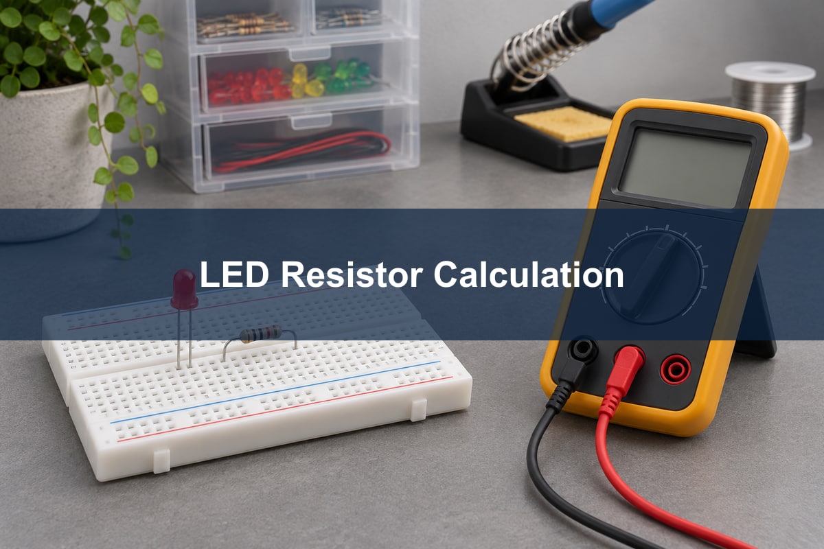
- With power off, connect the resistor and LED in series between 5 V and return, with the LED cathode toward return. Check the specific part’s polarity and the breadboard row connections.
- Power the prototype from a current-limited 5 V source. Measure the voltage across the resistor and divide it by its resistance. Around 3 V across 330 Ω gives about 9.1 mA.
- For a tolerance check, recalculate maximum current with the highest supply voltage, lowest plausible forward voltage, and lowest resistance. At the other corner, verify brightness at the lowest expected current.
pcb design process
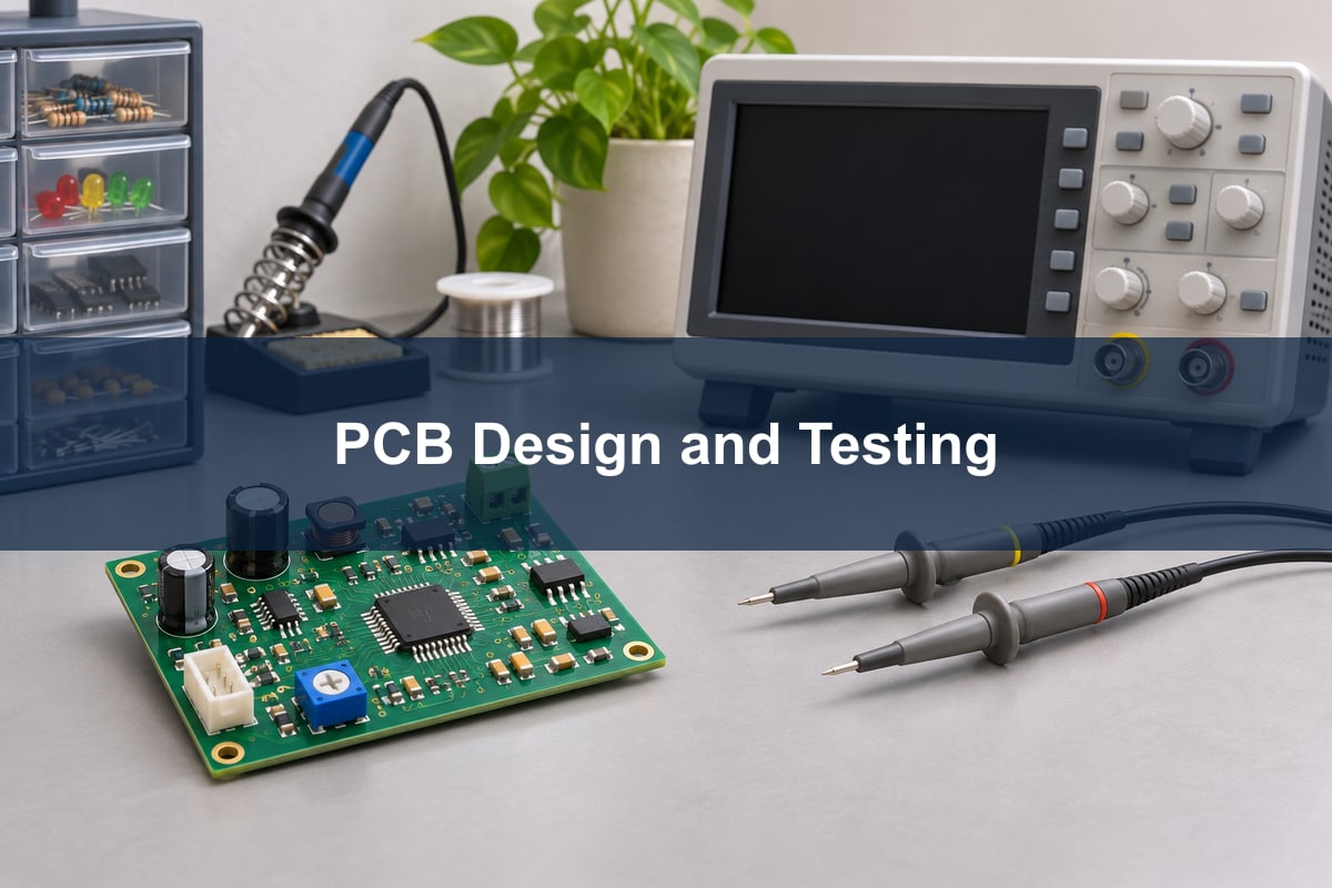
A schematic specifies connections; PCB layout decides where those connections and components actually go. For the indicator, start with the LED position and visibility, verify the footprint and cathode marking, and leave room to probe the supply and resistor. For faster or higher-current circuits, also check current return paths, trace geometry, decoupling and heat dissipation.
Fabrication produces the bare board. Assembly fits and solders parts by surface-mount or through-hole methods. Inspection and testing then answer different questions: automated optical inspection (AOI) can see placement and visible joints; X-ray can inspect hidden joints; functional testing checks the assembled circuit against its intended behavior. Match the test plan to the failure you need to catch.
electronic circuit troubleshooting
Measure power before tracing signals. If the indicator is dark, check 5 V at the board under load, then measure the resistor drop. Nearly zero drop suggests little current; check polarity, open connections, or the wrong breadboard row. If the resistor takes nearly the full supply voltage, look for an unintended bypass around the LED. Disconnect power before continuity or resistance tests.
On a mixed-signal board, compare the expected and actual voltage or waveform at successive stages. A steady rail does not rule out short transients; use an oscilloscope when symptoms coincide with switching or load changes. Change one thing at a time and rerun the same test so you can tell whether the correction worked.
FAQ
What are the five basic electronic components to learn?
Start with the resistor, capacitor, inductor, diode, and transistor. They are not an exhaustive list. Learn how each behaves with a source and a load, then add sensors, switches, and integrated circuits as a design calls for them.
Can I test a circuit without making a PCB?
Yes. A solderless breadboard works for many low-voltage, low-speed experiments. If the behavior depends on short loops, controlled impedance, or repeatable grounding, a breadboard may not predict the finished PCB’s behavior.
Does the LED resistor go before or after the LED?
Either position works in one series branch because the same current flows through both parts. Put the resistor in series, not across the LED. Keep the LED polarity correct.
Can I use one resistor for several parallel LEDs?
Prefer a separate resistor per parallel branch. Small forward-voltage differences can make one LED draw more of the current if all branches share one resistor.
Why does a MOSFET switch heat up even though it turns on?
It can conduct at threshold without being fully enhanced. Check the actual gate-to-source voltage, on-resistance at that drive, and the switching waveform under load before choosing a replacement.
Is a rectifier the same as a voltage regulator?
No. A rectifier makes current unidirectional through the load; a regulator controls its output voltage within operating limits. A power supply may use both, with filtering in between.
Can a digital circuit still have analog problems?
Yes. Logic states are represented by real voltages and timing. Noise, slow transitions, or a poor return path can shift the receiver’s threshold crossing and produce errors.
What files are needed to quote an assembled board?
Provide the released fabrication data, bill of materials, component placement file, assembly drawing, quantity, and required test criteria. Keep all files on the same revision and identify any parts with restricted substitutions.
References
- OpenStax: Direct-current circuits and Kirchhoff’s rules
- OpenStax: RC circuits
- Texas Instruments: CSD16323Q3 datasheet, example MOSFET test conditions
If your prototype is ready for fabrication or assembly review, send the project files and test requirements to Best Technology at sales@bestpcbs.com.