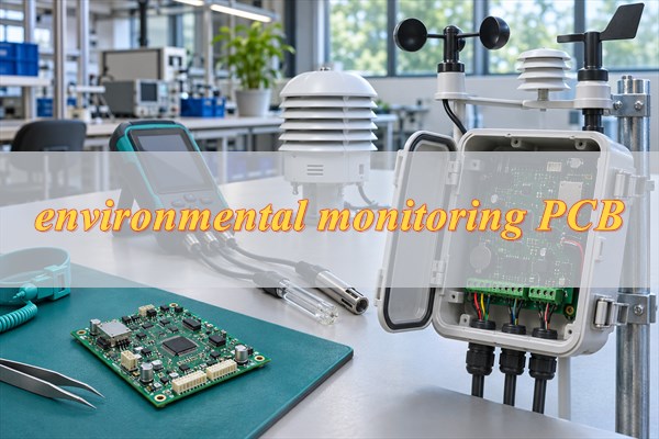
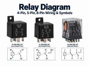
An electronically controlled automatic chemical dosing system regulates chemical addition according to a programmed schedule, process flow, or measured water condition. Behind the pump and display, its circuit boards handle measurement, control signals, power distribution, and communication. Reliable operation depends on these functions working together without pump switching disturbing sensitive sensor readings.
At EBest Circuit, we combine PCB fabrication with component sourcing and SMT/THT assembly, helping dosing-equipment developers coordinate the manufacture of their control electronics. Mixed assembly accommodates compact signal-processing components alongside larger connectors and relays. For your next controller build, contact sales@bestpcbs.com or visit Contact Us, scroll to the bottom, and fill in the contact form.
What Is a Chemical Dosing System?
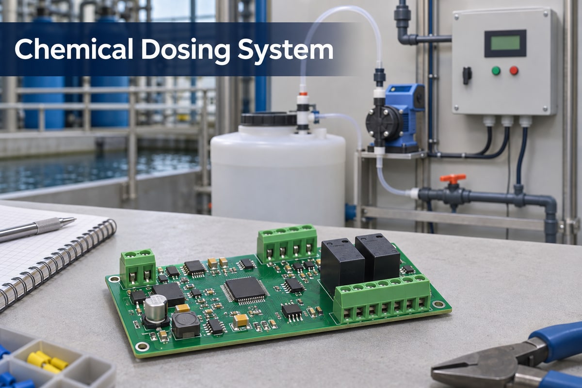
A chemical dosing system stores, meters, and introduces a controlled quantity of chemical into a process. It may operate with manual settings, electronic controls, or a water-powered proportional mechanism. This article focuses on the PCBs used in electronically controlled equipment.
A chemical dosing system for water treatment can serve several distinct purposes.
- Disinfection introduces chemicals such as sodium hypochlorite to support microbial control.
- pH adjustment adds acid or alkali to move the process toward its target pH.
- Coagulation and flocculation support the separation of suspended material during treatment.
- Scale and corrosion control delivers treatment chemicals to help protect water-system equipment.
These applications do not all use the same feedback signal. A pH-control loop measures pH, while flow-paced dosing follows water throughput. The treatment objective therefore shapes the controller’s inputs and operating logic.
The dosing pump is one part of that system. Storage equipment, tubing, injection fittings, measurement devices, and controls complete the installation. A pump can deliver liquid at a selected rate, while the wider system determines when dosing is needed and how the equipment responds to changing conditions.
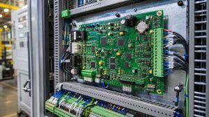
The electronics also vary with the equipment architecture. A plant installation may use a PLC with separate instruments; a compact dosing controller may use a custom PCB containing processing, input, output, and display functions. One circuit board does not replace the complete hydraulic system.
Chemical Dosing System Diagram: Main Components and Connections
A simplified chemical dosing system diagram contains two connected paths. The fluid path carries the chemical; the signal path determines the pump command.
Chemical path
Chemical tank → Metering pump → Injection point → Process stream
Control signal path
Flowmeter or water-quality instrument → Controller → Pump control input
In a feedback installation, a measurement taken after an appropriate mixing and response interval returns to the controller. Tank-level switches, process-flow signals, and equipment alarms can provide additional inputs.
An important electrical distinction sits between the controller and pump. A controller may send a low-power command to a pump with its own drive electronics. Alternatively, an integrated pump controller may contain the power stage that operates a motor or solenoid. These arrangements require different output components, copper layouts, and thermal provisions.
How Does an Automatic Chemical Dosing System Work?
In an electronically controlled automatic chemical dosing system, the controller converts an operating requirement into a pump command. The controller reads the relevant input, applies the configured dosing logic, and adjusts the output. Automation can follow process flow or a timer without measuring the resulting chemical concentration.
For flow-proportional dosing, the required active-chemical mass rate follows a simple relationship when the target dose is expressed in mg/L and water flow in m³/h.
Active chemical required (g/h) = Water flow (m³/h) × Target dose (mg/L)
For example, a hypothetical water flow of 10 m³/h and target addition of 2 mg/L require 20 g/h of active chemical. With a stock solution containing 100 g/L of that active chemical, the theoretical solution feed is 0.2 L/h. This is a mass-balance illustration, not a treatment recommendation or a pump accuracy specification. Actual delivery also depends on solution concentration, pump calibration, and operating conditions.
Feedback control adds another step. It compares a measured value with a setpoint and changes the command in response. The ProMinent DCM 5 controller family, for example, includes proportional and PID control strategies and configurable flow-related interlocks. Those functions illustrate how measurement, control, and equipment status can work together; they are not universal features of every dosing controller.
Manual vs. Flow-Proportional vs. Feedback Dosing Control
These methods differ in what causes the dosing command to change. Flow-proportional control responds to throughput, while feedback control responds to the measured process result.
| Control method | Basis for dosing | Response to change | Main limitation |
|---|---|---|---|
| Manual setting | Operator-selected feed rate | Changes when the operator adjusts it | Does not automatically follow changing flow or chemical demand |
| Flow-proportional | Process flow and a configured dose ratio | Increases or decreases feed with throughput | Does not directly measure the resulting water quality |
| Feedback | Measured parameter compared with a setpoint | Adjusts feed as the measured result changes | Depends on sensor condition, mixing, response delay, and tuning |
A system can also combine flow pacing with feedback correction. This allows the flow signal to establish the basic feed rate while the measurement refines the command. In an electronic implementation, the PCB must support the required inputs and outputs, but the control performance still depends on the complete instrument and process. Water-powered proportional dosing can instead use a hydraulic mechanism without electronic metering control.
Which PCB Modules Support a Chemical Dosing Pump System?
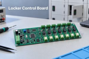
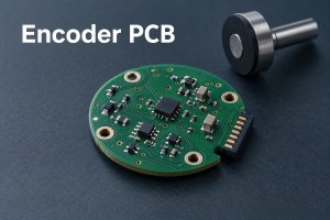
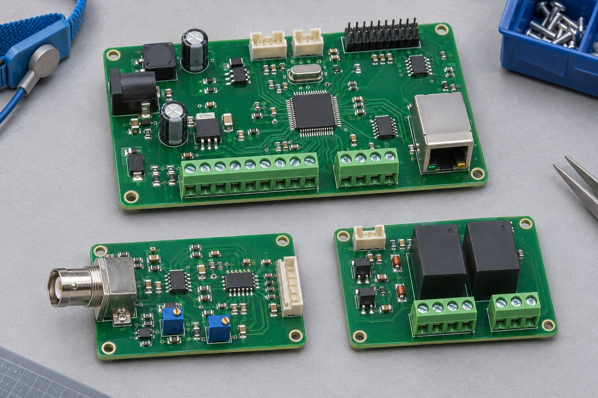
An electronically controlled chemical dosing pump system may use separate boards or combine several functions on one assembly. The division follows enclosure space, electrical noise, service access, and the pump architecture.
- Sensor interface board conditions measurement signals before conversion or communication. A direct pH-probe input needs a different front end from an input receiving a conditioned industrial transmitter signal.
- Main control board processes inputs, runs firmware, stores settings, and handles alarms or operating states.
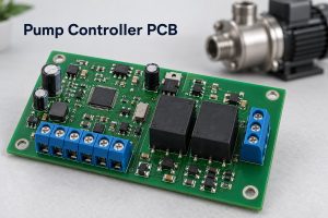
- Pump interface or driver board either sends a command to an external pump or supplies controlled power to the actuator. A signal output and a motor drive are not interchangeable.
- Display and communication board connects the operator interface and external equipment, allowing readings, settings, and operating status to be exchanged.
- Power-supply section provides the voltage rails needed by logic, analog circuits, communication interfaces, and output stages.
Separating a sensitive measurement section from a noisy output stage can simplify layout. Combining them can reduce connectors and assembly space. Neither approach automatically gives better performance; the electrical arrangement and implementation determine the result.
Chemical Dosing System Design: Sensor Interfaces, Pump Outputs, and PCB Protection
Chemical dosing system design brings sensitive measurements and switching outputs into the same equipment. The PCB layout must preserve the measurement signal while carrying the required power and external connections.
Sensor interfaces and leakage control
A glass pH electrode has a high source impedance. Input bias current and leakage can therefore produce measurement errors. Short, carefully guarded input paths, suitable insulation, and controlled board cleanliness are important around the analog front end. Analog Devices’ CN0326 reference circuit demonstrates a buffered, isolated pH interface with temperature compensation; it is a circuit example, not a specification for all dosing boards.
A board receiving a 4–20 mA transmitter signal requires a different input circuit. For an illustrative 100 Ω shunt, 4–20 mA produces 0.4–2.0 V, with 40 mW dissipated at 20 mA. Resistor tolerance, temperature drift, input protection, and the ADC range remain part of the measurement design.
Pump outputs and current paths
Relay contacts, analog commands, pulse outputs, and motor-drive stages impose different loads. Copper width and thickness follow current and temperature-rise requirements. Output switching loops should be kept away from sensitive inputs, with return paths and transient suppression designed for the actual circuit. A fine-line manufacturing limit is not an appropriate spacing rule for a high-voltage or high-current section.
Protection and service access
Moisture and chemical exposure require attention to the enclosure, cable entries, connectors, and PCB assembly. Conformal coating may form part of the protection scheme, but chemistry, masking, cleanliness, and repair requirements must be specified together. It does not make an assembly waterproof or establish an enclosure IP rating.
Test access also matters. Accessible points for power rails, sensor simulation, output commands, and communication can make board-level verification more repeatable before the controller is installed in the complete dosing system.
EBest Circuit’s PCB Manufacturing and Assembly for Dosing Equipment
We manufacture FR-4 PCBs and provide PCB assembly for customer-defined electronics. For dosing control boards, fabrication planning connects routing density, connector fit, board thickness, and assembly requirements.
| Manufacturing item | EBest Circuit capability |
|---|---|
| FR-4 layer count | 1–10 layers in the regular range; higher-layer builds up to 32 layers under special processing |
| Minimum trace/space with 1 oz copper | 4/4 mil regular; 3/3 mil special |
| Minimum finished hole | 0.20 mm regular; 0.15 mm special |
| Through-hole aspect ratio | Up to 8:1 regular; 10:1 special |
| Four-layer board thickness | Regular minimum 0.6 ± 0.1 mm; thinner builds require special review |
| ENIG finish | Nickel 3–8 µm; gold 0.025–0.125 µm |
| Assembly methods | SMT, THT, and mixed assembly |
These are process capabilities, not a single recommended dosing-board specification. Copper weight, stackup, hole geometry, finish, and assembly requirements must be compatible within the same build. Special limits are evaluated individually rather than combined into an automatic production promise.
Our assembly workflow includes DFA checks, incoming component inspection, SMT/THT processing, AOI, and X-ray inspection where applicable. Functional testing is arranged around the agreed procedure and equipment. A dosing-board test plan can cover input response, output switching, and communication; process dosing accuracy still requires system-level validation.
FAQs About Chemical Dosing Systems
Can a PCB revision improve dosing accuracy?
It can address electrical contributors such as noise, leakage, unstable references, or output errors. It cannot independently correct poor mixing, an unsuitable pump, or a drifting probe. The improvement depends on the cause of the error and must be measured.
Does a dosing controller need recalibration after replacing its PCB?
The equipment’s service procedure determines this. Calibration constants may be stored on the replaced board, and the new analog signal path may have different offsets. Calibration and output operation should be verified before the controller returns to service.
Can one board control several dosing pumps?
Yes, if it has the necessary independent channels, processing resources, power capacity, and interlocks. The number of connectors alone does not establish how many pumps can be controlled simultaneously.
Why can a controller reading change when the pump starts?
Possible electrical causes include a supply-voltage dip, ground-voltage changes, or switching interference entering the sensor circuit. Comparing readings with the output inactive and active helps distinguish electrical interference from an actual process change.
Can a dosing controller use customer-supplied components?
Yes. EBest Circuit offers consignment, partial turnkey, and full turnkey assembly. This allows an equipment developer to supply selected components while arranging the remaining production scope with us.
What determines the lead time for a custom dosing PCBA?
PCB construction, component availability, assembly complexity, programming, and test readiness all affect the schedule. A quoted assembly period should be distinguished from the complete procurement, fabrication, and delivery timeline.
An electronically controlled automatic chemical dosing system depends on electronics that connect measurement to dependable control. EBest Circuit brings FR-4 fabrication, component sourcing, mixed assembly, and agreed inspection and testing into a coordinated production service, reducing handoffs between board manufacture and assembly. Discuss your controller project at sales@bestpcbs.com, or visit Contact Us and complete the form at the bottom of the page.