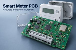
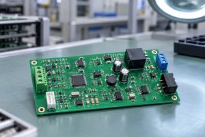
A digital instrument cluster presents driving information through an electronic display, bringing speed, vehicle status, warnings, and other data into the driver’s line of sight. Behind the screen, its PCB connects processing, power management, communication, and display circuits. The finished instrument depends on those circuits working together through startup, changing operating conditions, and repeated use.
EBest Circuit helps engineers move digital instrument cluster boards from design review to prototype and production. Our R&D and PCB/PCBA engineers with 20 years of experience provide DFM pre-review reports, BOM optimization recommendations, and process guidance for multilayer stackups, display connectors, and assembly requirements. With sample and small-batch support, you can evaluate your hardware before scaling production. Visit Contact Us and complete the form at the bottom of the page to discuss your design and request an engineering review.
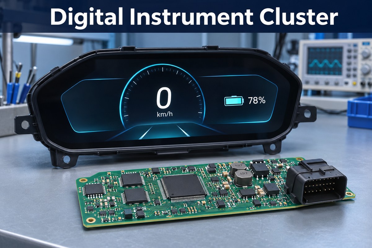
What Is a Digital Instrument Cluster and How Does It Work?
A digital instrument cluster converts vehicle information into readable graphics, numbers, and warning indicators. A full digital cluster displays the main instruments on a screen, while a hybrid cluster combines physical gauges with a digital information area.
Its operation follows four main steps.
- Receive vehicle signals. Sensors and vehicle control modules supply data through input circuits or communication interfaces.
- Interpret the data. The processor and firmware convert incoming values into the readings and status information required by the instrument.
- Update the display. The display system presents changing readings, graphics, and indicators in the appropriate areas of the screen.
- Manage warnings and missing signals. Firmware determines which alerts appear and how the instrument responds when information becomes invalid or unavailable.
The displayed information depends on the vehicle.
- Combustion-engine vehicles may show engine RPM, fuel level, coolant temperature, and oil-pressure warnings.
- Electric vehicles may emphasize battery state of charge, drive power, charging status, and estimated range.
The cluster also needs a defined response when data stops arriving. For example, a lost speed message should trigger the specified warning or unavailable-data indication rather than leave an old reading on screen indefinitely. Available functions depend on the vehicle’s sensors and control system.
Analog vs Digital Instrument Cluster — What Are the Key Differences?
The main difference is how information is presented and how much the presentation can change. Analog clusters use physical pointers and fixed scales. Digital clusters generate their primary instruments on a display. Hybrid designs combine both approaches.
An analog-looking dial does not necessarily mean a purely mechanical system. Many pointer-based clusters already use electronic controllers and electrically driven gauges.
| Feature | Analog cluster | Hybrid cluster | Full digital cluster |
|---|---|---|---|
| Main presentation | Physical pointers and fixed scales | Pointers plus a digital information area | Screen-rendered gauges and information |
| Layout flexibility | Limited by physical dial arrangement | Flexible within the display area | Multiple layouts possible within the hardware and software design |
| Hardware emphasis | Gauge drivers, illumination, inputs | Gauge circuits plus display electronics | Processor, display interface, memory, power and backlight circuits |
| Information capacity | Fixed gauges and indicators | Additional messages and menus | Multiple information views, graphics and contextual warnings |
| Verification focus | Gauge movement, calibration and indicator operation | Both gauge and display behavior | Startup, graphics, data handling, warnings and display behavior |
A full digital design provides more presentation freedom, but adds graphics, software, and display-system requirements. A hybrid instrument can suit an application that needs clear primary readings and a smaller area for additional information. The appropriate architecture depends on the functions the instrument must deliver, rather than screen size alone.
What Hardware Drives an Instrument Cluster Display?
An instrument cluster display is driven by a processor, display interface, power circuits, and the supporting memory and communication hardware required by the application. These functions may share one PCB or be distributed between a main board and a display module.
Processing and memory
The processor interprets vehicle data and generates the display content. A relatively simple instrument can use an MCU with suitable display support. More complex graphics may require a more capable processor, additional memory, and greater memory bandwidth. Those choices influence component packaging, routing density, and power demand.
Display and backlight circuits
The display interface carries image data to the panel. The connection may use a parallel interface or a serialized link, depending on the processor and display module. For a backlit LCD, the backlight driver controls illumination separately from the image data.
Sunlight readability also depends on the panel, optical stack, reflections, and enclosure. Increasing backlight output alone does not resolve every visibility problem and can add heat and power consumption.
Power and vehicle interfaces
Input protection and voltage conversion supply the processor, memory, communication devices, and display circuits. Vehicle interfaces may include CAN, LIN, or direct sensor inputs, according to the architecture.
On the PCB, these circuits need suitable return paths, decoupling, and separation from sensitive signals. Multilayer construction provides routing and reference-plane options, while the actual stackup depends on the package escape routing, interfaces, and mechanical envelope. More layers do not automatically make an instrument better.
How Does an Electric Vehicle Instrument Cluster Handle Vehicle Data?
An electric vehicle instrument cluster receives information from vehicle controllers and sensors, interprets it using the platform’s signal definitions, and presents it to the driver. The exact data sources and displayed functions vary between vehicle designs.
Typical data sources serve different purposes.
- Battery management system — Provides battery information such as state of charge and battery-related warnings, depending on the system architecture.
- Vehicle and motor controllers — Supply operating information that can include speed, drive power, operating mode, and fault status.
- Dedicated sensors and switches — Provide direct inputs where required, such as speed pulses, switch states, or analog sensor signals.
An electric two-wheeler may use a compact display for speed, battery charge, operating mode, and faults. A more complex vehicle may also show charging information, energy consumption, and estimated range. Range estimates can come from another controller; they do not have to be calculated inside the cluster.
Three interface details determine whether the data can be used correctly.
- CAN message interpretation. The firmware must match the vehicle’s message identifiers, data scaling, update timing, and fault-handling rules. A CAN transceiver provides the electrical interface, but does not make the board compatible with every vehicle.
- Direct-input conditioning. Pulse, switch, and analog inputs need circuits that match their electrical characteristics before the processor can use them.
- Power-state coordination. Sleep, wake-up, and shutdown behavior must make the display available when needed while limiting current draw during parking.
PCB Manufacturing and Assembly Capabilities for Automotive Digital Instrument Cluster Projects
EBest Circuit provides FR4 PCB fabrication and component assembly for instrument electronics. The board structure is matched to the processor package, display connections, power circuitry, and enclosure requirements.
The following fabrication capabilities are relevant to multilayer instrument PCB projects. They describe manufacturing ranges, not a mandatory specification for every cluster.
| Fabrication item | Standard capability | Special-process capability or condition |
|---|---|---|
| FR4 layer count | 1–10 layers | 10–32 layers, subject to stackup review |
| High-Tg FR4 options | Tg 170–180°C material options | Material selection follows the application and construction |
| Finished thickness with ENIG | 0.4–3.5 mm | Other thicknesses require process review |
| Minimum finished hole diameter | 0.20 mm | 0.15 mm |
| Maximum through-hole aspect ratio | 8:1 | 10:1 |
| Outer-layer trace width/spacing at 1 oz copper | 4/4 mil | 3/3 mil |
| ENIG finish thickness | Gold 0.025–0.125 µm; nickel 3–8 µm | Specified within the agreed finish requirements |
These limits are not automatically available in every combination. For example, a small finished hole combined with a thick board may exceed the supported aspect ratio. Trace spacing also changes with copper thickness, so the 1 oz figures should not be applied to a heavier-copper design.
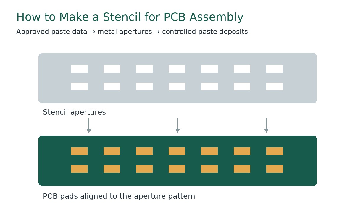
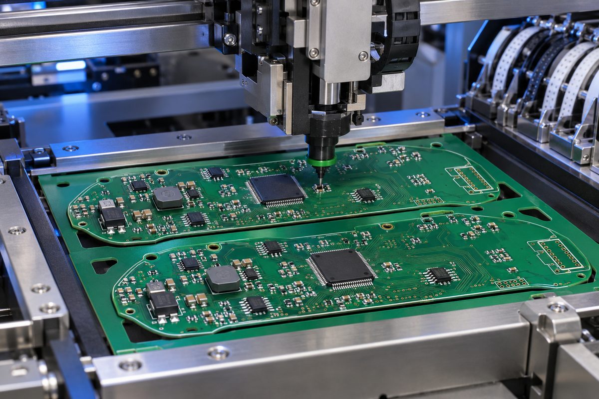
Assembly planning connects those board features to the actual components. Fine-pitch devices need suitable paste deposits and placement control; display connectors need correct orientation and mechanical alignment. Boards containing hidden terminations require an inspection approach suited to those packages.
Our automotive PCB assembly service brings fabrication, component preparation, soldering, and agreed inspection requirements into one production workflow. Firmware loading and functional checks are defined around the released software, interfaces, and test setup for the project.
How Is an Instrument Cluster Control Module Tested?
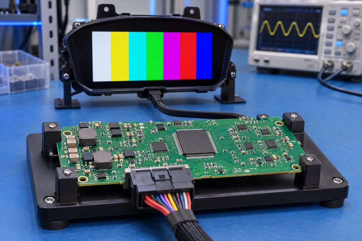
An instrument cluster control module is tested at several levels because assembly quality and operating behavior are different questions. Visual inspection can identify placement problems, while powered testing determines whether the module performs its specified functions.
At the assembly stage, solder paste inspection examines deposits before placement. AOI evaluates visible component and solder features. X-ray inspection can examine selected hidden-joint features beneath packages such as BGAs, but an acceptable image alone does not prove electrical function.
A board-level functional sequence typically covers the following areas, with limits set by the product specification.
- Power-up and supply behavior. Measure input current, regulated rails, reset behavior, and the transition into normal operation.
- Programming and startup. Verify the intended firmware revision, successful boot, and any required configuration data.
- Vehicle inputs. Apply known messages or sensor signals and compare the displayed values with the expected results.
- Display and warning outputs. Exercise image patterns, brightness control, telltales, and audible warnings where fitted.
- Fault and power-state behavior. Check defined responses to lost messages, invalid inputs, sleep commands, and wake-up events.
Accessible circuit board test points help connect the fixture to power rails, programming interfaces, and diagnostic signals without repeated manual probing.
Screen-level checks require the intended display or a suitable representative setup. Vehicle integration and environmental qualification extend beyond a routine PCBA production test. Temperature, vibration, electrical disturbances, and electromagnetic compatibility are evaluated against the requirements of the finished product.
Digital Instrument Cluster Interface PCB Case Study
Application
For a dashboard ECU bridge project, EBest Circuit’s PCB manufacturing work focused on a four-layer interface board for vehicle instrument electronics. The project involved a small prototype build, with board thickness, copper construction, and impedance requirements defined for the customer’s design.
| Project item | Requirement |
|---|---|
| Board construction | Four-layer FR4, Tg 130°C |
| Finished thickness | 1.53 mm ±10% |
| Outer-layer copper | 0.5 oz base copper, plated to meet a 40 µm finished-copper requirement |
| Inner-layer copper | 1 oz |
| Minimum hole-wall copper | 25 µm |
| Surface finish | Lead-free HASL |
| Signal routing | Controlled impedance according to the design requirements |
| Prototype quantity | 3 boards plus 1 spare, supplied as individual boards |
Challenge
The fabrication challenge was to satisfy the board’s mechanical and electrical requirements together. Impedance depends on trace geometry, copper thickness, and the dielectric structure, so the 1.53 mm finished thickness and outer-layer plating requirement could not be treated as unrelated specifications. The plated holes also needed at least 25 µm of wall copper while remaining compatible with the finished-hole requirements.
Solution
We used a four-layer FR4 construction with 1 oz inner copper and 0.5 oz outer base copper followed by plating to the specified finished thickness. The fabrication requirements combined impedance control with the board-thickness tolerance and minimum hole-wall copper, rather than applying a generic four-layer stackup. Lead-free HASL and individual-board delivery completed the specified build configuration for subsequent assembly.
Customer Benefit
The small prototype quantity limited the customer’s initial hardware commitment while providing boards for assembly and interface evaluation, including a spare. Coordinating the stackup, copper, and plated-hole requirements supported the intended electrical and mechanical fit of the dashboard interface board. It also established a defined fabrication configuration for subsequent revisions.
Why Choose EBest Circuit for Digital Cluster PCB Assembly?
Digital cluster boards combine display connections, vehicle interfaces, processing devices, and power circuits on a compact assembly. EBest Circuit brings experienced engineering support, our own PCB and PCBA factories, and traceable production together to manage the manufacturing details that affect these boards.
Certified Quality Systems with an Automotive Focus
We hold ISO 9001, ISO 13485, IATF 16949, and AS9100D certifications. For automotive instrument projects, IATF 16949 is particularly relevant to the manufacturing quality system. Our quality approach connects material identification, process control, engineering changes, and production records, helping customers manage repeat builds and investigate issues against a documented manufacturing history.
DFM Reports and BOM Optimization from Experienced Engineers
Our technical team includes R&D and PCB/PCBA engineers with 20 years of experience. We provide DFM pre-review reports, BOM optimization lists, and process-matching recommendations. For a cluster board, that means addressing processor fan-out, impedance-related stackup requirements, display-connector footprints, soldering access, and test-point placement before production. Proposed component changes are reviewed for electrical, package, and firmware compatibility before customer approval.
Our Own PCB and PCBA Factories with Integrated Sourcing
We integrate PCB fabrication, component procurement, assembly, and testing, supported by more than 1,000 supply-chain partners. This connects bare-board features with downstream assembly needs, from connector-hole dimensions to BGA pad structures. Procurement and production planning can be coordinated around the same BOM, reducing separate handoffs between board suppliers, component buyers, and assemblers.
Prototype and Small-Batch Support for Instrument Development
We support samples and small batches so engineers can evaluate display connections, communication interfaces, and power behavior before increasing production volume. Eligible PCBA projects can be delivered in as little as 1.5 weeks once manufacturing files, components, and the required test setup are ready; the schedule depends on board complexity and the agreed scope.
Digital Traceability for Materials and Production Batches
Our digital workshop supports retrieval of material and product-batch information within five seconds, together with visibility into production progress and cycle information. For instrument projects moving through hardware revisions, this helps identify which material or product batch is involved when investigating an assembly issue or planning a follow-up build.
Digital Instrument Cluster FAQs
Is a TFT instrument cluster different from an LCD cluster?
TFT describes the thin-film transistor technology used to control pixels in many LCD panels. A TFT LCD is therefore a type of LCD, rather than a separate category opposed to LCD. Panel resolution, viewing angle, brightness, and interface still vary between products.
Can a new digital cluster simply replace an existing analog cluster?
Only when the hardware, firmware, wiring, and vehicle integration support that replacement. Connector fit alone is insufficient. Data protocols, configuration, mounting, and vehicle security or coding requirements can prevent an otherwise suitable display from operating as a direct replacement.
Does the instrument cluster have to share a processor with the infotainment screen?
No. The cluster can use its own controller or form part of a more integrated cockpit architecture. Sharing processing resources changes the software, startup, and fault-management requirements; it is not simply a way to remove one PCB.
Does an instrument PCB need conformal coating?
That depends on exposure to moisture and contamination, the enclosure, and the product’s environmental requirements. Coating is not a substitute for a suitable housing. Connector contacts, test interfaces, and other protected areas also need appropriate masking when coating is specified.
Does a PCBA quotation include the display, enclosure, and vehicle software?
Not automatically. The quotation should identify whether the delivery is an assembled circuit board, a board with a display, or a more complete module. Display integration, housing assembly, firmware provision, and vehicle-specific software are separate scope items unless included in the agreement.
What changes the cost of a digital instrument cluster PCB assembly?
Major contributors include the processor and memory, component availability, PCB construction, package complexity, production quantity, and test requirements. Display and optical components add further cost when they are included in the supply scope. A bare PCB price therefore cannot represent the cost of a complete instrument module.
EBest Circuit holds ISO 9001, ISO 13485, IATF 16949, and AS9100D certifications and provides integrated PCB manufacturing and assembly services for digital instrument cluster projects. With our own PCB and PCBA factories and more than 1,000 supply-chain partners, we coordinate fabrication, component sourcing, assembly, and testing through one team. Experienced engineers support your project from prototypes to production, while digital traceability links materials and product batches to production records. Email sales@bestpcbs.com, or visit Contact Us and complete the form at the bottom of the page to request a quotation and engineering review.