





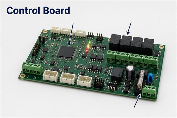
A control board is an electronic assembly that reads inputs, runs control logic and drives outputs for a machine or product. It may monitor switches, sensors and communication signals, then operate relays, valves, heaters, motors, displays or alarms.
The board is not defined by one standard circuit. Its architecture follows the end product: input voltage, load current, timing, safety function, environment, firmware and service strategy. That is why replacing a failed appliance board and developing a custom industrial controller are different engineering tasks.
Control Board Meaning
Control board meaning refers to the board’s system role, not merely its green PCB substrate. A printed circuit board becomes a control board when the assembled hardware and firmware form a decision-making and output-control unit.
Depending on the product, the same function may be called a controller board, main control board, electronic control board, control PCB or logic board. The name should not replace the part number, revision and product compatibility data needed for purchasing or repair.
How Does a Control Board Work?
A control board works in a repeating chain: condition the power, sample inputs, execute logic, command outputs and monitor the result. Simple boards may use comparators or timers; more flexible designs use an MCU with stored firmware.
- Power entry: a fuse, transient suppressor, reverse-polarity stage and regulators create stable rails.
- Input conditioning: filters, dividers, protection and isolation prepare sensor or switch signals.
- Processing: an MCU, processor or programmable logic device applies timing, limits and fault rules.
- Output drive: transistors, MOSFETs, triacs or relays switch the connected load.
- Feedback: current, position, temperature or communication data confirms whether the command succeeded.
In a safety-related function, the control strategy may also need watchdogs, redundant sensing, fail-safe states and independent hardware shutdown paths.
Control Board Components
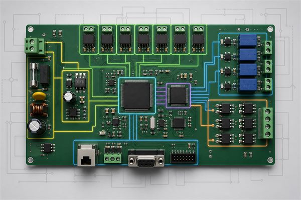
Control board components normally fall into six functional groups: power, processing, inputs, outputs, communication and protection. The exact selection depends on electrical stress, lifetime, availability and the end-use standard.
| Functional Block | Typical Components | Primary Job |
| Power | Fuse, TVS, rectifier, DC/DC, LDO | Create protected and regulated rails |
| Processing | MCU, oscillator, memory, watchdog | Run logic and store settings |
| Inputs | Filters, op-amps, ADC circuits, isolators | Read sensors and commands |
| Outputs | MOSFETs, drivers, triacs, relays | Switch loads and actuators |
| Communication | CAN, RS-485, UART, Ethernet transceivers | Exchange commands and diagnostics |
| Protection | ESD, surge, overcurrent and polarity protection | Limit predictable electrical faults |
What Is the Difference Between a Control Board and a PCB?
A PCB is the fabricated board that mechanically supports and electrically connects components; a control board is the complete functional assembly used to control a product. The terms overlap in casual use, but the distinction matters in manufacturing.
- A bare PCB purchase needs fabrication data, stackup, material, finish and mechanical requirements.
- A control-board assembly needs the PCB data plus BOM, placement data, assembly drawings, firmware handling and a test plan.
- A replacement control board also needs the exact compatible part number and revision.
This distinction prevents an RFQ for “one control board” from omitting the files needed to build and verify the product.
How Should a Control Board PCB Be Designed?
A control board PCB should be partitioned by power level, noise sensitivity and isolation requirement before detailed routing starts. Keep surge-prone power entry and switching nodes away from low-level analog sensing, clock circuits and communication references.
Useful layout decisions include:
- define high-current loops and return paths before placing connectors;
- put decoupling close to IC supply pins and keep switching loops compact;
- separate noisy relay, motor and triac areas from analog inputs;
- size traces, copper pours and vias for current and temperature rise;
- maintain application-appropriate clearance, creepage and isolation barriers;
- add accessible test points for power rails, reset, programming and critical I/O.
For related fabrication choices, review our PCB stackup and impedance-control guidelines and the role of DFM in PCB manufacturing.
Which Protection Circuits Matter Most?
The most important protection circuits are the ones tied to credible faults at the product interface. A 24 V industrial input, an automotive battery line and a low-voltage consumer board do not face the same transients.
- Power entry: overvoltage, undervoltage, reverse polarity, inrush and short-circuit protection.
- Inductive loads: flyback or clamp paths for relays, solenoids and motors.
- External ports: ESD and surge components with short, low-inductance return paths.
- Isolation: optocouplers, digital isolators or isolated power where field and logic domains must be separated.
- Thermal risk: temperature sensing, current limiting and a defined shutdown state.
Protection parts must be coordinated with connector ratings, copper geometry, enclosure grounding and the end product’s compliance plan. Adding a TVS diode without checking the complete current path is not a finished protection design.
How Is a Custom Control Board Manufactured?
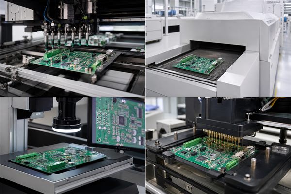
A custom control board is manufactured through data review, bare-board fabrication, component sourcing, SMT or through-hole assembly, inspection, programming and functional test. Each stage should use the same controlled revision.
- Review Gerber or ODB++ data, drill files, stackup, drawings, BOM and placement data.
- Resolve DFM and BOM questions before material release.
- Fabricate and electrically test the bare PCB.
- Assemble SMT and through-hole parts with controlled process parameters.
- Use inspection appropriate to the package mix, such as SPI, AOI or X-ray.
- Program firmware and execute functional tests with recorded acceptance criteria.
Our overview of the SMT process in PCB manufacturing explains the assembly sequence in more detail.
How Should Firmware and Test Coverage Be Planned?
Firmware and test coverage should be planned together because many failures are visible only when hardware, software and loads interact. A board that powers up is not necessarily controlling correctly.
A practical test strategy defines:
- rail voltage and current limits before programming;
- programming image, version, checksum and serialization method;
- input simulation for sensors, switches and communication ports;
- output loads or safe electronic substitutes for relays and drivers;
- fault-injection checks for open sensors, shorted outputs or supply limits;
- pass/fail thresholds and the data retained for traceability.
Design-for-test points and connector access should be decided before layout release, not after the first fixture is built.
Control Board Repair
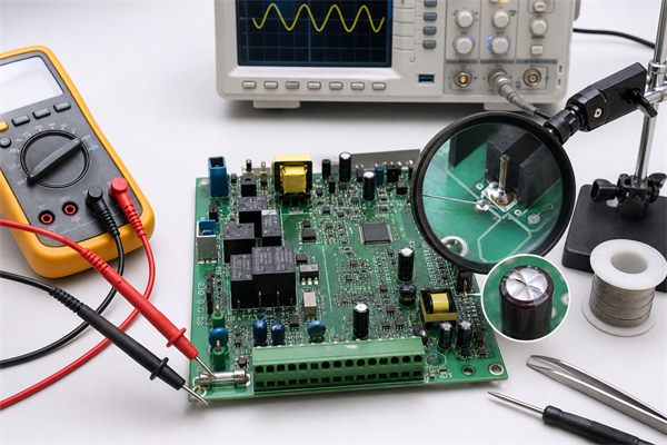
Control board repair starts with the power path and a verified symptom, not with random component replacement. Disconnect hazardous energy, discharge stored charge and follow the product’s service instructions before testing.
- Record the part number, revision, fault code and operating condition.
- Inspect for heat damage, contamination, cracked joints and damaged connectors.
- Check the fuse and protected input without bypassing the safety function.
- Verify regulator rails, reset and clock before investigating I/O.
- Test the suspected input and output with the correct load and isolation.
- After repair, repeat the product-level functional and safety checks.
Common failures include aged electrolytic capacitors, damaged surge parts, worn relay contacts, cracked solder joints and external loads that repeatedly overstress the board.
When Is Redesign Better Than Repair?
Redesign is better than repair when the failure is systemic, parts are obsolete, safety requirements changed or the original board cannot be tested consistently. A one-time cracked joint may justify repair; repeated field returns at the same hot relay or connector indicate a design or application problem.
| Situation | Better Path | Reason |
| Isolated workmanship defect | Repair and retest | Original design remains valid |
| Repeated overheating at one circuit | Root-cause redesign | Repair does not remove the stress |
| Obsolete critical component | Controlled redesign | Substitution may affect firmware or compliance |
| Missing source and test data | Re-document before volume build | Uncontrolled reproduction creates quality risk |
Before changing a legacy assembly, confirm interfaces, loads, timing, firmware ownership, mechanical fit and regulatory impact.
What Files Are Needed for a Control Board Quote?
A useful control board quotation needs enough controlled data to price both fabrication and assembly. At minimum, prepare:
- Gerber or ODB++ files, NC drill data and the PCB fabrication drawing;
- stackup, material, copper, thickness, finish and impedance requirements;
- BOM with manufacturer part numbers, approved alternatives and DNI items;
- centroid data, assembly drawings and polarity references;
- firmware/programming instructions and the required security handling;
- test specification, fixture ownership and acceptance limits;
- prototype and production quantities plus delivery destination.
A clear package shortens clarification time and keeps revisions aligned across PCB, PCBA and test.
FAQ About Control Boards
Is a control board the same as a motherboard?
No. A motherboard is a main computing platform, while a control board is optimized to monitor and operate a particular product or process.
Can a control board work without firmware?
Yes, some simple analog or logic-based boards can. MCU-based boards normally require firmware before functional testing.
Why do control boards use relays?
Relays provide galvanic separation and can switch AC or DC loads, but contact life, coil drive and inductive suppression must be considered.
What makes a control board fail?
Typical causes include power surges, overheating, moisture, contamination, vibration, connector damage, aged components and overstressed external loads.
Can a burned control board be repaired?
Sometimes. The repair is acceptable only if the root cause, damaged layers, safety impact and post-repair test coverage can be established.
How do you identify the correct replacement board?
Match the equipment model, board part number, hardware revision, firmware compatibility, connectors and required configuration.
Does conformal coating make a board waterproof?
No. Coating can improve environmental protection, but material, coverage, connector exposure and enclosure design determine the actual protection level.
What is the best PCB material for a control board?
FR-4 is common, but temperature, voltage, frequency, thermal load and certification needs determine the correct material and grade.
Should every control board have isolation?
No. Isolation is used where voltage domains, noise, ground potential or safety requirements justify it.
How is a control board tested in production?
Typical coverage combines bare-board electrical test, inspection, programming, in-circuit checks where appropriate and a product-specific functional test.
Can one control board be copied from a sample?
A sample can support analysis, but reliable reproduction also needs legal authorization, controlled design data, component identification, firmware and test criteria.
What quantity is suitable for a prototype build?
The quantity should cover engineering validation, destructive tests, fixture development and spares; it depends on the product’s verification plan.
How Can EBest Circuit Support Your Control Board Project?
At EBest Circuit, we support custom PCB fabrication and assembly from engineering prototypes through repeat production. We can review your data package, identify DFM and BOM questions, assemble the board and work with your defined programming and functional-test requirements.
Send your Gerber files, BOM, quantity, assembly drawings and test requirements to sales@bestpcbs.com. We will review the package and confirm the manufacturing path for your control board.







