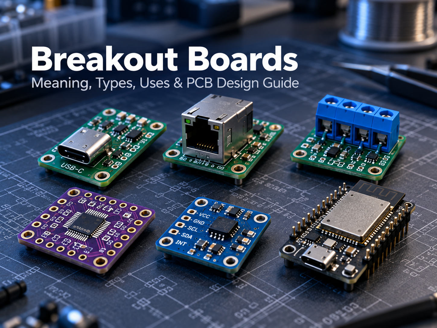
A breakout board is a small PCB that takes difficult-to-access pins from an IC, sensor, module, or connector and routes them to larger pads, headers, or terminals. This makes fine-pitch or compact components much easier to prototype, test, and connect without designing a complete custom PCB first.
Breakout boards are widely used with Arduino, ESP32, sensors, USB-C, RJ45, SMD packages, and power connectors. Some simply expose pins, while others add regulators, pull-up resistors, level shifting, ESD protection, or signal conditioning. Understanding that difference matters when selecting or designing a board.
What Is a Breakout Board?
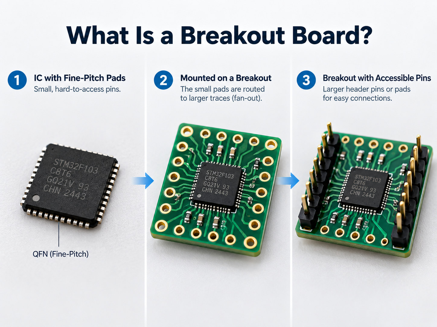
A breakout board is a small printed circuit board that converts a difficult component interface into a connection that is easier to access. For example, a QFN sensor may have pads spaced too closely for jumper wires or a breadboard, so the breakout PCB routes those pads outward.
Common connection formats include:
- 2.54 mm pin headers
- Screw terminals
- Test pads
- Edge connectors
- Larger solder pads
The same principle applies to connectors. A USB-C or RJ45 breakout board exposes individual connector contacts so they can be reached during prototyping, testing, or wiring.
Breakout boards usually perform one focused task. They are not necessarily complete development platforms and may contain no processor, firmware, or programmable circuitry.
How Does a Breakout Board Work?
A breakout board routes closely spaced component or connector pins through PCB copper traces to larger, easier-to-use connection points. The basic signal path is:
Component or connector → PCB fan-out traces → accessible pads or headers
A typical breakout board may contain:
- The main IC, sensor, module, or connector
- Copper fan-out routing
- Pin headers or terminal blocks
- Ground and power connections
- Decoupling capacitors
- Optional supporting components
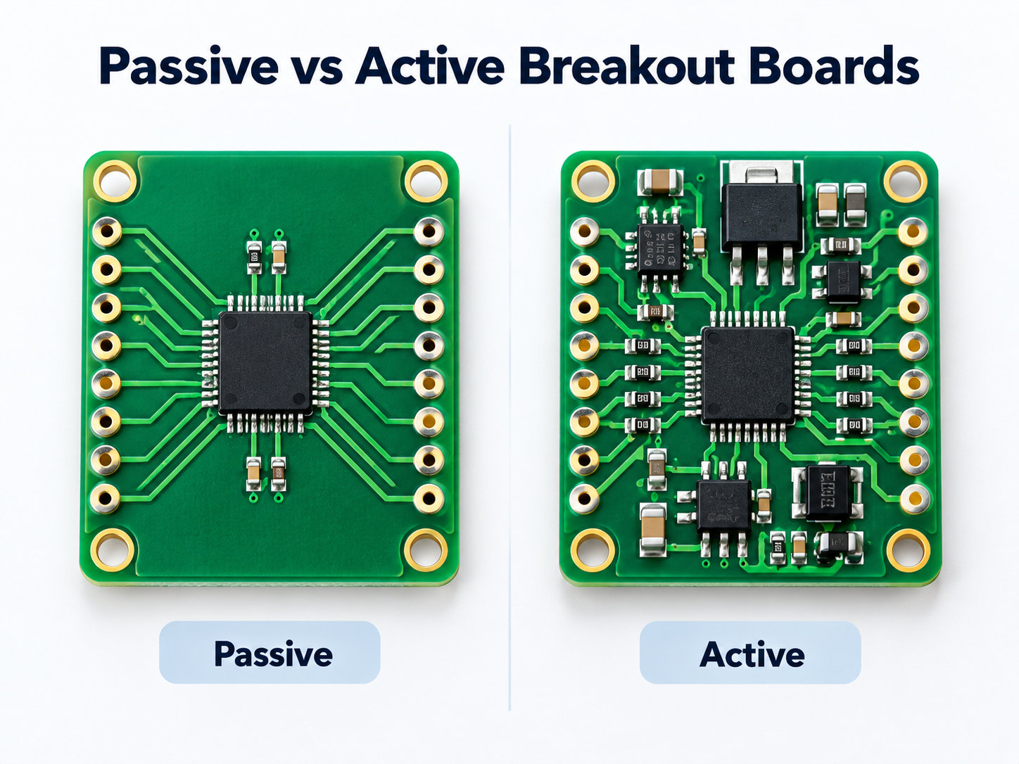
On a passive board, the traces may connect almost directly from the device pins to the headers. An active breakout can add functions such as voltage regulation or level shifting, allowing a low-voltage sensor to interface safely with a 3.3 V or 5 V controller.
The PCB can also simplify pin identification. Silkscreen labels such as VCC, GND, SDA, SCL, TX, RX, D+ and D- help reduce wiring errors during prototyping.
What Are the Main Types of Breakout Boards?
Breakout boards are usually classified by the component or interface they make easier to access.
| Breakout Board Type | What It Exposes | Common Examples |
|---|---|---|
| SMD / IC breakout | Fine-pitch package pins | QFN, DFN, SOIC, TSSOP |
| Sensor breakout | Sensor power and I/O | IMU, pressure, temperature |
| MCU / module breakout | GPIO and communication pins | ESP32 modules |
| Connector breakout | Connector contacts | USB-C, USB, RJ45 |
| Power breakout | Power supply rails | ATX connectors |
| Communication breakout | Bus or transceiver signals | CAN, RS485, UART |
SMD breakout boards help when a surface-mount package cannot plug directly into a breadboard, while sensor breakout boards may add decoupling, pull-ups, or voltage support around the sensor.
Connector breakout boards expose contacts through headers, pads, or screw terminals. Power breakout boards separate supply rails into accessible connection points for prototyping or test setups.
At EBest Circuit, custom breakout board projects can be reviewed together with the component footprint, connector layout, BOM, assembly process, and test requirements before prototype fabrication.
Passive vs Active Breakout Boards: What Is the Difference?
A passive breakout board mainly reroutes electrical connections, while an active breakout board adds circuitry that changes, protects, or conditions the signal or power.
A passive breakout board may contain only:
- Copper traces
- Pads
- Headers
- Connectors
- Screw terminals
Typical examples include an RJ45-to-terminal adapter or a QFN-to-DIP adapter. An active breakout board may add:
- Voltage regulators
- Pull-up or pull-down resistors
- Logic-level shifters
- ESD protection
- Filters
- Transceivers
- Oscillators
- Signal-conditioning ICs
Two boards using the same connector can therefore behave very differently. A passive USB-C breakout may only expose connector pins, while another design may include CC resistors, a power controller, or a USB interface IC.
Before connecting a breakout board, check its schematic or pinout rather than assuming every pin is routed directly from the original device.
How Are Breakout Boards Used with Arduino and ESP32?
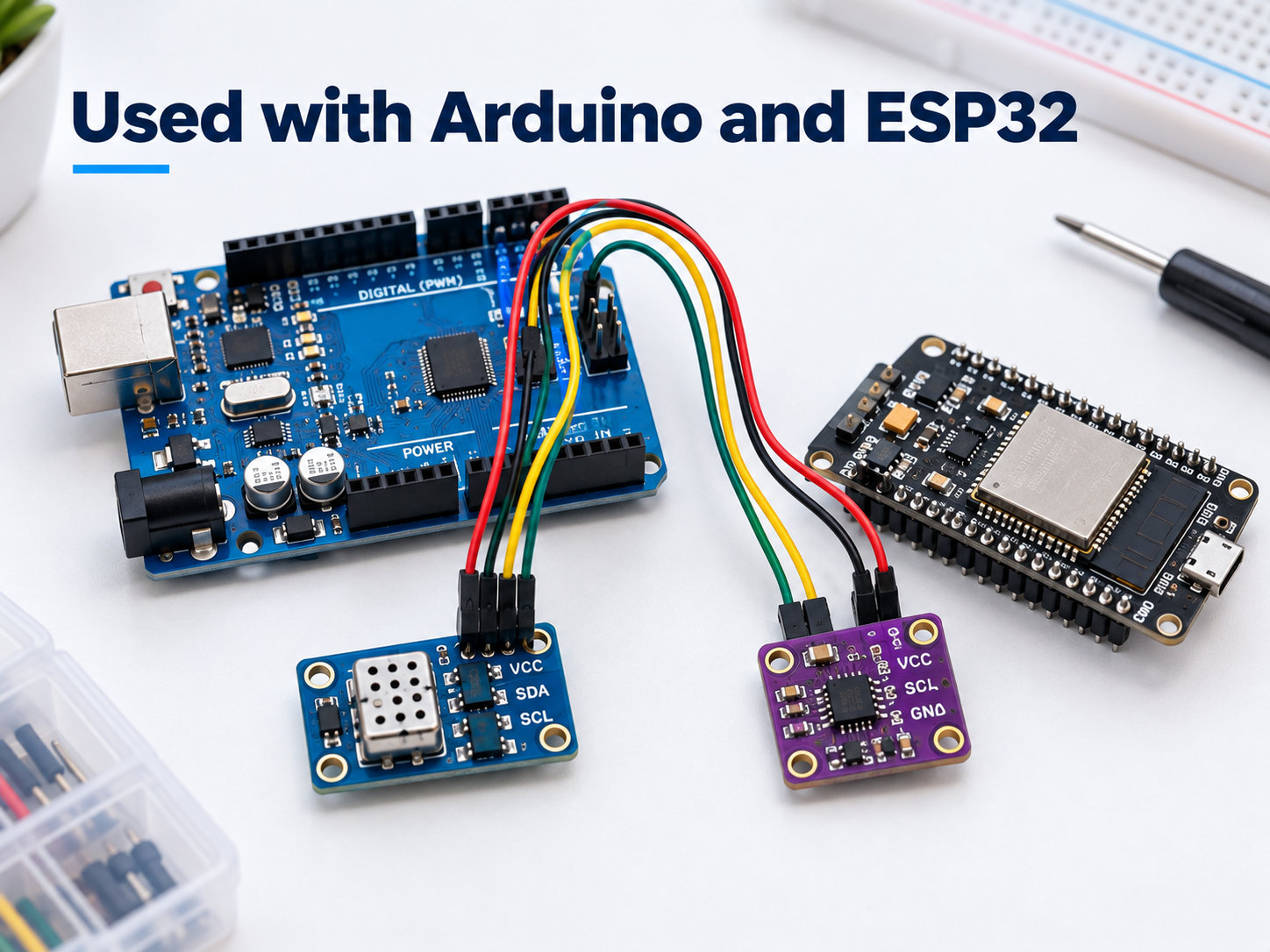
Breakout boards make it easier to connect sensors, interfaces, and modules to Arduino or ESP32 development boards without creating a custom PCB first.
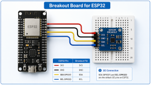
A breakout board for ESP32 can fan out compact module pins to standard headers, labeled GPIO connections, or terminal blocks for faster bench testing.
Common connections include:
- GPIO
- I²C
- SPI
- UART
- PWM
- Analog signals
- Power and ground
A sensor breakout may expose VCC, GND, SDA, and SCL, allowing it to connect directly to an Arduino or ESP32 through I²C. An ESP32 breakout board may instead route the module’s closely spaced pins to standard headers, terminal blocks, or clearly labeled GPIO connections.
Voltage compatibility still needs to be checked because ESP32 GPIO typically operates at 3.3 V, while some Arduino boards use 5 V logic. Also confirm whether the breakout already includes pull-ups, voltage regulation, USB-to-UART circuitry, EN or BOOT controls, or level shifting.
What Should You Check on USB-C, RJ45 and Screw-Terminal Breakout Boards?
Connector breakout boards should be selected by electrical capability, not just connector shape.
For USB-C breakout boards, check:
- Which of the 24 USB-C pins are exposed
- Whether CC1 and CC2 are available
- Whether CC resistors are installed
- USB 2.0 or higher-speed data support
- Differential-pair routing
- Current rating
- Whether USB Power Delivery circuitry is included
A USB-C receptacle does not automatically mean the board supports Power Delivery or high-speed USB. For RJ45 breakout boards, check whether the board simply exposes all eight contacts or also includes magnetics, LEDs, shielding, or Ethernet-specific circuitry.
For screw-terminal breakout boards, check:
- Terminal pitch
- Wire gauge
- Current rating
- Voltage rating
- Connector pin mapping
Breakout Board vs Breadboard vs Development Board: What Is the Difference?
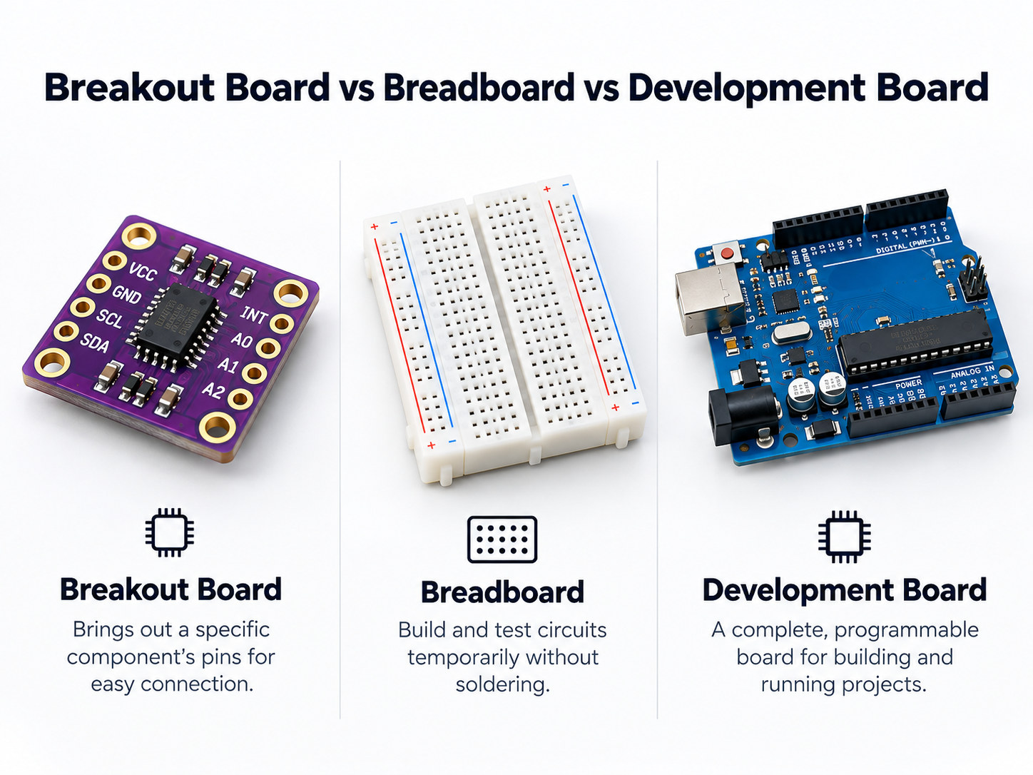
A breakout board, breadboard, and development board all support prototyping, but they solve different problems.
| Feature | Breakout Board | Breadboard | Development Board |
|---|---|---|---|
| Main purpose | Expose component pins | Build temporary circuits | Run and program a controller |
| Is it a PCB? | Yes | Usually no | Yes |
| Usually programmable? | No | No | Yes |
| Contains target IC? | Often | Not by itself | Yes |
| Typical use | Component evaluation | Wiring experiments | Firmware and system development |
A breadboard provides reusable connection points for temporary circuits, while a breakout board adapts a specific component or connector into a more convenient electrical interface.
A development board normally contains a programmable MCU or processor plus support circuitry such as USB, clocks, memory, voltage regulation, and programming interfaces. Arduino and ESP32 development boards fit this category; a separate sensor or connector PCB attached to them is usually the breakout board.
What Matters When Designing a Custom Breakout Board PCB?
A custom breakout board should make the target component easier to use without creating new electrical, mechanical, or assembly problems.
A breakout board PCB design should preserve the component pinout while making power, signals, mounting, and test access easier to verify.
Important PCB design checks include:
- Correct component footprint
- Header or terminal pitch
- Pin numbering and silkscreen labels
- Fan-out routing from fine-pitch packages
- Power and ground routing
- Decoupling capacitor placement
- Ground-plane continuity
- Test points
- Mounting holes
- Connector mechanical support
Active breakout boards may also need voltage regulation, level shifting, ESD protection, filtering, pull-up resistors, or signal conditioning.
High-speed interfaces need tighter PCB control. USB, Ethernet-related signals, RF modules, and fast differential buses may require controlled impedance, matched differential pairs, short stubs, and continuous return paths.
Very small QFN, DFN, or BGA packages can also affect manufacturability. They may require tighter solder-mask alignment, via-in-pad structures, or X-ray inspection after assembly.
EBest Circuit can review breakout-board Gerber files, BOMs, connector footprints, stackups, fine-pitch packages, and PCBA requirements during DFM before prototype fabrication.

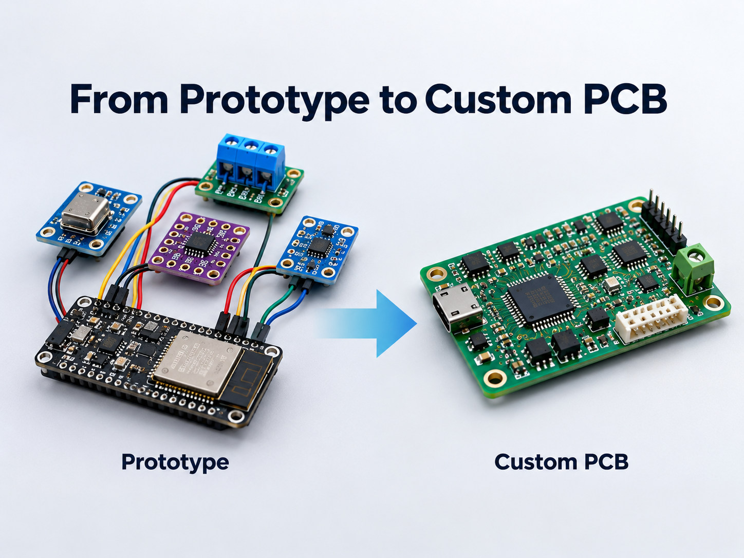
When Should You Replace a Breakout Board with a Custom PCB?
A breakout board is useful during evaluation, but a custom PCB usually becomes more practical once the circuit architecture is stable.
Consider moving to a custom PCB when:
- The prototype has been electrically validated.
- Several breakout boards are connected together.
- Product size must be reduced.
- Connectors need fixed mechanical positioning.
- Production quantity is increasing.
- Assembly time is becoming expensive.
- Signal integrity or EMC performance matters.
- Power distribution needs tighter control.
- BOM cost needs to be reduced.
- Repeated manual wiring is creating errors.
A custom PCB can combine the validated functions into one layout with fixed connector positions, shorter interconnects, defined mounting, and repeatable assembly.
FAQ About Breakout Boards
1. Is a breakout board the same as a PCB?
A breakout board is a type of PCB. It is usually designed around one component, module, connector, or interface rather than a complete product circuit.
2. What does breakout board mean?
It means a board that “breaks out” difficult-to-access electrical pins into larger, easier connection points such as headers, pads, or terminals.
3. Is an SMD adapter a breakout board?
Yes. Many SMD adapters are breakout boards because they convert fine-pitch SMD pins into breadboard-friendly or through-hole connections.
4. Can one breakout board work with both Arduino and ESP32?
Sometimes. The pin interface may be compatible, but voltage levels, power requirements, and communication settings must also match.
5. Can breakout boards be used in production products?
Yes, but they are more commonly used for prototyping, testing, and low-volume systems. A custom PCB is usually more compact and economical for larger production runs.
6. Do USB-C breakout boards support Power Delivery?
Not necessarily. A basic USB-C breakout may only expose connector pins. USB Power Delivery requires the appropriate CC and PD controller circuitry.
Ready to Turn a Breakout Board Prototype into a Custom PCB?
Breakout boards are effective for proving a circuit quickly, but production hardware usually needs a more integrated layout with controlled power, fixed connectors, shorter interconnects, and repeatable assembly.
EBest Circuit supports custom PCB fabrication, fine-pitch component assembly, connector assembly, DFM review, and prototype-to-production PCBA. If your prototype is moving beyond breakout boards, send your Gerber files, BOM, schematics, and assembly requirements to sales@bestpcbs.com for engineering review.