





Understanding the types of USB ports requires separating the connector shape from the data, power and video standards behind it. USB-A, USB-B, Mini-USB, Micro-USB and USB-C describe physical interfaces; USB 2.0, USB 3.2 and USB4 describe performance families. These USB port types are not interchangeable labels, and a familiar connector shape alone does not confirm speed, charging power or display support.
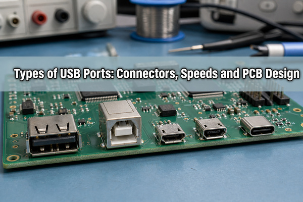
What Are the Different Types of USB Ports?
The main USB connector families are Standard-A, Standard-B, Mini-B, Micro-B and Type-C. Micro-AB and legacy Mini-A variants also exist, but they are less common in current product designs. The practical choice depends on the product role, enclosure space, mating cycle requirement, required data lanes and whether reversible insertion is needed.
- USB-A: commonly used on host equipment, chargers, desktop computers and industrial control panels.
- USB-B: a robust device-side connector associated with printers, instruments and larger peripherals.
- Mini-USB: a legacy compact family found on older cameras, controllers and embedded equipment.
- Micro-USB: a smaller legacy device connector still used in cost-sensitive or established products.
- USB-C: a reversible connector that can be implemented for USB 2.0, USB 3.2, USB4, USB Power Delivery and selected alternate modes, depending on the complete hardware design.
The connector at each end of a cable must be identified separately. An A-to-C cable, for example, has a USB-A plug at one end and a USB-C plug at the other; that description still does not reveal its supported data rate or charging capability.
How Do USB-A, USB-B, Mini-USB, Micro-USB and USB-C Differ?
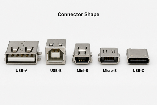
Connector selection begins with product role and mechanical constraints. The table compares physical characteristics rather than promising a particular protocol or power level.
| Connector | Typical Role | Insertion | Design Considerations |
|---|---|---|---|
| USB-A | Host or power-source port | One orientation | Large footprint; strong shell anchoring; many legacy products |
| USB-B | Device-side port | One orientation | Mechanically robust but tall; suitable for instruments and printers |
| Mini-B | Legacy portable device | One orientation | Obsolete for many new designs; replacement availability should be checked |
| Micro-B | Compact legacy device | One orientation | Low profile; plug alignment and shell fatigue require attention |
| USB-C | Host, device or dual-role | Reversible | More contacts and control requirements; capability depends on implementation |
For a new product, USB-C is often attractive when reversible insertion, compact packaging or scalable power is valuable. USB-A or USB-B can still be the better choice when compatibility with installed equipment, field-service simplicity or connector robustness matters more than size.
How Are USB Port Types Different from USB Versions?
A connector type defines mechanical mating and contact arrangement. A USB version or performance designation defines signaling capability. USB-IF explicitly states that USB Type-C is not the same as USB 3.2, USB4 or USB Power Delivery. A USB-C receptacle can be wired for USB 2.0 only, while a USB-A receptacle can support USB 5Gbps or USB 10Gbps when the host, device and cable all support that rate.
This distinction affects schematic design and BOM selection. A USB 2.0 Type-C device may use D+ and D- plus configuration-channel components without implementing SuperSpeed TX/RX pairs. A USB4 design needs the relevant high-speed controller or retimer architecture, full-featured Type-C routing, a qualified connector and cable, signal-integrity validation and firmware support.
The link operates at the best mutually supported capability of the host, device and cable. A high-performance host does not make a USB 2.0 peripheral faster, and a charge-only cable cannot provide a data connection.
What Speeds Can USB 2.0, USB 3.2 and USB4 Deliver?
Use advertised signaling capability rather than connector color or shape as the deciding specification. Actual application throughput is lower than the signaling rate because protocol overhead, device architecture, storage speed, cable loss and software all affect the result.
| Performance Family | Maximum Signaling Rate | PCB Impact |
|---|---|---|
| USB 2.0 High-Speed | 480 Mbps | One D+/D- differential pair; controlled routing and ESD protection |
| USB 5Gbps | 5 Gbps | SuperSpeed TX/RX pairs, tighter loss and discontinuity control |
| USB 10Gbps | 10 Gbps | More demanding stackup, connector launch and channel validation |
| USB 20Gbps | 20 Gbps | Two-lane Type-C implementation and full-channel budget control |
| USB4 | 20, 40 or 80 Gbps by implementation | Type-C architecture, lane management and rigorous signal-integrity design |
For product documentation, specify the supported rate directly, such as USB 10Gbps, instead of relying only on historical names such as “USB 3.0.” This gives procurement, test and end users a measurable requirement.
What Power Can USB Ports Deliver?
Power capability depends on the port role, advertised current, cable rating and negotiated protocol. A conventional USB 2.0 configured device may draw up to 500 mA at 5 V, while a USB 3.x configured device may draw up to 900 mA at 5 V. Dedicated charging schemes and Type-C current advertisement introduce other permitted levels.
USB Power Delivery is a separate protocol and hardware solution. A compliant USB-C system can negotiate higher voltage and current, with Extended Power Range implementations reaching up to 240 W when the source, sink, cable and protection design all support that level. The presence of a USB-C connector alone does not guarantee USB PD.
PCB designers should size VBUS copper for the negotiated current, protect against short circuit and overvoltage, control connector temperature rise, and select a connector and cable for the intended current. Higher-power Type-C designs also need correct CC logic, cable capability detection and thermal validation at the receptacle and power switches.
How Can You Identify a USB Port by Shape, Symbol and Color?
Shape is the most reliable first check: USB-A is flat and rectangular, USB-B is approximately square with beveled upper corners, Micro-B is thin and keyed, and USB-C is a small rounded rectangle with a centered tongue and reversible mating.
Symbols and certified performance markings provide better evidence than plastic color. Blue inserts are often associated with 5Gbps USB-A ports, but color is a manufacturer convention rather than a complete technical guarantee. Black, white, red, teal or yellow inserts can reflect product styling, charging behavior or vendor-specific choices.
Confirm the port using the equipment manual, PCB schematic, controller part number, connector pinout and tested enumeration speed. A SuperSpeed USB-A receptacle normally has additional contacts behind the four USB 2.0 contacts. For Type-C, verify whether the product supports USB 2.0, USB 5/10/20/40/80Gbps, USB PD and alternate modes separately.
Which USB Port Type Should You Choose for a Product?
Choose the minimum implementation that meets the real system requirement, then validate connector availability and mechanical life. Adding USB-C or higher data rates without a system need increases controller, routing, compliance and test complexity.
| Product Requirement | Practical Starting Point | Key Check |
|---|---|---|
| Low-cost service or configuration port | USB 2.0 Micro-B or USB 2.0 Type-C | Field cable availability and connector retention |
| Legacy host compatibility | USB-A host port | Required current, orientation and enclosure access |
| Industrial instrument or printer-style device | USB-B device port | Panel thickness, shell grounding and vibration |
| Compact reversible consumer or portable product | USB-C | Exact data, charging and alternate-mode capability |
| High-speed storage, dock or display path | USB-C with defined 10/20/40/80Gbps capability | Controller, cable, channel loss and compliance plan |
A rigid-flex PCB can reduce internal cable and connector count in folding, camera or compact assemblies, but the high-speed transition must still be modeled across rigid and flexible sections. Conventional products can use an appropriately designed FR4 PCB with a stackup selected for the required differential impedance and loss budget.
What PCB Layout Rules Matter for USB Ports?
Start with the controller vendor’s layout guide and the selected PCB stackup. For USB 2.0, D+ and D- are commonly routed as a nominal 90-ohm differential pair over a continuous reference plane. Keep the pair short, control spacing and width, minimize skew, avoid plane gaps, and avoid long test-point stubs. Faster USB channels require a complete loss and discontinuity budget rather than a single generic trace rule.
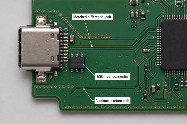
- Place the ESD protection device close to the receptacle so the surge path is short and direct.
- Maintain a continuous return path under every high-speed pair and add nearby ground transitions when changing layers.
- Reduce unnecessary vias, stubs, sharp discontinuities and reference-plane changes.
- Keep switching regulators, clocks, crystals and noisy power nodes away from USB data pairs.
- Review the connector launch, pad geometry, anti-pad and shell-ground strategy as part of the channel.
- Route VBUS for current and temperature rise, not only for electrical connectivity.
The connector manufacturer’s recommended footprint is the starting point, not an automatic approval. Check stencil apertures, solder-mask clearance, board-edge location, mating access and whether the shell tabs are through-hole, SMT or hybrid anchors.
How Should USB Connectors Be Mounted and Tested?
USB connector failures are often mechanical before they are electrical. Align the mating axis with the enclosure opening, support insertion and extraction loads through shell stakes or mounting tabs, and prevent the cable from levering only on signal pads. For edge-mounted Type-C connectors, verify PCB thickness, cutout dimensions, coplanarity and solder access.
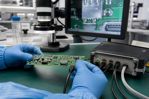
During PCB assembly, inspection should cover pin wetting, bridges, insufficient solder, shell-anchor fill, connector tilt and contamination. AOI can inspect visible joints; X-ray is useful when shell geometry or hidden pads obscure critical connections. Functional testing should confirm enumeration, negotiated speed, VBUS behavior, CC orientation for Type-C, data transfer under load and repeated plug reversal where applicable.
For integrated builds, EBest Circuit (Best Technology) lists USB/DC cable capability within its wire-harness services and provides PCB design/layout, fabrication, component sourcing, assembly and functional testing. Its published capability data states that the fastest PCBA turnaround can reach one day, subject to BOM readiness, board complexity and engineering review.
A useful manufacturing package includes the connector manufacturer and part number, rated mating cycles, board stackup, controlled-impedance requirements, enclosure drawing, cable orientation, USB protocol and speed, maximum power, ESD target, inspection criteria and functional-test method. The related USB port pin configuration guide can help verify pin assignments before layout release.
FAQ About Types of USB Ports
What Does USB Stand For?
USB stands for Universal Serial Bus. It defines a standardized way for hosts, devices, hubs and cables to exchange data and, where supported, deliver power.
What Is USB-A and B and C?
USB-A, USB-B and USB-C are connector families. USB-A is commonly host-side, USB-B is traditionally device-side, and USB-C is reversible and can support host, device or dual-role operation. Their shape does not by itself specify data speed or charging power.
What Are the Four Types of USB Cords?
Retail guides often group cords by USB-A, USB-B, Micro-USB and USB-C, but that is not a complete technical classification. Mini-USB and multiple plug combinations also exist. Specify both cable ends, supported data rate and power rating.
How to tell if A USB port is 2 or 3?
Check the manual, performance logo, controller specification or measured link speed. A blue USB-A insert and extra internal contacts often indicate a USB 3.x-capable port, but color alone is not proof.
What Does USB-C Look Like?
A USB-C receptacle has a small rounded-rectangle opening and a centered contact tongue. The plug can be inserted in either orientation.
Can a USB-C Port Support USB 2.0 Only?
Yes. USB-IF documents USB 2.0 Type-C implementations that carry USB 2.0 data without USB 3.2, USB4 or alternate-mode signal contacts. Power Delivery may still be supported if the product implements it.
Conclusion
The practical way to compare the types of USB ports is to identify four separate items: connector shape, supported data rate, power capability and optional video or alternate modes. For PCB development, also verify the controller, footprint, stackup, differential routing, ESD path, mechanical anchors and production test plan.
For a USB interface PCB or PCBA review, send the schematic, Gerber or ODB++ data, stackup, BOM, connector drawing, enclosure constraints, required USB speed, power profile and test criteria to EBest Circuit (Best Technology) at sales@bestpcbs.com.
You may also like








Tags: types of usb ports, USB 3.2, USB PCB design, usb port types, USB-A, USB-B, USB-C, USB4