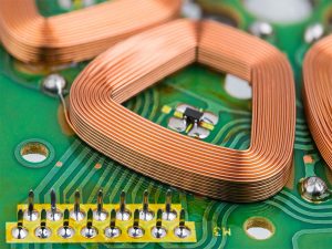
A pcb motor is an electric motor whose stator windings are formed as copper traces on a printed circuit board. In the common axial-flux arrangement, a thin PCB stator sits between one or two permanent-magnet rotors, producing a compact, coreless motor with repeatable winding geometry. The idea is attractive, but a successful design depends on electromagnetic, thermal, mechanical, and PCB manufacturing decisions being solved together.
The term is often confused with a motor control PCB. A controller board switches power into a separate motor. A PCB stator motor uses the circuit board itself as part of the electromechanical energy-conversion structure. Some products contain both, but they are not the same component.
What Is a PCB Motor?
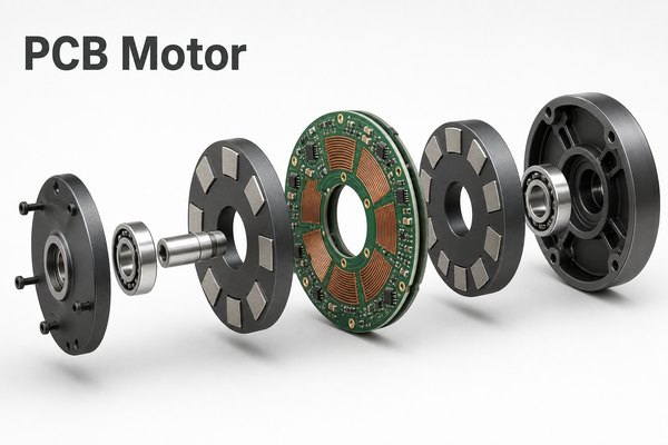
A PCB motor usually means a permanent-magnet motor that replaces wound copper coils with patterned conductors on a printed circuit board. The PCB becomes the stationary winding assembly, while permanent magnets rotate on one or both sides of it. Many practical versions are coreless, axial-flux, synchronous brushless machines.
This definition excludes a board that merely drives an external motor. A motor driver board contains switches, gate drivers, sensing, and protection. The PCB motor stator contains the phase conductors that create torque. Keeping those roles separate prevents the wrong thermal, current, and manufacturing assumptions from entering the design.
| Term | What the PCB Does | Main Design Concern |
| PCB motor | Forms the stator windings and may carry sensors or interconnects | Torque, copper loss, AC loss, temperature, air gap, and mechanics |
| Motor control PCB | Commutates and regulates a separate motor | Switching loops, power devices, sensing, EMI, and protection |
| Integrated motor assembly | Combines a PCB stator with control, sensing, or connectors | Electrical, thermal, magnetic, and mechanical co-design |
How Does an Axial Flux PCB Motor Work?
An axial flux pcb motor produces torque from the interaction between current in flat PCB windings and magnetic flux passing approximately parallel to the shaft. The rotor magnets face the stator disc. Electronic commutation energizes the phase windings in sequence, creating a rotating magnetic field that pulls the rotor around the axis.
- The drive electronics apply phase current to selected PCB coil sectors.
- The copper traces create a magnetic field across the rotor-stator air gap.
- The field interacts with the rotor magnets and produces tangential force.
- Rotor position feedback or a sensorless control method sets commutation timing.
- The process repeats as the rotor turns and mechanical power is delivered to the shaft.
Coreless construction removes stator teeth and their associated cogging mechanism, but it also removes the iron path that concentrates flux. The resulting motor is not automatically more efficient or more powerful. Magnet geometry, copper utilization, air-gap length, operating speed, cooling, and control strategy still decide the outcome.
What Does a PCB Motor Diagram Show?
A useful pcb motor diagram shows the complete magnetic and mechanical stack, not only the copper artwork. At minimum, it should identify the PCB stator, phase coil sectors, rotor discs, permanent magnets, shaft, bearings, and the air gaps on each side of the stator.
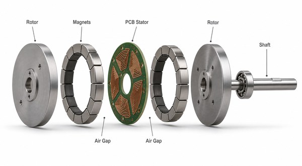
The diagram also reveals where disciplines meet. PCB thickness affects the magnetic gap. Bearing runout affects clearance. Magnet placement affects back EMF and torque ripple. Trace geometry affects resistance and induced voltage. A drawing that omits these interfaces may look complete while leaving the largest prototype risks unresolved.
Which PCB Motor Design Variables Control Torque and Loss?
PCB motor design is governed by coupled variables rather than one ideal coil shape. Increasing turns can raise induced voltage, but longer and narrower traces increase resistance. Adding copper layers can improve conductor utilization, but it also creates more layer transitions, registration dependencies, and AC-loss paths.
| Variable | Potential Benefit | Trade-off or Risk |
| More turns | Higher winding voltage constant | More resistance and less room for wide conductors |
| Wider or thicker copper | Lower DC resistance and lower temperature rise | Larger coil area, tighter spacing, and manufacturing limits |
| More PCB layers | More active copper within the same diameter | Via transitions, alignment, cost, and circulating-current risk |
| Smaller air gap | Stronger magnetic coupling | Greater sensitivity to warpage, runout, particles, and assembly tolerance |
| Higher speed | More power from a given torque level | Higher frequency-dependent copper loss, rotor stress, and bearing demands |
The correct sequence is to define torque, speed, voltage, envelope, duty cycle, cooling, and allowable temperature before optimizing the copper artwork. Starting with a visually appealing spiral and trying to infer performance afterward usually creates avoidable iteration.
How Should You Design the PCB Motor Stator?
The pcb motor stator should be designed as a balanced multiphysics structure. Its phase pattern must create the intended winding factor, carry current without excessive loss, remain manufacturable across every layer, and stay flat enough to preserve the mechanical air gap.
- Coil topology: select concentrated, distributed, spiral, wave, or another pattern from the pole-slot combination and target harmonic content.
- Phase symmetry: keep phase resistance, conductor length, and layer transitions as closely matched as the architecture permits.
- Copper utilization: maximize active conductor in the magnet sweep while maintaining fabrication clearances and insulation.
- Via strategy: place layer transitions where they do not create current crowding, weak annular rings, or asymmetric loops.
- Mechanical datum: define the center bore, mounting holes, rotor clearance, and balancing features from one controlled reference system.
- Sensor integration: keep Hall sensors or position-sensing features clear of high-current return paths and predictable magnetic interference.
Electromagnetic simulation should be paired with circuit and thermal models. The calculated phase current is only useful if the real board can conduct it over the required duty cycle without violating material or assembly limits.
Which Materials and Stackup Choices Matter?
Materials and stackup determine copper capacity, insulation, stiffness, flatness, thermal behavior, and cost. Standard rigid laminate may work for a prototype, but the final selection must be based on operating temperature, mechanical loading, dielectric requirements, copper construction, and the selected fabrication process.
| Stackup Decision | Why It Matters | What to Confirm |
| Laminate system | Sets thermal, dielectric, moisture, and mechanical behavior | Glass transition, decomposition margin, thickness, and availability |
| Copper weight and layer count | Controls resistance, fill factor, and conductor distribution | Finished copper, etching capability, spacing, and registration |
| Core and prepreg thickness | Contributes directly to the rotor-stator magnetic gap | Finished thickness tolerance, resin flow, and warpage |
| Via and interconnect structure | Connects coil sections between layers | Current sharing, drill limits, copper plating, and inspection |
| Surface protection | Protects copper and defines assembly interfaces | Solder-mask clearance, finish compatibility, wear, and insulation |
For unusually high current, temperature, or layer count, send the proposed stackup and conductor geometry to the PCB fabricator before freezing the electromagnetic model. A capability assumption that changes later can invalidate resistance, air-gap, and thermal calculations at the same time.
What Thermal and Current Limits Constrain PCB Windings?
Heat is one of the hardest limits in a PCB stator because planar conductors often provide less copper fill than wound-wire windings, while the stator sits inside a narrow rotating assembly. DC resistance creates I²R loss, and high-speed operation adds frequency-dependent loss from the changing magnetic field and current distribution.
A practical thermal assessment should include:
- phase resistance at cold and operating temperature;
- continuous, intermittent, startup, stall, and fault current;
- airflow or conductive heat paths through the housing;
- local current crowding at corners, neck-downs, pads, and vias;
- magnet and bearing temperature limits;
- laminate and solder-mask temperature margin;
- AC loss caused by rotor-field harmonics and switching frequency.
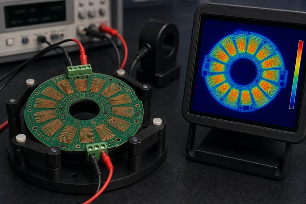
Do not set a current rating from trace width alone. The motor is an enclosed electromechanical system, so the allowable current must come from the verified winding temperature under the intended load profile and cooling condition. General high-power PCB design rules are useful, but they do not replace motor-specific thermal validation.
How Is a PCB Stator Manufactured and Assembled?
A PCB stator is manufactured with familiar multilayer PCB processes, but the circular geometry, large copper area, repeated coils, flatness requirement, and electromechanical tolerances make process coordination unusually important.
- DFM review: confirm layer count, finished copper, trace spacing, via structure, outline tolerance, slots, and mechanical datums.
- Imaging and etching: form repeatable coil patterns while controlling conductor width, spacing, and copper balance.
- Layer registration and lamination: align multilayer windings and control finished thickness and warpage.
- Drilling and plating: create layer transitions, terminals, and mounting features with verified copper continuity.
- Surface protection: apply solder mask and the selected surface finish to the intended assembly areas.
- Electrical inspection: verify continuity, isolation, resistance consistency, and shorts before motor assembly.
- Mechanical assembly: install bearings, shaft, rotors, and magnets while controlling concentricity and both air gaps.
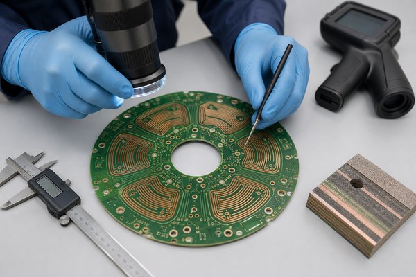
Panelization and depaneling also deserve attention. A circular stator needs sufficient support during fabrication without leaving tabs, burrs, or edge damage in magnet-clearance or mounting areas. The fabrication drawing should state which dimensions are mechanical datums rather than relying on the copper artwork alone.
How Do You Test a PCB Motor Prototype?
A prototype should be tested in stages so an electrical fault, magnetic mismatch, thermal problem, or mechanical interference can be isolated before a high-speed run. Open rotors and strong permanent magnets require guarding and controlled procedures.
- Bare-board checks: inspect the conductor pattern, dimensions, thickness, flatness, continuity, isolation, and phase resistance.
- Static assembly checks: confirm rotor clearance, bearing alignment, axial runout, magnet security, and shaft movement.
- Low-energy electrical checks: measure phase balance, inductance, sensor signals, and manually generated back EMF.
- Controlled no-load run: verify commutation order, direction, current, vibration, sound, and temperature rise behind a guard.
- Loaded characterization: record torque, speed, input power, winding temperature, and efficiency across the intended operating region.
- Abnormal-condition review: validate protection for stall, phase loss, sensor faults, overcurrent, and overtemperature as the product requires.
Test fixtures, drive firmware, sampling rate, and thermal soak time should be documented. A single successful spin proves rotation, not a reliable design.
When Does a PCB Motor Fit Better Than a Conventional Motor?
A PCB motor fits best when thin geometry, low cogging, consistent printed windings, and application-specific integration matter more than maximum copper fill or an off-the-shelf supply chain. Conventional wound motors remain preferable when proven commodity availability, very high copper utilization, or established high-power platforms dominate the decision.
| Decision Factor | PCB Stator Motor | Conventional Wound Motor |
| Form factor | Strong fit for thin axial packages | Broad range, often cylindrical |
| Winding repeatability | Defined by artwork and PCB process | Depends on winding and assembly process |
| Cogging | Coreless designs can minimize it | Toothed designs require magnetic optimization |
| Copper fill | Limited by planar trace and stackup constraints | Often higher with three-dimensional windings |
| Customization | Geometry can be revised through design files | May require winding-tool or lamination changes |
| Risk focus | AC copper loss, thermal path, flatness, and air gap | Winding, insulation, lamination, and assembly variation |
Which Applications Suit PCB Motors?
PCB motors are candidates for applications that benefit from a flat package, smooth motion, controlled magnetic geometry, or tightly integrated electromechanics. Suitability still depends on torque-speed demand, duty cycle, cooling, environment, cost target, and production volume.
- compact fans, blowers, and pumps;
- robotic joints, haptic interfaces, and precision mechanisms;
- drones and lightweight motion systems when the complete power-to-weight result is favorable;
- laboratory instruments and optical mechanisms requiring smooth low-speed behavior;
- custom actuators in thin or unusual mechanical envelopes;
- generators or energy-conversion devices built around similar axial-flux geometry.
The application should be evaluated as a system. Replacing only the stator without reconsidering the rotor, bearings, cooling, drive electronics, and enclosure rarely captures the full benefit.
FAQs About PCB Motors
Is a PCB motor the same as a motor controller PCB?
No. A PCB motor uses printed conductors as the stator winding. A motor controller PCB switches and regulates power for a motor. One product may include both, but their electrical, thermal, and manufacturing functions are different.
Is every PCB motor an axial-flux motor?
No, but axial-flux geometry is common because a flat PCB stator naturally faces disc-shaped magnet rotors. Printed conductors can also support linear or other specialized motor structures.
Is a PCB motor brushless?
Most permanent-magnet PCB stator motors use electronic commutation and are brushless synchronous machines. The exact phase arrangement, sensor method, and control algorithm depend on the design.
Can a PCB motor use a standard FR-4 board?
A prototype may use a conventional rigid laminate, but the material must be checked against winding temperature, dielectric stress, thickness tolerance, flatness, mechanical load, and the motor environment. Material selection should follow verified requirements rather than a generic default.
Why can a PCB motor overheat?
Planar traces may have limited copper cross-section, and an enclosed stator may have a weak cooling path. DC resistance, current crowding, high-frequency magnetic fields, switching harmonics, and insufficient housing conduction can all add heat.
How many PCB layers should the stator use?
There is no universal layer count. More layers can add active copper, but they also add vias, alignment requirements, stackup thickness, AC-loss paths, and cost. Select the layer count from electromagnetic, thermal, mechanical, and fabrication models together.
What is the most critical mechanical tolerance?
The rotor-stator air gap is often the most sensitive system dimension. PCB thickness, warpage, bearing runout, rotor flatness, shaft alignment, magnet placement, and assembly datums all contribute to the real clearance.
Can a PCB motor produce high torque?
It can produce useful torque, but the result depends on motor diameter, magnet loading, air gap, current, cooling, winding geometry, and speed. The technology should not be selected from a headline torque claim without a complete operating-point analysis.
What files does a PCB fabricator need for a PCB stator?
Provide fabrication data for every copper and mask layer, the drill data, stackup, finished copper, finished thickness and tolerance, controlled dimensions, outline drawing, via requirements, test requirements, and notes that identify mechanical datums and critical air-gap-related features.
Should the PCB stator and motor controller be on one board?
Sometimes integration reduces wiring and size, but it can also expose sensitive control electronics to heat, magnetic fields, mechanical stress, and a difficult assembly sequence. Separate boards may simplify cooling, service, and iteration. Compare both architectures at system level.
How should a PCB motor prototype be validated?
Start with bare-board electrical and dimensional checks, then verify the stationary mechanical assembly. Continue with low-energy back-EMF and sensor checks, guarded no-load operation, and finally controlled torque-speed and thermal testing across the intended duty cycle.
Need Manufacturing Support for the PCB in a Motor Project?
A good PCB motor project closes with manufacturability, not simulation alone. Confirm the conductor geometry, stackup, via transitions, finished thickness, flatness, mechanical datums, inspection plan, and prototype test limits before release.
EBest Circuit supports PCB fabrication, component sourcing, and PCB assembly services for motor-related electronics. We do not replace your motor electromagnetic or mechanical design team, but our engineers can review the PCB manufacturing package against documented PCB manufacturing capabilities. When your pcb motor design files are ready, send the Gerber data, drill files, stackup, drawings, quantities, and test requirements for review and quotation.