PCB motor refers to a motor-related system where printed circuit boards play a critical role in enabling motion control, power delivery, and system integration in modern electronic devices. This article explains what a PCB motor is, how it works, the types used in today’s electronics, and how motor control PCBs, layout optimization, and system integration impact performance and reliability.
Do these PCB motor challenges sound familiar?
- It is difficult to clearly understand what a PCB motor means in real projects.
- Selecting the right motor control PCB or motor driver PCB often feels confusing.
- Poor PCB layout can lead to overheating, EMI, or unstable motor behavior.
- Integrating motor control with embedded systems creates signal and power challenges.
- Troubleshooting motor failures on a PCB takes time and often lacks clear direction.
A professional PCBA partner can turn these challenges into a structured engineering solution.
- Define the correct PCB motor architecture based on application needs.
- Select suitable motor control and driver solutions for stable operation.
- Optimize PCB layout to improve current flow, thermal performance, and EMI control.
- Design reliable interfaces between motor controllers and embedded systems.
- Apply systematic debugging methods to quickly locate and resolve faults.
EBest Circuit (Best Technology) is a professional PCB and PCBA manufacturer with strong experience in motor control PCB production, multilayer PCB fabrication, component sourcing, and assembly services. We support projects from engineering review to mass production with a focus on reliability and manufacturability. Pls feel free to contact us at sales@bestpcbs.com.
What Is a PCB Motor and How Does It Work?
A PCB motor is a broad engineering term that may refer to either a motor built using PCB-based structures or a motor system controlled and supported by a dedicated PCB assembly. In both cases, the PCB is not just a passive platform. It becomes an active part of motion control.
At its core, a motor converts electrical energy into mechanical motion through electromagnetic interaction. In PCB motor systems, the PCB enables:
- Electrical signal routing
- Power switching and control
- Integration of sensors and feedback
- Compact system design
The working principle follows a simple chain:
- Power is supplied to the system
- The control circuit defines switching logic
- Driver components regulate current flow
- Magnetic interaction generates motion
- Feedback ensures stable operation
Typical PCB motor system structure:
| Module | Function |
|---|---|
| Power Stage | Supplies electrical energy |
| Control Circuit | Defines operation logic |
| Driver Stage | Controls current to motor |
| Feedback System | Monitors speed/position |
| Protection Circuit | Prevents faults |
In modern electronics, PCB motors are increasingly used in compact, integrated, and high-efficiency applications where space and control precision are critical.
What Types of PCB Motors Are Used in Modern Electronics?
PCB motor systems come in several forms depending on application requirements. Some use PCB as part of the motor structure, while others rely on PCB-based control systems.
Common types include:
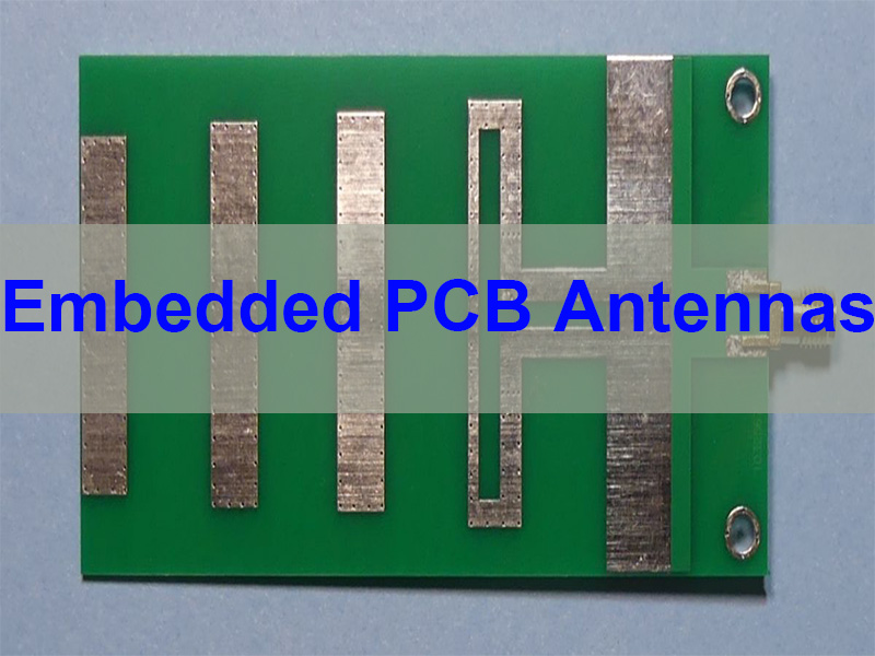
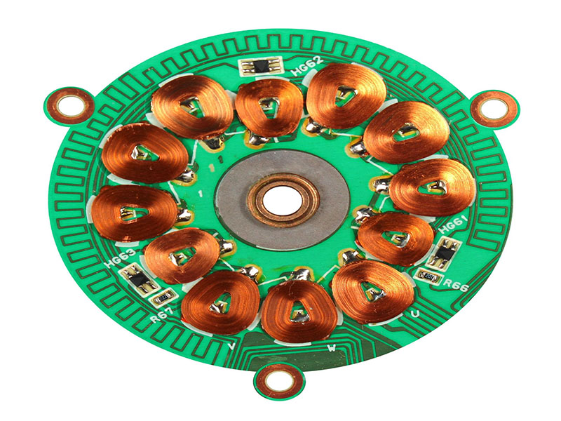
- PCB Stator Motors
Copper traces on the PCB act as motor windings, enabling compact and flat designs. - Axial Flux PCB Motors
These motors use axial magnetic flux and are known for high efficiency and thin form factors. - Micro PCB Motors
Designed for small devices requiring low power and minimal size. - Linear PCB Motors
Provide straight-line motion instead of rotation, useful in precision systems. - BLDC Motor PCB Systems
Use a dedicated BLDC motor PCB or controller for efficient electronic commutation. - Motor Control PCB Systems
The most common in industry, where the PCB controls an external motor.
| Type | Feature | Application |
|---|---|---|
| PCB Stator Motor | Flat winding | Compact devices |
| Axial Flux PCB Motor | Thin structure | High-efficiency systems |
| Micro PCB Motor | Small size | Portable electronics |
| Linear PCB Motor | Linear motion | Precision control |
| BLDC Motor PCB | Electronic commutation | Fans, drones |
| Motor Control PCB | External motor drive | Industrial systems |
Understanding these categories helps engineers select the right architecture for their product.
How Does a Motor Control PCB Drive and Regulate Motors?
A motor control PCB is responsible for managing motor behavior, including speed, direction, and stability. It acts as the central control platform in most PCB motor systems.
The control process includes:
- Receiving input signals
- Generating control logic
- Driving switching components
- Regulating current flow
- Monitoring feedback signals
Key control functions:
- Speed control through PWM
- Direction control via switching sequence
- Torque control through current regulation
- Protection against overcurrent and overheating
Core system structure:
| Section | Role |
|---|---|
| MCU / Controller | Logic processing |
| Gate Driver | Signal amplification |
| MOSFET Stage | Power switching |
| Feedback Circuit | Monitoring |
| Protection Circuit | Safety |
A well-designed motor control PCB ensures stable and efficient operation under different load conditions.
What Components Are Used in a Motor Driver PCB Design?
A motor driver PCB design integrates multiple components that work together to deliver controlled power to the motor.
Key components include:
- Controller IC / MCU – Executes control algorithms
- Gate Driver IC – Drives power switches
- MOSFETs / Power Devices – Handle current switching
- Current Sensors – Monitor load conditions
- Power Management Components – Stabilize voltage
- Protection Circuits – Prevent system damage
- Connectors – Provide electrical interfaces
| Component | Function |
|---|---|
| MCU | Control logic |
| Gate Driver | Switch control |
| MOSFET | Power handling |
| Sensor | Feedback |
| Protection | Safety |
| Connector | Interface |
The combination of these components defines the performance, efficiency, and reliability of the system.
How to Optimize PCB Layout for BLDC Motor Control?
PCB layout plays a critical role in motor performance, especially for BLDC systems where switching speed and current levels are high.
Key layout strategies:
- Minimize Current Loop Area
Reduces EMI and improves efficiency. - Separate Power and Signal Paths
Prevents noise interference. - Optimize Grounding Structure
Ensures stable reference and signal integrity. - Improve Thermal Management
Use copper pours and thermal vias. - Shorten Critical Signal Paths
Enhances control accuracy. - Use Proper Trace Width
Supports high current without overheating. - Plan Component Placement Carefully
Reduces switching losses and improves reliability.
| Layout Factor | Impact |
|---|---|
| Loop Area | EMI reduction |
| Grounding | Stability |
| Thermal Design | Heat control |
| Trace Width | Current capacity |
| Placement | Efficiency |
Proper PCB layout directly improves system reliability and extends product lifespan.
How to Integrate a PCB Motor Controller with Embedded Systems?
Integration with embedded systems is essential for modern motor applications.
Key integration areas:
- Power Interface – Stable voltage supply
- Signal Interface – PWM, UART, SPI, CAN
- Feedback System – Sensors and monitoring
- Protection Coordination – Fault handling
- Mechanical Integration – Connectors and layout
| Interface | Purpose |
|---|---|
| PWM | Speed control |
| UART | Communication |
| CAN | Networking |
| Sensor Input | Feedback |
A well-integrated system ensures smooth communication and reliable motor operation.
What Are Common PCB Motor Failures and How to Troubleshoot Them?
Common failures include:
- Power stage damage
- Thermal issues
- Signal interference
- Feedback errors
- Layout-related instability
Troubleshooting steps:
- Check power input
- Inspect switching devices
- Verify signals
- Analyze thermal performance
- Review PCB layout
| Symptom | Possible Cause |
|---|---|
| No motion | Power failure |
| Instability | Signal issue |
| Overheating | Poor layout |
| Noise | EMI problem |
A structured troubleshooting approach helps reduce downtime and improve reliability.
How to Choose the Right Motor Control PCB for Your Application?
Selecting the right PCB depends on multiple factors:
- Motor type
- Voltage and current requirements
- Control precision
- Environmental conditions
- System integration needs
- Space constraints
- Production volume
| Factor | Importance |
|---|---|
| Motor Type | Control method |
| Power Level | Design complexity |
| Environment | Reliability |
| Size | Layout density |
| Volume | Cost |
Choosing the right PCB ensures long-term performance and manufacturability.
In closing, PCB motor is a practical term describing motor systems where printed circuit boards play a central role in control, integration, and performance optimization. This article has explained how PCB motors work, their types, design considerations, and how motor control PCBs influence overall system behavior.
EBest Circuit (Best Technology) provides reliable PCB manufacturing, PCBA assembly, and engineering support for motor control applications. With strong experience in layout optimization, high-current design, and system integration, we help customers achieve stable and scalable production. For your next motor control project, pls feel free to contact us via sales@bestpcbs.com.
FAQs About PCB Motor
1. Is a PCB motor the same as a motor control PCB?
No. A PCB motor may refer to a motor structure that uses PCB-based windings or integration, while a motor control PCB is used to drive and regulate a motor. The two are related but serve different roles.
2. What are the main advantages of using a PCB motor system?
PCB motor systems offer compact design, high integration, improved consistency, and easier assembly compared to traditional motor and wiring setups.
3. Can a PCB motor be used in high-power applications?
Yes, but it depends on the design. For higher power, most systems use a motor control PCB to drive external motors rather than relying on PCB-based windings alone.
4. What should be considered when designing a PCB motor system?
Key factors include current capacity, thermal management, PCB layout, control method, and system integration to ensure stable and efficient operation.