An HSD connector can fit mechanically and still be wrong for the circuit. A working automotive data link needs the correct key code, pin assignment, cable construction, and PCB interface—not simply matching housing colors.
EBest Circuit (Best Technology) provides PCB fabrication and assembly for electronic products. Bringing board production and connector assembly together helps coordinate the footprint, soldering process, and inspection requirements. For the PCB/PCBA side of your HSD design, contact sales@bestpcbs.com.
What Is an HSD Connector Used For?
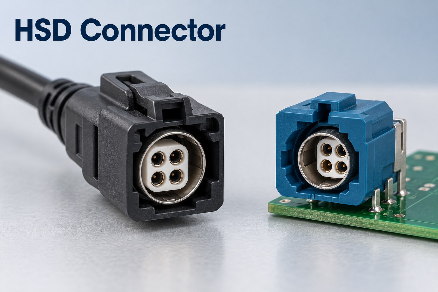
HSD means High-Speed Data. Its shielded contacts and locking housing carry data between vehicle modules while resisting interference and accidental disconnection.
| Connection | What HSD carries | Example |
|---|---|---|
| Head unit to display | Display data | Dashboard or rear-seat screen |
| Camera to ECU | Serialized image data | A compatible LVDS/SerDes camera link |
| Head unit to USB module | USB data and, with suitable wiring, power | Console USB connection |
| Networked modules | Ethernet data | A link with a compatible physical layer and cable arrangement |
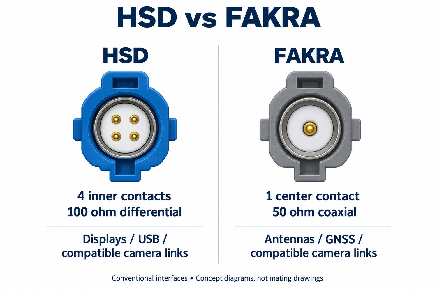
A conventional HSD interface has four inner contacts. They can serve two differential pairs, or a data pair plus supply conductors in a USB 2.0 arrangement. Four contacts do not always mean two active data pairs.
How Do HSD and FAKRA Connectors Differ?
Conventional HSD is a differential interconnect; conventional FAKRA is a coaxial interconnect. Choose according to the transceiver and transmission medium.
| Feature | Conventional HSD | Conventional FAKRA |
|---|---|---|
| Inner contacts | Four | One center contact |
| Typical impedance | 100Ω differential | 50Ω coaxial |
| Cable construction | Shielded quad or an application-specific pair arrangement | Coaxial cable |
| Typical links | Displays, USB, compatible differential camera links | GNSS, antennas, compatible coaxial camera links |
Both can carry digital signals. A camera link may use either differential wiring or coax, depending on its serializer/deserializer. An HSD-to-FAKRA adapter cannot by itself convert the electrical interface. Board-side considerations are covered in our FAKRA PCB connector guide.
What Do HSD Connector Colors and Key Codes Mean?
The color identifies a mechanical key code, helping assemblers distinguish ports and avoid incorrect mating. The following are common HSD color–code combinations.
| Code | Housing color |
|---|---|
| A | Black |
| B | Cream white |
| C | Blue |
| D | Claret violet |
| E | Green |
| F | Brown |
| Z | Water blue; neutral coding within the specified mating group |
Other directional variants use G—blue gray, H—heather violet, J—beige, K—curry yellow, L—yellow green, M—pastel orange, and O—light green. Their mating direction and compatibility follow the specific connector drawing.
The application is assigned to the port, not standardized by its color. Display, camera, USB, and Ethernet connections can use different keys to keep neighboring sockets distinct. A vehicle manufacturer may assign one color to one function on a particular platform; that assignment should not be carried over to another vehicle.
For a replacement USB cable, match the vehicle’s port code and USB wiring. For a camera cable, match the camera/ECU interface and pin assignment. Blue alone does not identify USB 3.x, and green alone does not identify Ethernet.
How Do You Read an HSD Connector Pinout?
Read the pin numbers together with the signal names and the drawing’s viewing direction. Opposite ends of a cable do not necessarily connect matching numbers.
The following USB 2.0 wiring example uses one pair for data and two conductors for power. It illustrates one configuration; vehicle-specific pin assignments may differ.
| Signal | Side A contact | Side B contact |
|---|---|---|
| D+ | 1 | 4 |
| +5 V supply | 2 | 3 |
| D− | 3 | 2 |
| Ground | 4 | 1 |
Here, A1 connects to B4 while preserving D+. Connecting 1-to-1 would join different functions. Confirm whether the drawing shows the mating face, cable side, or PCB side before locating these contacts.
The metal shield is a separate connection whose grounding follows the system design. Do not silently substitute it for a numbered ground conductor.
What Determines an HSD Connector’s Data Rate?
The transceivers set the operating rate; the connector, cable, and PCB must preserve enough signal quality at that rate. Longer cables increase loss, impedance discontinuities cause reflections, and unequal pair delays distort differential signals.
A frequency rating in GHz describes an electrical operating range; a data rate in Gbps describes bits transmitted per second. They cannot be substituted for one another when selecting a connector.
A useful calculation: read a reflection specification:
For example, if return loss is 17 dB at the frequency being evaluated, the reflected-power fraction is calculated as follows.
Reflected power / incident power = 10^(−17/10) ≈ 2%
At 20 dB, that fraction falls to 1%. Higher return loss means less reflection. These figures describe reflected signal power, not packet loss or bit-error rate.
Insertion loss measures a different problem: how much signal is lost through the channel. A usable high-speed link must satisfy both loss and reflection limits, plus timing requirements, across its operating band. A connector rating alone cannot establish the maximum cable length.
Which HSD Cable Fits Your Connection?
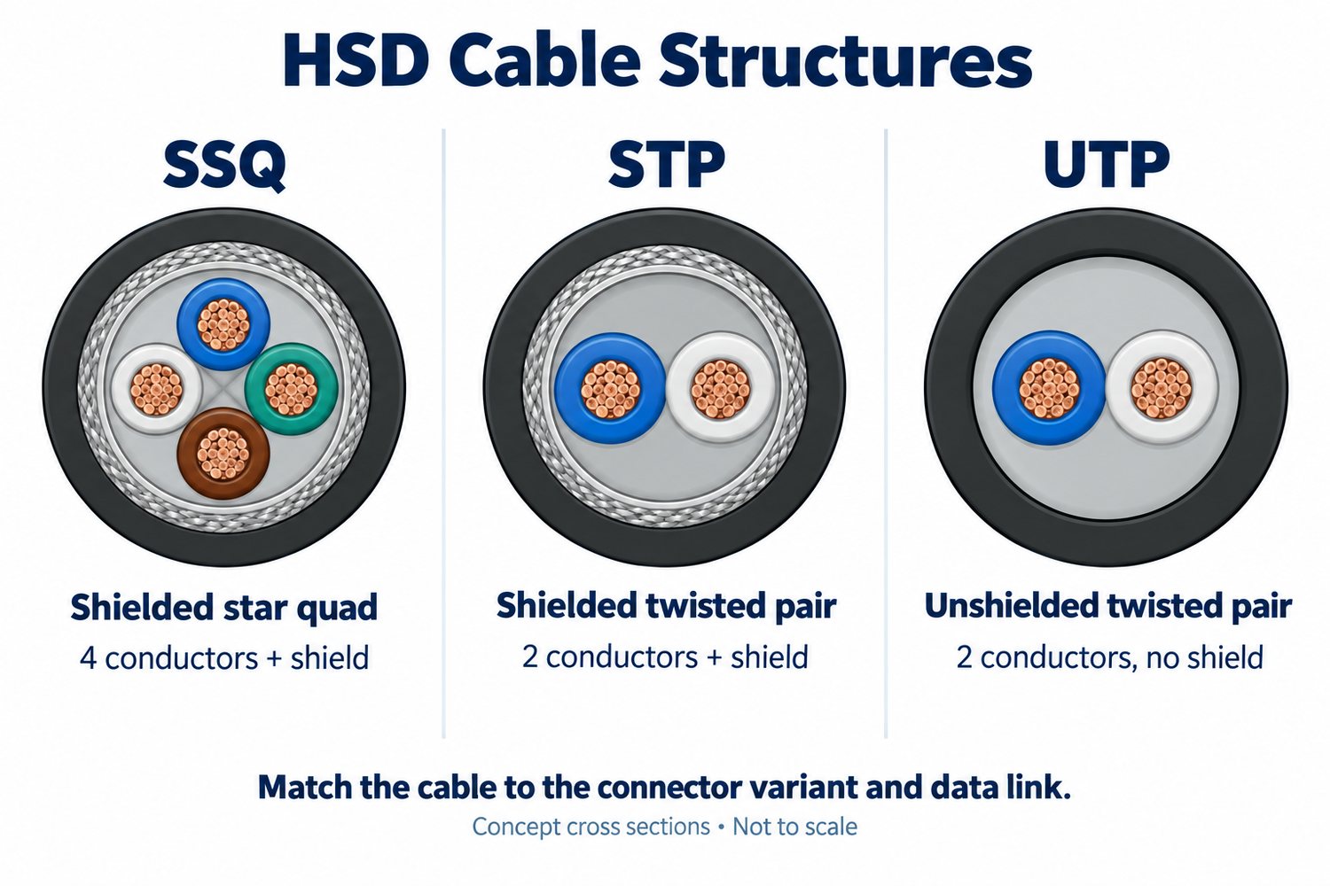
Start with the required pair count and cable impedance, then choose shielding and mechanical protection for the installation. The main constructions serve different links.
| Cable construction | Structure | Appropriate use |
|---|---|---|
| Shielded star quad, SSQ | Four conductors twisted together under a shield | Four-contact HSD assemblies designed for star-quad cable, including compatible display and USB links |
| Shielded twisted pair, STP | Two conductors twisted together under a shield | A compatible single-pair link; HSDt offers a two-contact version |
| Unshielded twisted pair, UTP | One twisted pair without a shield | A specifically designed unshielded link, such as a suitable HSDt Ethernet implementation |
Cable construction follows the chosen assembly, not the HSD name alone. A coaxial camera cable is a different transmission medium.
Match the cable to where it will work:
- Behind a dashboard: route a shielded assembly within its specified bend radius; avoid crushing the cable at clips and brackets.
- At a mirror or bumper camera: use a sealed connector assembly and a jacket rated for the installation’s water, temperature, and abrasion exposure.
- Across a moving joint: require a repeated-flex rating; a cable that bends during installation may not survive continuous movement.
- Over a longer route: evaluate attenuation at the signal frequencies. If power shares the harness, also check supply drop using ΔV = I × R_loop; loop resistance includes the outgoing and return paths.
The cable’s conductor size and outer diameter must fit the connector’s contacts, ferrule, and seals. An electrically suitable cable can still be unsuitable for the selected termination.
How Should an HSD Connector Be Integrated into a PCB?
Design the connector launch and PCB routing as one signal path. Use the exact part footprint and the intended PCB material and stackup when setting differential impedance.
With a right-angle HSD header, equal PCB trace lengths may still leave unequal total delays. Its signal pins can have different lengths. Account for this pin delay when designing the footprint and routing compensation for the actual board stackup. Match the complete connector-to-PCB signal paths.
Keep the reference plane continuous beneath the pair, including the connector escape. Include ESD devices, coupling capacitors, and any common-mode choke in the channel assessment; their pads and parasitics also affect the signal.
For assembly, distinguish SMD from pin-in-paste headers. Shield tabs, hole geometry, paste volume, and housing temperature limits must suit the selected soldering process. Mechanical support should keep harness loads from stressing signal joints.
FAQs About HSD Connectors
Can one four-contact HSD connection carry a complete USB 3.0 link?
A complete USB 3.0 connection needs more conductors than a single four-contact HSD provides. One implementation uses double HSD: one cable for USB 2.0 data and supply, and a second for the SuperSpeed pairs. Housing color does not establish USB capability.
Are HSD connectors waterproof?
Only suitably sealed versions. For an exterior camera, use the rated connector-and-cable assembly in its specified mating condition; an interior HSD housing is not automatically waterproof.
Can HSD connectors from different manufacturers mate?
Compatible versions can, but the interface dimensions, key code, pin mapping, and electrical ratings must agree. Identical housing colors alone do not establish interchangeability.
Does HSD+2 mean two data contacts?
No. It adds two power contacts alongside the conventional HSD data interface. HSDt is the distinct two-data-contact variant.
Why can an HSD cable pass continuity testing but fail in operation?
Continuity verifies the conductive paths, not high-frequency performance. Excessive loss, reflections, damaged shielding, or pair imbalance can still prevent reliable communication.
Once your HSD connector and cable interface are defined, EBest Circuit can support the associated PCB fabrication and assembly. Discuss your board stackup and connector mounting requirements with sales@bestpcbs.com.