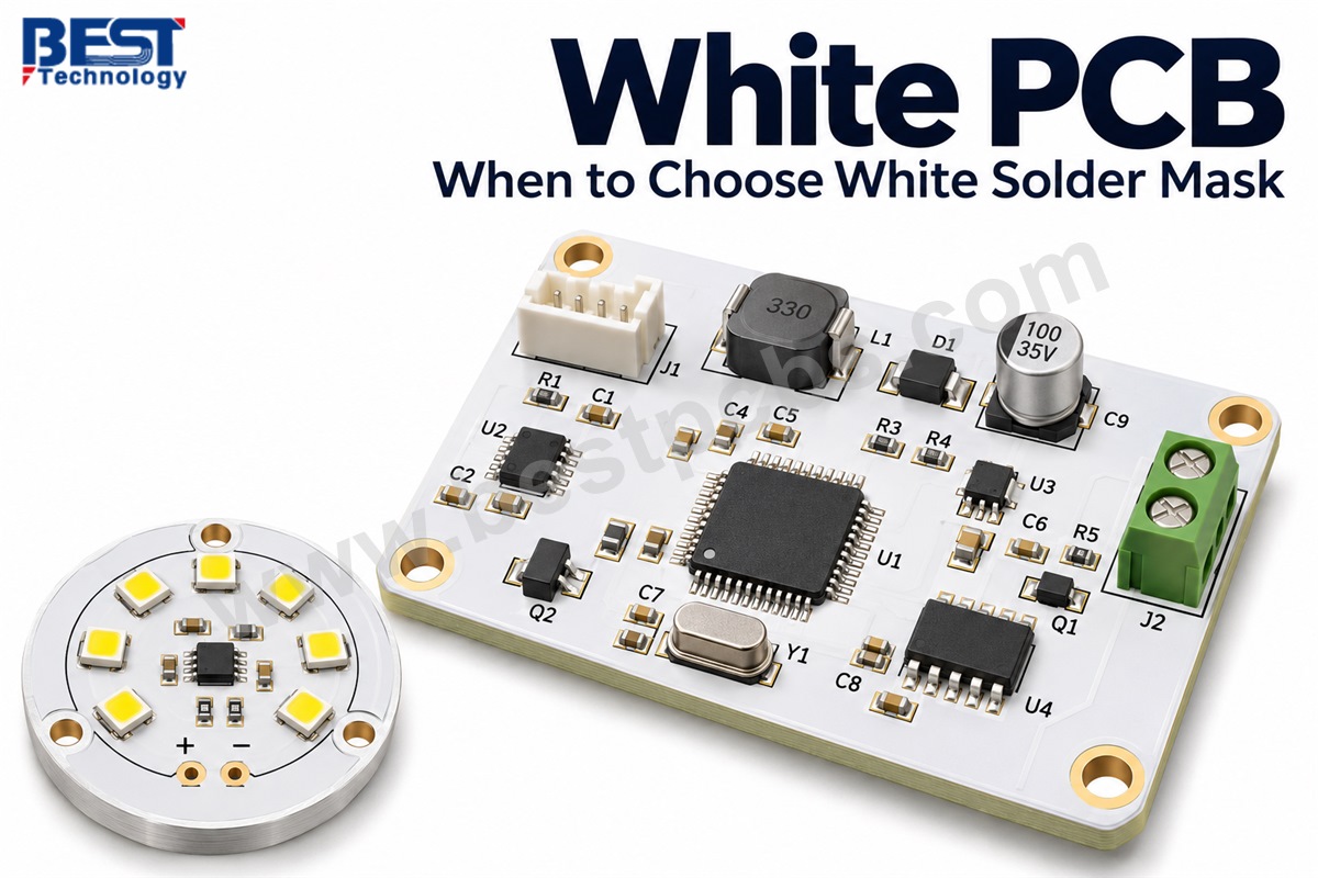
A white PCB gets its color from the solder mask. Both FR-4 and aluminum-based boards can have a white surface. White solder mask is useful when the board reflects light inside an LED fixture or remains visible in the finished product.
In LED lighting, the exposed white surface can return light toward a diffuser or reflector. In visible electronics, it can complement a white enclosure and make dark markings easier to read. For a board hidden inside an opaque housing, white may offer little practical benefit unless the surface has an optical function.
At EBest Circuit (Best Technology), we provide PCB fabrication and assembly for projects ranging from LED modules to electronic control boards. Customers can order bare boards or complete assemblies, with the material and manufacturing process selected around the product’s electrical, thermal, and appearance requirements.
Key Takeaways
- White describes the solder mask, not the substrate. FR-4 and aluminum PCBs can both use white solder mask.
- Light reflection supports LED applications. Selected high-reflectance white solder masks achieve approximately 90–95% reflectance near 450 nm, helping return incident light into the optical system.
- Board construction controls the main heat-transfer path. The dielectric, copper layout, and heat sink matter more than solder mask color.
- Assembly heat can change the appearance. Color-sensitive products need evaluation after the complete soldering process.
- Black silkscreen usually provides clear contrast. Label placement also determines whether markings remain readable after assembly.
- White surfaces reveal some residues and rework marks. Inspection requirements should reflect the board’s visibility in the finished product.
- White boards can carry a manufacturing premium of 20–30%. The actual difference depends on the mask grade, quantity, and inspection requirements.
What Is a White PCB?
A white PCB is a printed circuit board with white solder mask over selected areas of its outer copper circuitry. The mask helps protect covered conductors and keeps solder away from areas that should remain unsoldered. Openings expose pads, test points, and other electrical contacts.
The board underneath can use FR-4, an aluminum base, or another compatible construction. Copper carries the electrical signals, while the substrate provides mechanical support and insulation. Silkscreen identifies components and connections, and the surface finish protects exposed copper pads. These features remain separate from the solder mask color.
Common applications include:
- LED light engines. Exposed white mask between the LEDs can reflect light toward the diffuser.
- Display backlights. White mask can return light into the backlight cavity when the PCB forms part of its reflective surface.
- Visible circuit boards. Motherboards and control boards behind clear covers may use white to match the enclosure or highlight the components.
- Decorative lighting products. White boards can blend into light-colored housings where the circuit board remains partly exposed.
White PCB therefore describes a surface choice rather than a single board technology. A multilayer control board and a single-layer aluminum LED board can share the same color while serving very different purposes.
Key Characteristics and Benefits of a White PCB
White PCBs offer three main benefits: light reflection, a clean appearance in exposed electronics, and clear contrast with dark markings. Their value depends on how the board functions inside the product.
- Light reflection. White solder mask can redirect light that reaches the board between LEDs. This is useful in shallow lighting fixtures and backlights where the PCB forms part of the optical cavity.
- Appearance. A white surface can complement white plastic housings, transparent covers, and minimalist product designs. The board becomes part of the visible assembly rather than a background manufacturing detail.
- Readable markings. Black component references, connector labels, and polarity symbols stand out against white solder mask. This helps during assembly, troubleshooting, and servicing.
- Visual separation of components. Dark packages and connectors are easy to distinguish against a light background, which can help technicians locate parts during manual checks.
The electrical function of the board still comes from its circuit design and construction. White solder mask does not increase current capacity or improve signal integrity by itself. Its strongest advantages are optical and visual, so those should guide the color decision.
How Does White Solder Mask Affect LED Light?
White solder mask improves light utilization by reflecting light that reaches the exposed PCB between the LEDs. Selected high-reflectance white solder masks can achieve approximately 90–95% reflectance near 450 nm, making them useful in LED light engines, display backlights, and other assemblies where the board forms part of the reflective surface.
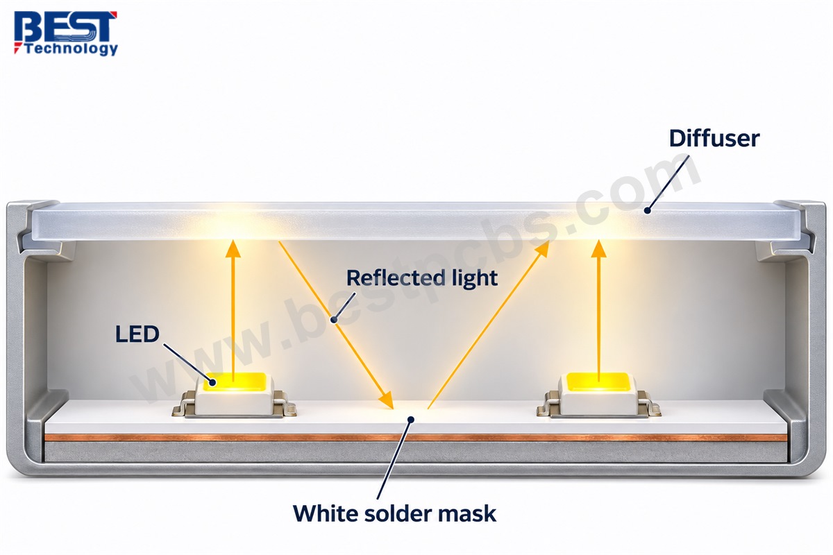
In a shallow LED fixture, some light travels directly toward the diffuser, while some strikes the PCB first. White solder mask returns part of that light into the optical cavity, where it can contribute to the fixture’s output. When a separate reflector covers most of the board, less light reaches the mask, so changing its color may provide little improvement.
The reflectance percentage describes the coating’s response to incident light; it does not represent the percentage increase in lamp brightness. The finished result also depends on exposed board area, LED placement, coating thickness, and the diffuser or reflector geometry.
Should a White LED PCB Use FR-4 or an Aluminum Base?
FR-4 suits LED circuits that need flexible routing or integrated control electronics. An aluminum base is often a better candidate when the board must conduct heat from the LEDs into a housing or heat sink.
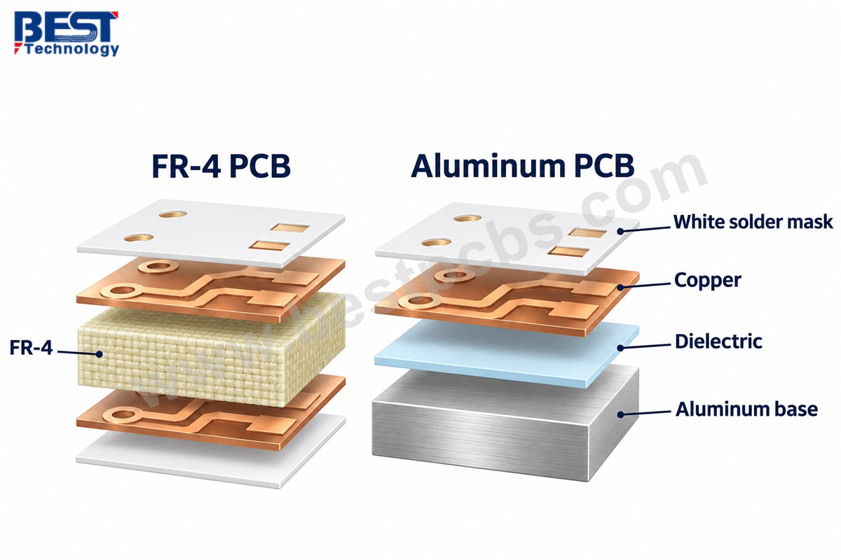
The decision comes from the electrical layout and heat-transfer requirements. Both constructions can use white solder mask.
| Selection factor | White FR-4 PCB | White aluminum PCB |
|---|---|---|
| Basic construction | Glass-reinforced epoxy laminate with copper circuitry | Copper circuitry, insulating dielectric, and aluminum base |
| Routing flexibility | Well suited to multilayer and complex circuits | Commonly used for simpler LED layouts; specialized constructions are available |
| Main thermal approach | Copper spreading, thermal vias, and suitable mounting | Heat transfer through the dielectric into the metal base |
| Typical fit | LED controllers, indicator boards, mixed electronic circuits | Light engines and LED modules mounted to a thermal housing |
| Main design concern | Providing sufficient heat removal within the available layout | Matching dielectric performance and mounting contact to the heat load |
Our FR-4 PCB manufacturing covers single-sided through multilayer constructions. For lighting designs that need a metal-backed thermal path, our metal core PCB options include aluminum-based constructions.
In an aluminum PCB, heat travels from the copper circuit through an electrically insulating dielectric before reaching the metal base. The dielectric’s thickness and thermal conductivity therefore affect how easily heat leaves the LED area. Its simplified through-thickness thermal resistance is:
Rth=tkA
Here, Rth is thermal resistance in K/W, t is dielectric thickness in meters, k is thermal conductivity in W/(m·K), and A is the effective heat-transfer area in square meters.
For example, a 75 µm dielectric with a thermal conductivity of 2 W/(m·K) and an effective heat-transfer area of 100 mm² has a calculated resistance of:
Rth=75×10−62×100×10−6=0.375 K/W
Increasing the dielectric thickness to 150 µm doubles this value to 0.75 K/W when conductivity and area remain unchanged. This explains why a thicker insulating layer can restrict heat transfer even when both boards use the same aluminum base.
The calculation represents the dielectric alone. LED package resistance, heat spreading, solder connections, and contact with the heat sink also affect the operating temperature. For material selection, the dielectric must provide the required electrical insulation while keeping thermal resistance within the design’s limits.
Why Can White Solder Mask Yellow After Reflow?
White solder mask can yellow because heat changes the coating’s resin system or other ingredients. The amount of discoloration depends on the formulation, curing process, temperature, and duration of exposure.
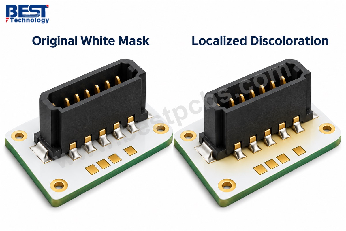
Repeated heating can make the change more noticeable. A double-sided SMT board may pass through reflow twice, while a connector repaired by hand receives additional local heat. The location of the discoloration helps identify what happened:
- A warmer shade across the board suggests reviewing the material, curing conditions, and overall thermal exposure.
- Yellowing around a repaired component suggests checking the local rework temperature and heating time.
- Patchy deposits around joints may be flux residue or contamination rather than a permanent change in the solder mask.
These differences matter because the corrective actions are different. Cleaning may remove residue, but it cannot reverse a heat-induced change inside the coating.
Long-term operating heat also matters. An LED module that runs warm for extended periods needs a mask suited to that exposure. Where appearance is tightly controlled, an agreed color-difference measurement such as ΔE₀₀ can supplement visual comparison with a reference sample.
Should You Use Black Silkscreen on a White PCB?
Yes. Black silkscreen is usually a clear, practical choice because its contrast makes component references, polarity marks, and connector labels easier to read.
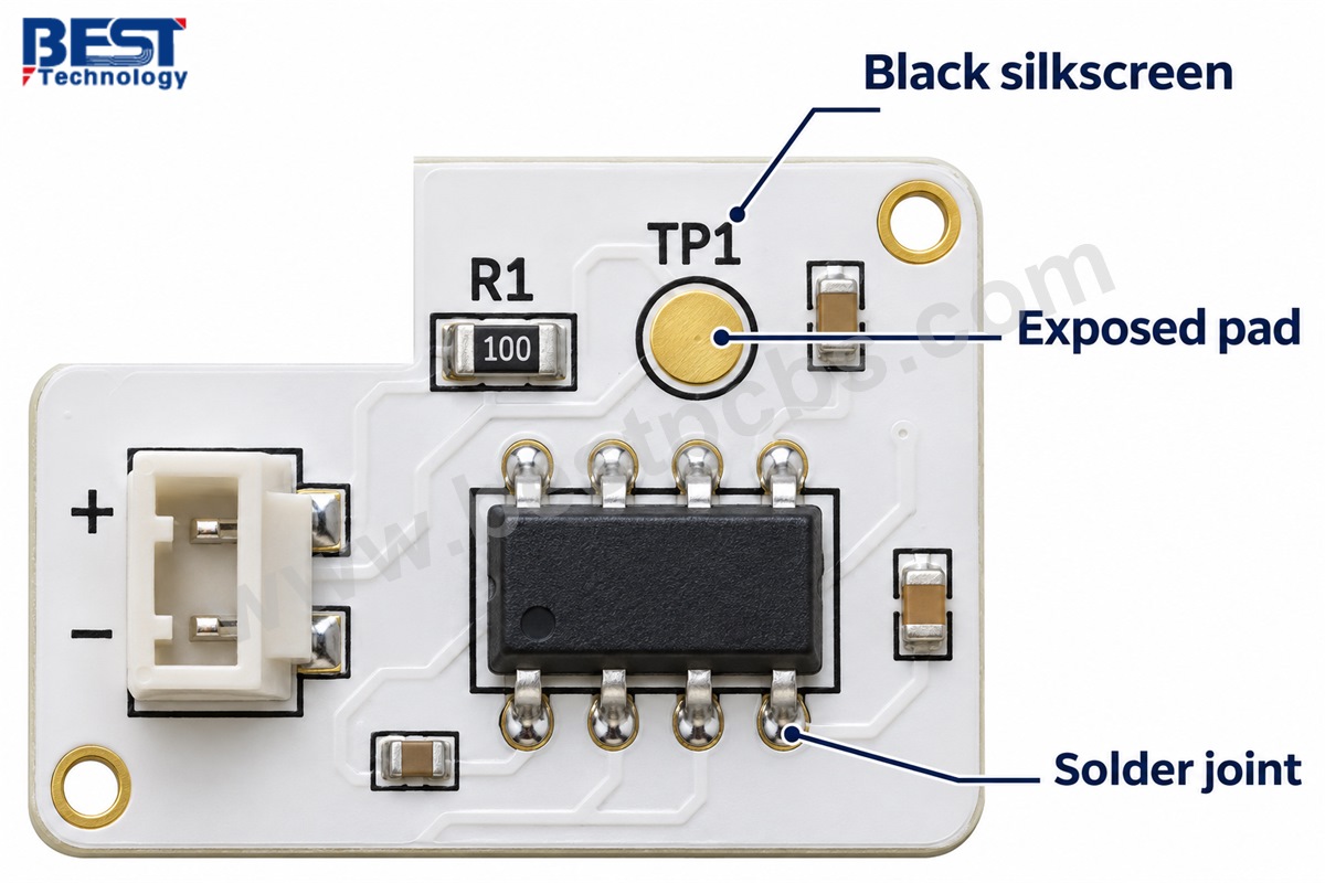
White legend on white mask provides little contrast. Other dark colors may work, but black is a straightforward option when readability is the priority. Our silkscreen and solder mask color guide shows compatible combinations.
Placement matters as much as color. A clear label on the bare board becomes useless if a connector or tall component covers it after assembly. Useful marking practices include:
- Connector labels beside the installed connector, where technicians can read them with cables attached.
- Polarity marks near the relevant pad or component, without covering solderable areas.
- Test-point identification outside crowded component outlines, where probes and operators have access.
- Revision and part numbers in a visible location, so the finished assembly can be identified.
On reflective LED boards, large printed areas can also reduce the exposed white surface. Essential identification can often sit near the edge or outside the main optical area, keeping the markings readable without occupying useful reflective space.
How Does White Solder Mask Affect Assembly Inspection?
White solder mask can reduce contrast around shiny solder joints under some inspection lighting. The assembly team may need to adjust illumination or inspection settings so joint boundaries remain clear.
Dark components are often easy to see against white, but reflective metal can appear similarly bright to the background. Good component contrast therefore does not guarantee good solder-joint contrast. Changing an existing board from green to white may leave the copper layout unchanged while altering the camera image.
The main checks are:
- Visible joint boundaries, especially where reflections obscure the transition between solder, pad, and mask.
- Component orientation and polarity, using markings that remain distinguishable under production lighting.
- Surface residue and rework marks, evaluated separately from solder-joint acceptance.
- Mask coverage around pads, where missing or damaged mask may affect the intended separation.
A clean-looking surface alone does not establish electrical reliability. Visual appearance, solder quality, and circuit function each require an appropriate check. Likewise, top-side optical inspection cannot establish the condition of every hidden solder connection beneath a component.
What Are the Drawbacks of a White PCB?
The main drawbacks are discoloration, visible surface marks, potentially more demanding optical inspection, and added cost for special materials or appearance requirements.
- Discoloration. Some white solder masks turn yellow after repeated heating or extended operation at elevated temperatures. This is particularly noticeable in exposed electronics and lighting modules.
- Visible residue. Flux stains, handling marks, and local rework discoloration can stand out on a light background, even when the board remains electrically functional.
- Inspection challenges. Bright solder joints can blend into the surrounding mask under certain lighting conditions.
- Shade variation. Different white formulations can have different tones and gloss levels. Adjacent boards in the same product may make small differences more noticeable.
- Fine-pitch manufacturing limits. The selected mask and imaging process determine which narrow webs and clearances can be produced consistently.
- Cost. White boards can cost 20–30% more to manufacture than standard green boards of the same construction. The difference depends on the white solder mask grade, order quantity, and any additional color or optical inspection requirements.
These drawbacks help define when white’s benefits justify additional control. A visible lighting module may need that attention, while a concealed control board may gain little from it.
White PCB vs. Black PCB: Which Should You Choose?
White generally suits products that benefit from visible-light reflection or a light-colored appearance. Black suits dark visual designs and applications where reduced visible-light reflection is desirable.
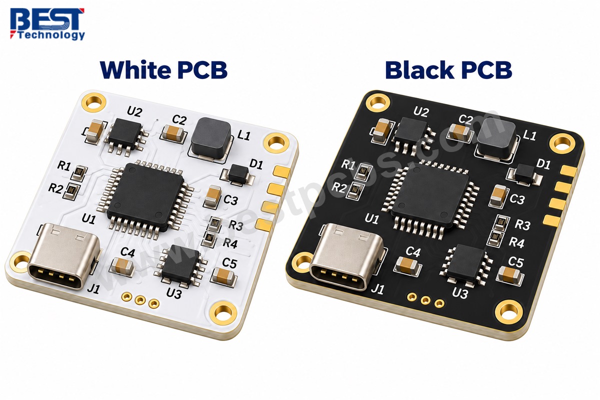
The useful question in a white PCB vs. black PCB comparison is what the exposed board surface needs to do.
| Decision factor | White PCB | Black PCB |
|---|---|---|
| Product appearance | Matches light-colored enclosures and exposed white assemblies | Matches dark enclosures and dark visual themes |
| Visible-light behavior | Can provide useful reflection with a suitable mask | Usually reflects less visible light |
| Readable legend | Black or another contrasting dark color | White or another contrasting light color |
| Surface appearance concerns | Yellowing, stains, and local heat marks | Dust, fingerprints, and some residues |
| Optical use | Reflective areas around LEDs and inside backlights | Selected designs requiring reduced stray visible light |
| Electrical performance | Determined by circuit design and construction | Determined by circuit design and construction |
| Thermal selection | Requires evaluation of the actual thermal path | Requires evaluation of the actual thermal path |
For LED lighting, white is a strong candidate when the PCB helps return light toward the output. For a visible control board, enclosure styling may be the deciding factor.
What Affects the Price of a White PCB?
White PCBs can cost 20–30% more than comparable green PCBs, although the actual premium varies with the solder mask material, production quantity, and inspection requirements. Board construction still determines much of the total price: an aluminum LED board, a two-layer FR-4 board, and a multilayer control board involve different materials and manufacturing processes.
Our overview of PCB board pricing explains how construction and order requirements influence the quotation. For white boards, the main cost drivers include:
- Board construction. Substrate, layer count, copper thickness, and hole structures influence material consumption and fabrication work.
- Solder mask grade. Standard white serves a different requirement from a high-reflectance formulation selected for LED performance.
- Order quantity and panel utilization. Small batches spread setup costs across fewer boards, while long strips or irregular outlines may leave more unused panel area.
- Appearance and optical requirements. Shade matching, reflectance measurements, and additional cosmetic inspection increase the work needed to qualify and accept the boards.
- Assembly scope. Component sourcing, placement, soldering, and testing contribute to the price of a populated board and should remain consistent when comparing quotations.
The most practical way to control cost is to match the specification to the product. Standard white may be sufficient for appearance, while a reflective grade is justified when the PCB contributes to light output. If only one side remains visible, the shade requirement can apply to that face.
Why Choose EBest Circuit as Your White PCB Manufacturer?
EBest Circuit combines PCB fabrication, component sourcing, and assembly, allowing customers to develop the bare board and populated product within one manufacturing project.
Our capabilities support the different requirements of white LED boards and white control electronics:
- FR-4 manufacturing. Our published capability range covers 1–32 layers, supporting both simple circuits and more complex routing requirements. White-mask suitability is reviewed against the selected construction.
- Metal core PCB production. We manufacture aluminum-based boards for lighting applications, with prototype and production support.
- Integrated assembly. Our services cover SMT and mixed SMT/through-hole assemblies, with consigned components, partial turnkey, or full turnkey supply.
- Small and fine-pitch components. Documented assembly capabilities include 01005 components and 0.25 mm-pitch BGA packages, subject to the actual layout and package requirements.
- Inspection and testing. Available methods include 3D SPI, AOI, X-ray inspection, and functional testing to an agreed plan.
Our surface mount PCB assembly service brings component preparation, placement, soldering, and inspection into the same production scope.
For a white LED module, this coordination connects the board material with the assembly process and finished appearance. For a control board, it connects routing and component requirements with manufacturability. The project can then progress from a representative prototype to production using the approved construction and build requirements.
What Files and Specifications Do You Need for a White PCB Quote?
A white PCB quotation needs the fabrication files, board construction, quantity, and solder mask requirements. Assembly orders also need component and placement information.
The most useful starting package includes:
- Gerber and drill files, together with the board outline.
- Construction details, including substrate, layer count, finished thickness, and copper weight.
- Solder mask and silkscreen colors, identifying the requirement for each side.
- Surface finish, such as ENIG or lead-free HASL.
- Order quantities, covering the immediate prototype batch and expected production volume.
- Assembly files, including the BOM, pick-and-place data, and assembly drawing.
- Functional or appearance requirements, including test instructions and any optical or color targets.
The white finish should be described by its purpose. “White for appearance” is different from “white with a defined reflectance at the operating wavelength.”
For a lighting module, useful additional information includes the LED part number, drive current, mounting arrangement, and intended housing or heat sink. These details help connect the PCB construction to the assembled product.
If only part of the board remains visible, a marked drawing can identify that area. A physical color reference is also more useful than a screen image when a close shade match is required, because display settings and lighting can change how the same white surface appears.
Frequently Asked Questions About White PCBs
Can I change a green PCB to white without changing the circuit?
Often, yes. The copper layout and drill data may remain unchanged. The manufacturer still needs to check mask clearances, narrow webs, and compatibility with the selected white material. Silkscreen color and inspection settings may also need adjustment.
Does white solder mask improve PCB heat dissipation?
White solder mask should not be selected as a thermal solution. The substrate, dielectric, copper layout, and mounting interface determine the main conductive heat path. Visible color also does not establish a coating’s infrared emissivity.
Can white PCBs use ENIG or lead-free HASL?
Yes, when the selected mask and manufacturing process support that finish. ENIG provides a relatively flat pad surface, while HASL can introduce more surface variation. Package and assembly requirements should guide the finish choice.
Can one side be white and the other side another color?
Yes, when the fabricator supports the combination. The fabrication notes should identify the color on each side. Separate colors may involve additional processing, so the requirement belongs in the initial quotation request.
Is a white PCB always an aluminum PCB?
No. White describes the external solder mask. Single-sided, double-sided, and multilayer FR-4 boards can also have white surfaces. Aluminum identifies the underlying construction and serves a different purpose.
Does a white PCB need cleaning after assembly?
Cleaning depends on the flux process and product requirements. Visible boards may need residue removal for appearance, while sensitive circuits or subsequent coatings may impose separate cleanliness requirements. “No-clean” flux does not automatically satisfy every finished-product specification.
White PCB is a practical choice when the exposed surface contributes to LED reflection or product appearance. The material underneath still needs to meet the circuit’s routing, thermal, and mechanical requirements, while the solder mask must remain suitable through assembly and use.
EBest Circuit provides PCB fabrication and assembly for white FR-4 boards and aluminum LED modules. Send your Gerber files, BOM, quantities, and optical or appearance requirements to sales@bestpcbs.com for a project-specific review and quotation.