What does OL mean on a multimeter? In most cases, OL tells you that the meter cannot display a normal numeric result under the present test conditions. In resistance and continuity modes, it usually means an open circuit or a resistance above the available range. In voltage or current mode, it more often means the measured value exceeds the selected range. The exact interpretation depends on the function, range, lead ports, probe contact, and meter model.
OL is therefore an indication, not a complete diagnosis. It can be perfectly normal when the probes are separated, useful evidence of a broken connection, or a warning that the selected range is too low. This guide shows how to read it by mode and how to isolate the cause without creating a new fault.
What Does OL Mean on a Multimeter?
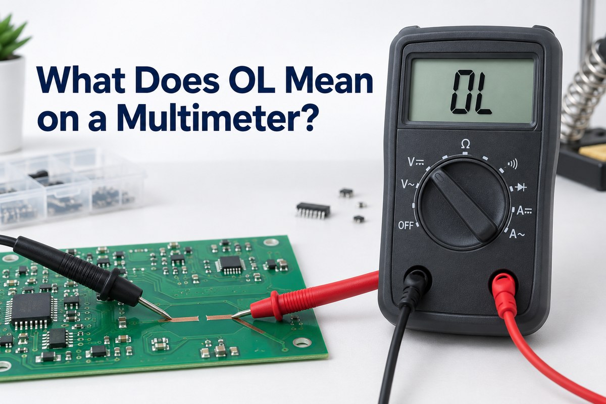
Meter manufacturers use OL as a compact display message for conditions such as overload, over limit, or a value outside the present measurement range. When checking resistance or continuity, the same display commonly corresponds to an open path or effectively infinite resistance. The manual for your meter remains the final reference because display conventions and test thresholds vary.
| Meter mode | What OL usually means | First check |
| Resistance (Ω) | Open circuit or resistance above the selected/measurable range | Power off, probe contact, range, and component isolation |
| Continuity | No conductive path below the meter’s continuity threshold | Broken wire, open fuse, switch state, trace, or connector |
| Diode test | Reverse bias, open junction, poor contact, or voltage drop beyond the test limit | Probe polarity and a second reading with probes reversed |
| Voltage | Input above the selected range, especially on a manual-ranging meter | Correct AC/DC function, ports, and a safely higher range |
| Current | Current above the selected range or an invalid measurement setup | Correct jack, fuse, series connection, and current rating |
Do not treat OL as proof that a part has failed until you confirm the selected mode and repeat the test correctly. A separated probe, oxidized terminal, lifted PCB pad, open via, blown fuse, or simply the wrong range can all produce the same two letters.
What Does OL Mean on a Multimeter When Measuring Resistance?
When people ask what does OL mean on a multimeter when measuring resistance, the practical answer is: the meter sees more resistance than it can show on the current range. With the probes separated, this is expected because there is no conductive path between them. Across a component or conductor that should be connected, OL suggests an open path, poor probe contact, or an out-of-range resistance.
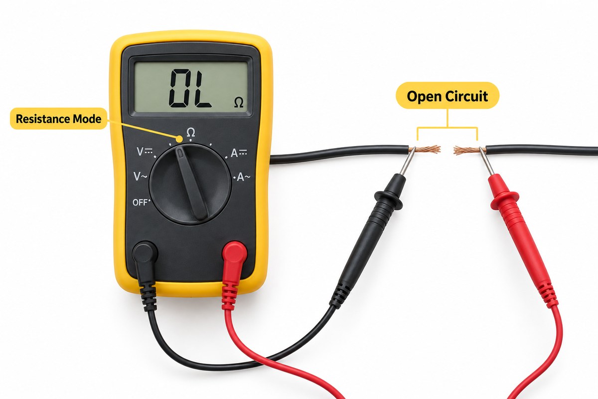
Before measuring resistance, disconnect power and discharge capacitors. Fluke’s resistance guidance notes that an unconnected meter can normally show OLΩ and that the component may need to be isolated from parallel circuit paths for a meaningful result. In-circuit measurements can be affected by other resistors, semiconductors, contamination, and stored charge.
Use this sequence:
- Turn the circuit off and verify it is de-energized.
- Discharge capacitors using an appropriate safe procedure.
- Put the black lead in COM and the red lead in the V/Ω jack.
- Select Ω and, on a manual-ranging meter, begin with a higher range.
- Touch the probes together. A low reading confirms that the meter and leads can complete a path.
- Measure the component or conductor with clean, firm probe contact.
- If OL remains, isolate one end of the component or divide the circuit into sections.
A resistor that is intentionally above the meter’s range can also display OL even though it is not electrically open. Check the resistance value, expected tolerance, and the meter specification before condemning the part.
What Does OL Mean on a Multimeter When Measuring Continuity?
For what does OL mean on a multimeter when measuring continuity, OL normally means the tested path does not meet the meter’s continuity threshold. In plain terms, the path is open or too resistive for the beeper to recognize as continuous. Klein Tools’ MM400 instructions, for example, state that an open circuit displays OL in continuity mode.
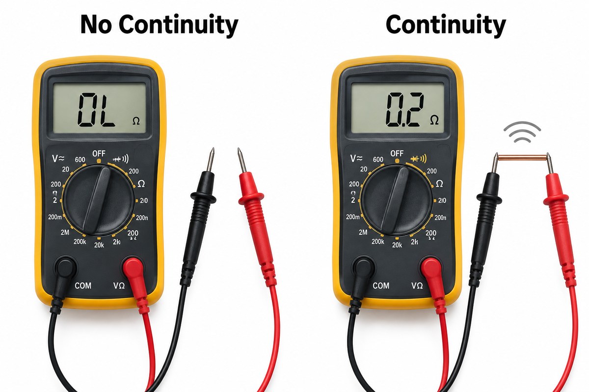
Continuity mode is useful for finding opens in:
- Wires, cables, and connectors
- Fuses and closed switches
- PCB traces, plated through-holes, and vias
- Solder joints and jumper links
- Ground paths that should be directly connected
No beep does not always mean absolute infinite resistance. Each meter has a model-specific beep threshold. A path with tens or hundreds of ohms may be electrically connected yet remain above that threshold. Switch to resistance mode when you need a numeric value rather than a quick pass/fail indication.
For PCB troubleshooting, begin at two known points on the same net and then shorten the distance between probes. This divide-and-test method helps locate an open trace, cracked via, damaged connector, or suspect solder joint. For production-level context, see our overview of PCB testing methods.
What Does OL Mean on a Multimeter When Measuring Voltage?
If you search what does OL mean on a multimeter when measuring voltage, the most common explanation is an over-range condition. The input is above the selected voltage range, or the meter is on the wrong function. An auto-ranging meter usually changes range automatically, while a manual-ranging model requires you to select a range above the expected value.
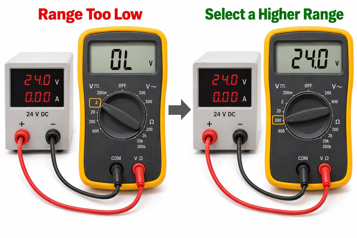
Check these items before re-measuring:
- Select DC voltage for DC supplies and batteries, or AC voltage for AC sources.
- Keep the black lead in COM and the red lead in the voltage/ohms jack.
- On a manual-ranging meter, start at a range above the maximum expected voltage.
- Confirm the meter, probes, and accessories carry the required voltage and CAT rating for the environment.
- Stop if the source may exceed the instrument’s maximum input rating.
Never solve a voltage OL by moving the red lead to a current jack. The current input is a low-resistance path intended for a series connection. Placing it directly across a voltage source can blow the meter fuse, damage equipment, or create an arc hazard.
What Does OL Mean in Current and Diode Modes?
In current mode, OL can indicate that current exceeds the selected range. Current must be measured with the meter connected in series, using the correct fused input and function. If you do not know the expected current, begin with the highest suitable range and follow the meter manufacturer’s instructions. Do not place a meter in current mode directly across a power source.
In diode mode, an OL reading can be normal in one direction because a healthy diode blocks reverse current. A typical test checks both polarities:
- A normal silicon diode generally shows a forward-voltage reading in one direction and OL in the reverse direction.
- OL in both directions can indicate an open diode, poor contact, an in-circuit parallel path issue, or a junction outside the meter’s test capability.
- A very low reading in both directions can indicate a shorted diode.
These patterns are diagnostic clues, not universal acceptance limits. Package type, device technology, circuit connections, and meter test voltage all matter. Our rectifier diode guide explains how diode behavior relates to PCB power paths.
How Do You Fix an Unexpected OL Reading?
There is no single “OL fix.” The goal is to determine whether the display is expected for the selected mode or caused by the setup, test point, or circuit.
- Read the mode first. Resistance, continuity, diode, voltage, and current modes interpret OL differently.
- Check the lead ports. For resistance, continuity, diode, and voltage measurements, the red lead normally belongs in the V/Ω input, not the current jack.
- Confirm the range. Increase the range on a manual-ranging meter when measuring a potentially large resistance, voltage, or current.
- Verify the leads. In resistance or continuity mode on a de-energized circuit, touch the probes together. A persistent OL can indicate a broken lead, dirty probe tip, loose plug, or faulty meter input.
- Improve probe contact. Remove oxidation or flux residue where appropriate and probe clean metal without slipping into adjacent conductors.
- Isolate the device. Parallel paths can hide faults or distort readings. Lifting one terminal may be necessary for a reliable component test.
- Divide the circuit. Test smaller sections of a wire, PCB net, or connector path until the open location is bounded.
- Consult the manual. Confirm the exact display definition, continuity threshold, maximum inputs, and fuse arrangement for that meter.
If the meter displays OL on every resistance and continuity test—including with the probes shorted together—stop troubleshooting the circuit and verify the leads, jacks, battery, fuse where applicable, and meter operation first. A known-good component or test source can help separate an instrument problem from a circuit problem.
How Can You Tell an Open Circuit from an Out-of-Range Reading?
Use the selected function and a controlled change in the test setup. In resistance mode, increase the range or switch to autorange. If a numeric value appears, the original reading was over-range. If OL remains, separate the circuit into smaller sections and verify probe contact. A known open path should remain OL; a valid conductive path should eventually produce a measurable value.
In voltage mode, move to a safely higher voltage range without exceeding the meter’s maximum input. If a numeric voltage appears, OL was an over-range indication. If it does not, recheck AC/DC selection, ports, lead integrity, and the manufacturer’s instructions.
| Observation | Likely interpretation | Next action |
| OL with probes separated in Ω mode | Normal open-circuit indication | Touch probes together to verify the measurement path |
| OL becomes a number on a higher range | Previous range was too low | Use the range that resolves the value safely |
| OL remains across a conductor that should be continuous | Open path, poor contact, or bad lead | Verify leads, then divide the conductor into sections |
| OL in one diode direction only | May be normal reverse bias | Compare the forward reading with the device specification |
When you need more than a pass/fail reading—such as resistance, capacitance, or inductance across components—an LCR meter may provide a more suitable test method than a basic continuity check.
What Safety Checks Matter Before Troubleshooting OL?
Resistance, continuity, diode, and capacitance tests generally apply an internal meter signal and should be performed on a de-energized circuit. Official Fluke and Klein guidance instructs users to remove power; Fluke also specifies discharging high-voltage capacitors before these tests.
- Inspect the meter, probes, insulation, and input jacks before use.
- Confirm the lead locations and selected function before touching the circuit.
- De-energize and verify the circuit before resistance or continuity testing.
- Discharge capacitors with a suitable method and confirm the remaining voltage.
- Use equipment with the correct voltage and CAT rating for the environment.
- Do not work on hazardous live circuits unless you are trained, authorized, and using an approved procedure and PPE.
For live voltage testing, follow the instrument manual and applicable electrical safety procedures. OL can indicate that you have reached or exceeded a range; it should never be treated as permission to continue beyond the meter’s rated limits.
FAQ About OL on a Multimeter
Does OL always mean the multimeter is overloaded?
No. It can mean over-range, but in resistance and continuity modes it commonly represents an open circuit or a resistance too high to measure. Interpret OL together with the active function and range.
Does OL mean no continuity?
In continuity mode, OL usually means the path is open or above the meter’s beep threshold. A numeric resistance test can show whether a high-resistance path still exists.
Why does the meter show OL before the probes touch anything?
That is normal in resistance or continuity mode. Separated probes form an open measurement path, so the displayed resistance is effectively beyond range.
What does negative OL mean on a multimeter?
A negative OL or minus sign beside OL is model- and mode-dependent. It can indicate an out-of-range negative input or polarity condition. Reduce the input safely, check probe polarity and range, and use the meter manual for the exact definition.
Is OL the same as zero ohms?
No. OL represents extremely high or unmeasurable resistance in Ω mode, while a reading near 0 Ω represents a very low-resistance path. They are opposite conditions.
Does OL mean a fuse is blown?
Across a removed, de-energized fuse, OL in resistance or continuity mode is consistent with an open fuse. Verify the meter and leads first, then confirm the reading at both fuse terminals.
Can a bad test lead cause OL?
Yes. A broken conductor, loose plug, dirty tip, or damaged input jack can keep the measurement path open. Short the probes together in a safe resistance or continuity setup to check the leads.
What Should You Do When OL Points to a PCB Open?
When OL persists across a PCB net that should be continuous, compare the reading with the schematic and layout, then test section by section through connectors, solder joints, traces, vias, and component terminals. Visual inspection alone may miss a hairline trace crack, barrel fracture, or intermittent joint.
At EBest Circuit, we manufacture PCBs and provide PCBA support for designs that require controlled fabrication and assembly checks. If your investigation points to a repeatable open trace, via, or solder connection, send us the Gerber files, stackup, assembly data, and fault location. We can review the manufacturing information and help determine the next practical step before your next build.