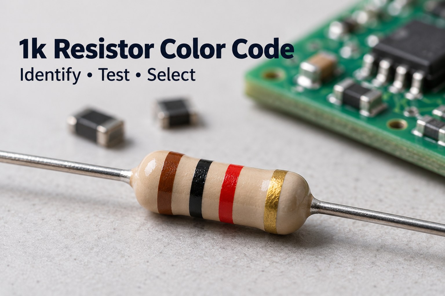
The 1k resistor color code is brown–black–red–gold for a common four-band resistor with ±5% tolerance. A five-band version with ±1% tolerance uses brown–black–black–brown–brown. Both represent 1,000 Ω, also written as 1 kΩ or 1k0. Surface-mount versions may carry the marking 102 or 1001, while smaller packages may be unmarked. Once you identify the value, check tolerance, power rating, and package before using the resistor in a circuit.
At EBest Circuit, we support component sourcing, PCB fabrication, and assembly. Send your BOM, Gerber files, and assembly requirements to sales@bestpcbs.com for a quotation, including manufacturer part numbers and approved resistor alternatives where available.
Key Takeaways
- A 1k resistor has a nominal resistance of 1,000 Ω; 1 kΩ, 1k0, and 1000 Ω describe the same value.
- Brown–black–red–gold identifies a four-band 1 kΩ resistor with ±5% tolerance, corresponding to 950–1,050 Ω under its specified reference conditions.
- Brown–black–black–brown–brown identifies a five-band 1 kΩ resistor with ±1% tolerance, corresponding to 990–1,010 Ω.
- In conventional SMD resistance coding, 102 and 1001 both represent 1 kΩ; the marking alone does not establish power rating.
- With 5 V directly across a 1 kΩ resistor, current is 5 mA and power dissipation is 25 mW.
- A resistance measurement should be taken with power removed and stored charge discharged; parallel circuit paths can make an installed resistor read below its individual value.
- A 1 kΩ resistor can serve as an LED current limiter, pull-up, pull-down, or part of an RC network when the circuit calculations support that choice.
- A suitable replacement must match resistance and meet the required tolerance, power, voltage, temperature, and footprint specifications.
What is a 1k ohm resistor?
The letter k means kilo, or one thousand, so a 1k resistor has a nominal resistance of 1,000 ohms. It belongs to a family of fixed-value components used to control current and establish voltage or timing relationships.
You may see the value written as 1 kΩ, 1k, 1K, 1k0, or 1000 Ω. In component-value notation, a letter can replace the decimal point: 1k0 means 1.0 kΩ, while 1k5 means 1.5 kΩ.
Keep the component value separate from its PCB reference designator. A label such as R12 identifies the resistor’s position in the circuit. The schematic or BOM supplies its resistance and other specifications.
Resistance also differs from power rating. A 1 kΩ, 0.125 W chip resistor and a 1 kΩ, 1 W leaded resistor have the same nominal resistance, but their permissible operating conditions differ. Selecting a part starts with the resistance value and continues with its electrical and mechanical ratings.
What color is 1k?
For a four-band resistor, the first two bands provide the significant digits, the third gives the multiplier, and the fourth indicates tolerance.
For brown–black–red–gold, brown represents 1, black represents 0, and red means multiply by 100:
10 × 100 = 1,000 Ω
The gold band specifies ±5% tolerance. A different final band changes the tolerance while the first three bands continue to indicate 1 kΩ.
The 1k resistor color code 5 band sequence follows the same digit-and-multiplier principle. Five-band resistors use three significant digits followed by a multiplier and tolerance band. Brown–black–black gives 100; the next brown band multiplies that by 10.
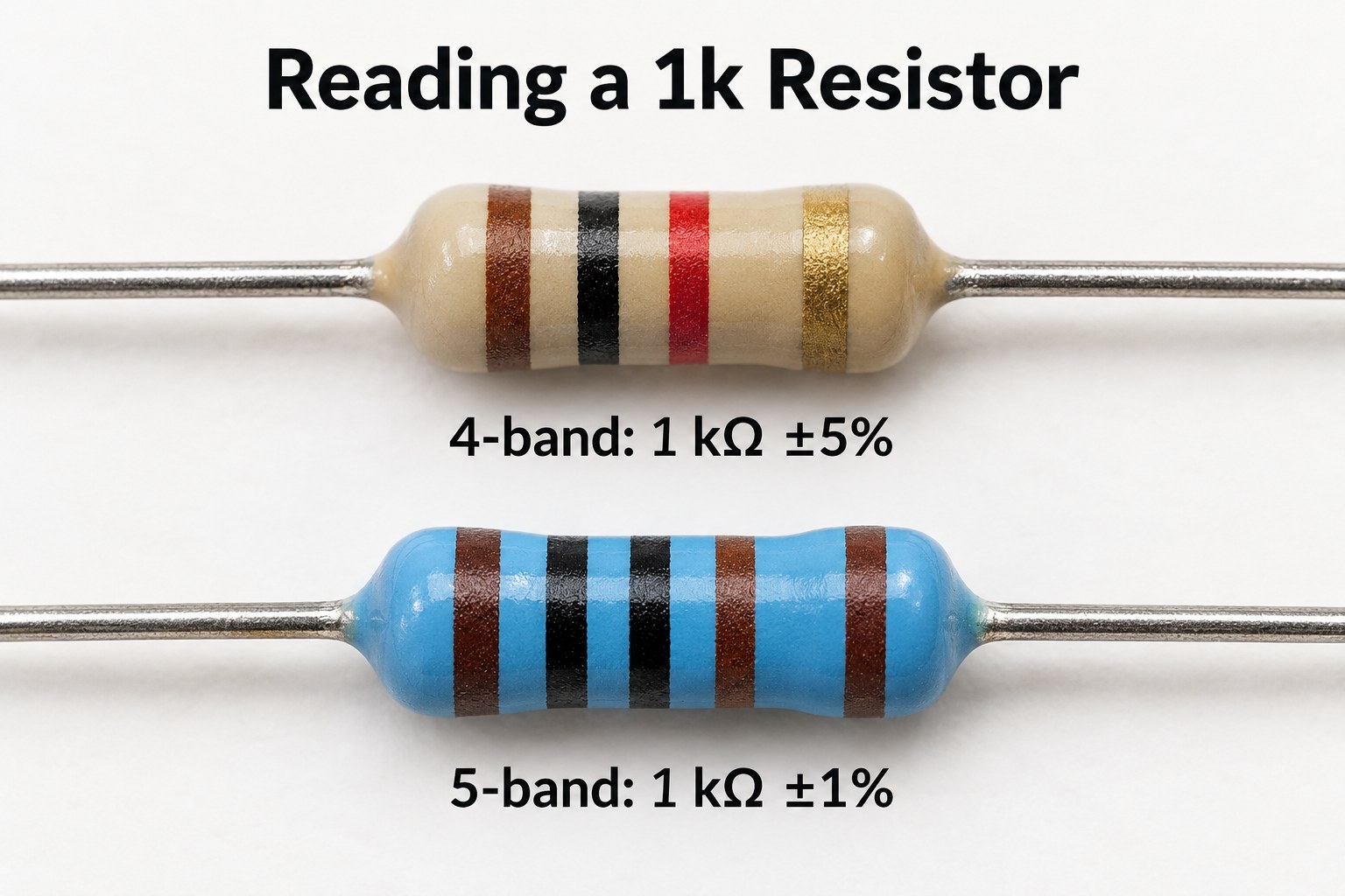
| Band format | Color sequence | Resistance calculation | Tolerance | Initial resistance range |
| Four-band | Brown–black–red–gold | 10 × 100 | ±5% | 950–1,050 Ω |
| Four-band | Brown–black–red–brown | 10 × 100 | ±1% | 990–1,010 Ω |
| Four-band | Brown–black–red–red | 10 × 100 | ±2% | 980–1,020 Ω |
| Four-band | Brown–black–red–silver | 10 × 100 | ±10% | 900–1,100 Ω |
| Five-band | Brown–black–black–brown–brown | 100 × 10 | ±1% | 990–1,010 Ω |
| Five-band | Brown–black–black–brown–red | 100 × 10 | ±2% | 980–1,020 Ω |
These ranges describe initial tolerance under the specified reference conditions. Operating temperature and long-term drift are separate considerations.
Read the bands with the tolerance band at the end; its spacing often helps establish direction. Body color is not a dependable resistance identifier. For faded or heat-damaged markings, confirm the value against documentation and an isolated measurement.
What Are the SMD Codes for a 1k Resistor?
The common three-digit SMD code for 1 kΩ is 102. The first two digits form 10, and the final digit specifies a multiplier of 10²:
102 → 10 × 10² = 1,000 Ω
The four-digit equivalent is 1001:
1001 → 100 × 10¹ = 1,000 Ω
Distinguishing these codes from similar markings prevents a tenfold value error during inspection or rework.
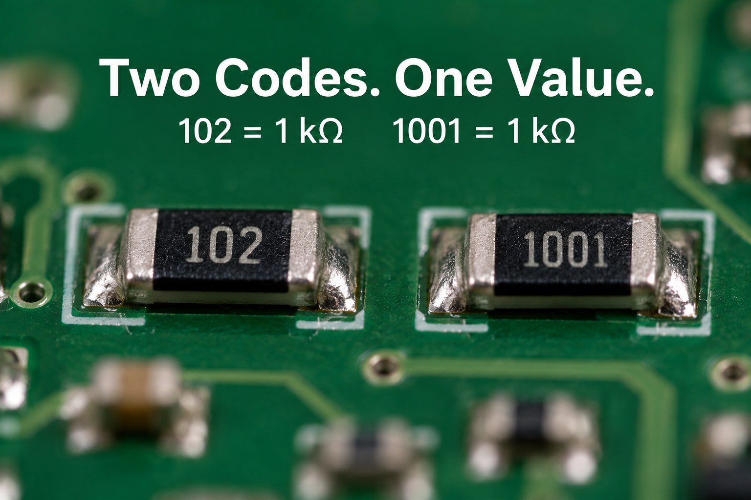
| SMD marking | Conventional interpretation | Resistance |
| 101 | 10 × 10¹ Ω | 100 Ω |
| 102 | 10 × 10² Ω | 1 kΩ |
| 103 | 10 × 10³ Ω | 10 kΩ |
| 1000 | 100 × 10⁰ Ω | 100 Ω |
| 1001 | 100 × 10¹ Ω | 1 kΩ |
| 1002 | 100 × 10² Ω | 10 kΩ |
A four-digit code of 1000 represents 100 Ω, not 1,000 Ω. Interpret the full marking system rather than reading the printed digits as an ordinary number.
Small chip resistors may have no readable marking. For these components, use the reel label, manufacturer part number, BOM, and placement records. A top-side photograph alone may be insufficient to distinguish several values in the same package.
How Do You Test a 1k Resistor with a Multimeter?
Use resistance mode and measure the component with the circuit unpowered. For a dependable component-level result, isolate the resistor from other conductive paths.
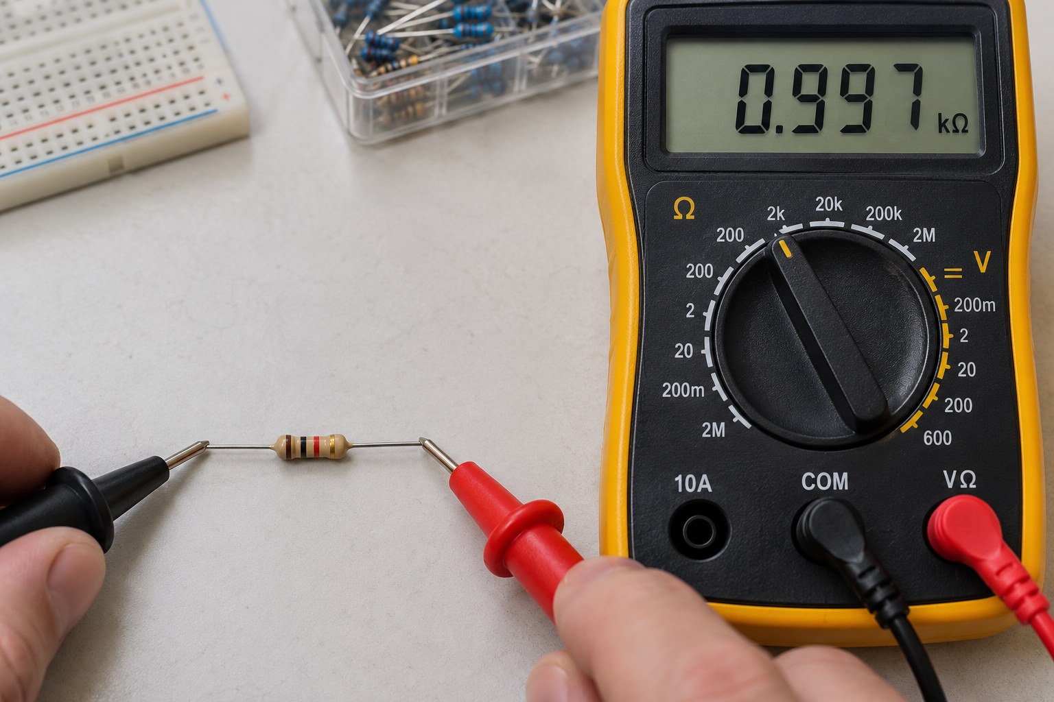
- Remove circuit power. Disconnect batteries, external supplies, and other sources that could energize the board.
- Discharge stored energy. Use an appropriate discharge method and verify that residual voltage has fallen before measuring resistance.
- Select the resistance function. Use autoranging or a manual range that includes 1 kΩ.
- Check probe contact. Touch clean terminals or pads and allow the reading to settle.
- Isolate the component if necessary. Lift one lead or remove the resistor when the surrounding circuit affects the measurement.
- Compare the result with its tolerance. Include the meter’s accuracy when judging a reading close to a limit.
For example, 997 Ω is within the initial range of a 1 kΩ ±1% resistor. A reading of 1,030 Ω fits a ±5% part but falls outside the initial ±1% range, assuming suitable measurement conditions and sufficient meter accuracy.
An installed resistor can read lower because the meter sees parallel paths. Two 1 kΩ resistors connected in parallel produce an equivalent resistance of 500 Ω. That reading says something about the network between the probes, rather than proving either resistor is faulty.
If a reading remains unstable, inspect probe contact, residual charge, and semiconductor paths before replacing the component. Document the measured value and test conditions when the result will be used for a production or repair decision.
How Much Current and Power Does a 1k Resistor Carry?
Current depends on the voltage across the resistor, while heating depends on the power dissipated in it.
Use:
I = V ÷ R
P = V² ÷ R = I² × R
For a nominal 1,000 Ω resistor, the following values apply when the stated DC voltage appears directly across its terminals.
| Voltage across resistor | Calculated current | Calculated dissipation | Selection implication |
| 3.3 V | 3.3 mA | 10.89 mW | Usually modest thermal loading; verify the selected part |
| 5 V | 5 mA | 25 mW | Compare with allowable power at operating temperature |
| 9 V | 9 mA | 81 mW | A 0.1 W part would operate at 81% of its nominal rating before derating |
| 12 V | 12 mA | 144 mW | Exceeds a 0.125 W nominal rating |
| 24 V | 24 mA | 576 mW | Exceeds a 0.5 W nominal rating |
These calculations use nominal resistance. At a fixed voltage, the lowest resistance within tolerance produces the highest current and dissipation.
For a 1 kΩ ±5% resistor with 12 V across it:
Pmax = 12² ÷ 950 ≈ 0.152 W
Include supply tolerance as well when establishing the worst operating case.
A useful power-based current calculation is:
I = √(Pallowable ÷ R)
For 1 kΩ and 0.25 W, this gives approximately 15.8 mA. It is a power-based boundary under the assumed conditions, rather than a recommended operating point. The selected part’s temperature derating, voltage limit, pulse capability, and mounting conditions still apply.
How Do You Choose the Power Rating and Package?
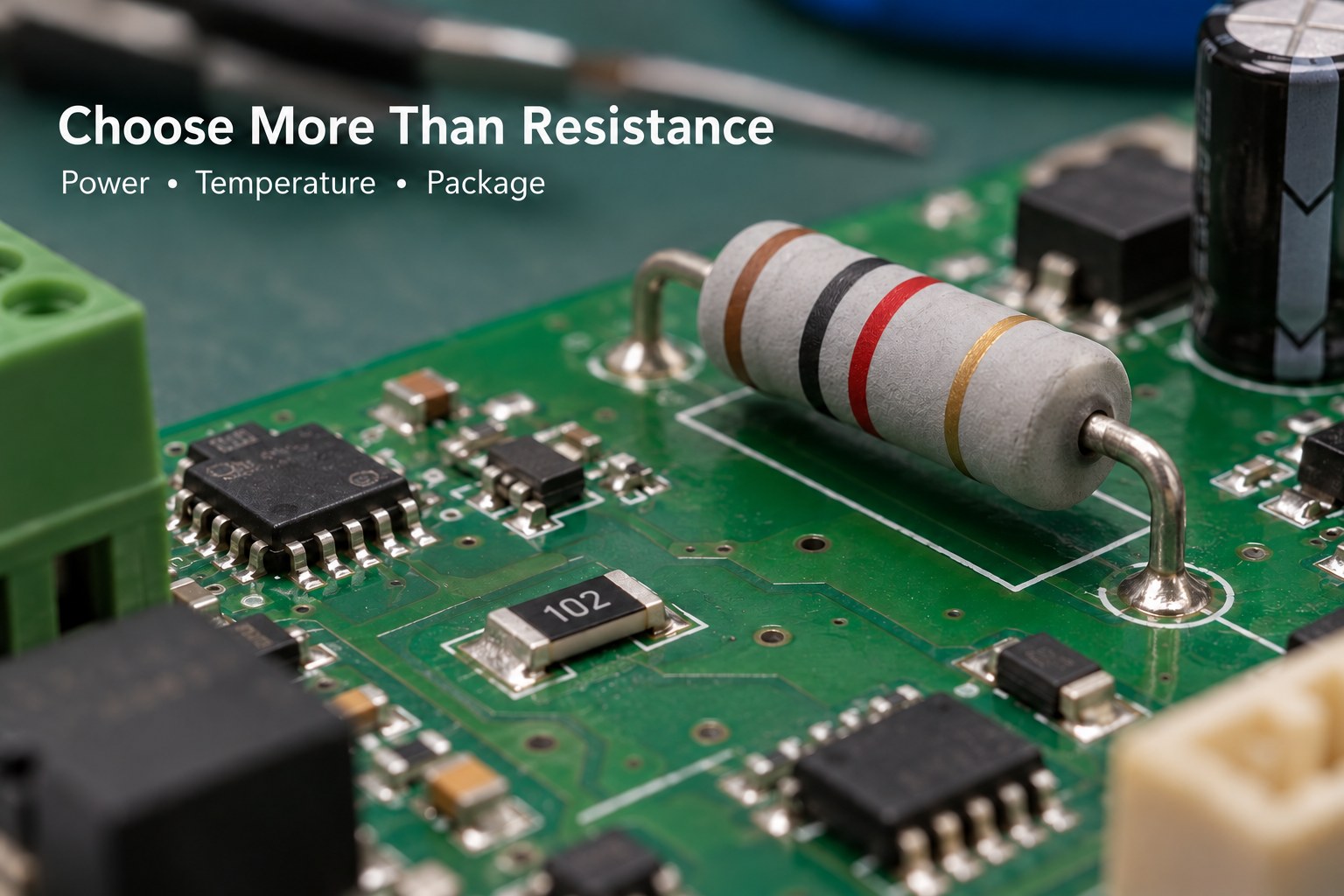
Choose the power rating from the highest expected dissipation and the allowable dissipation at the actual operating temperature. Then select a package that fits the PCB and can meet those conditions.
Package size does not establish a universal wattage. Resistor families with the same body dimensions can have different ratings, termination designs, and mounting requirements.
| Specification | What to define | Why it matters |
| Resistance | 1 kΩ nominal | Establishes the intended circuit behavior |
| Initial tolerance | For example, ±1% or ±5% | Sets the initial resistance spread |
| Rated power | Series-specific rating and reference temperature | Establishes the starting thermal limit |
| Temperature derating | Allowable power at the expected local temperature | Accounts for reduced cooling margin |
| Working voltage | Continuous voltage across the resistor | Adds a limit separate from power |
| Pulse capability | Pulse amplitude, duration, repetition, and waveform | Supports startup and transient evaluation |
| Temperature coefficient | Required ppm/°C range | Controls resistance change with temperature |
| Package and footprint | Imperial/metric size, pads, or lead spacing | Ensures mechanical and assembly compatibility |
| Resistor technology | Thick film, thin film, metal film, or another suitable type | Affects stability, noise, and pulse behavior |
| Procurement details | Manufacturer part number and approved alternatives | Keeps repeat builds consistent |
For reference, the standard-power ratings in Vishay’s D/CRCW e3 family include 0.10 W for 0603, 0.125 W for 0805, and 0.25 W for 1206 under the datasheet conditions. These are specific product-family examples, not ratings that apply to every resistor in those sizes.
Consider a hypothetical 0.25 W resistor whose datasheet specifies linear derating from full power at 70°C to zero at 155°C. At 100°C, its allowable power would be:
0.25 × (155 − 100) ÷ (155 − 70) ≈ 0.162 W
The earlier 12 V example dissipates 0.144 W nominally, leaving limited margin under those assumed conditions. A larger rating or a different circuit arrangement may provide a more suitable operating point.
What is a 1k ohm resistor used for?
A 1 kΩ resistor can limit current through an indicator LED when its calculated current meets the brightness requirement and remains within the component ratings.
For a simple series circuit:
ILED = (Vsupply − VF − Vdriver) ÷ R
Here, VF is the LED’s forward voltage and Vdriver is any relevant voltage drop in the driving transistor or output stage.
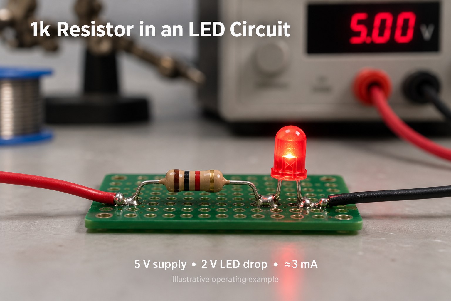
With an assumed 5 V supply, 2 V LED forward voltage, and negligible driver drop:
ILED = (5 − 2) ÷ 1,000 = 3 mA
The resistor sees 3 V, so its dissipation is:
PR = 3² ÷ 1,000 = 9 mW
This illustrates why the supply voltage should not automatically be used as the resistor voltage. Part of the supply appears across the LED.
For a second example, a 12 V supply and a 2 V LED forward voltage produce approximately 10 mA and 0.10 W in the resistor. Compare that dissipation with the selected resistor’s derated rating.
Check maximum supply voltage, minimum LED forward voltage, resistor tolerance, and the driver’s current capability when calculating the highest current. For minimum brightness, evaluate the opposite limits and the LED’s specified light output.
When Is a 1k Pull-Up or Pull-Down Resistor Suitable?
A 1 kΩ pull-up or pull-down provides a relatively strong bias compared with 10 kΩ. It can establish a logic state with less sensitivity to leakage current, while drawing more current when an output drives against it.
For a 3.3 V pull-up connected to an output held near ground:
I ≈ 3.3 ÷ 1,000 = 3.3 mA
The driving pin must support that current while maintaining a valid logic-low voltage. Account for any additional pull-ups already connected to the same net.
On an open-drain bus, resistance also affects rise time. A lower pull-up resistance charges bus capacitance faster, but increases the low-state current requirement. TI’s I²C guidance calculates a lower resistance limit from output sink capability and an upper limit from rise time and bus capacitance.
For a simple RC rise measured from 30% to 70% of the supply:
tr ≈ 0.8473 × R × C
With 1 kΩ and 100 pF, the calculated rise time is approximately 84.7 ns. Use the actual interface requirements and connected-device specifications to judge suitability.
For a static input or battery-powered circuit, a higher resistance may provide adequate bias with lower current consumption. Select the value from leakage, noise exposure, timing, and power requirements.
How Do Tolerance and Temperature Affect Circuit Accuracy?
Tolerance describes the initial resistance range. Temperature coefficient describes how resistance changes with temperature, commonly expressed in parts per million per degree Celsius.
Using a simplified linear estimate:
ΔR = R × TCR × ΔT
For a 1 kΩ resistor with a temperature coefficient magnitude of 100 ppm/°C over a 50°C change:
|ΔR| ≈ 1,000 × 100 × 10⁻⁶ × 50 = 5 Ω
That is approximately 0.5% of nominal resistance. Initial tolerance, self-heating, and long-term drift are separate contributors to the total error budget.
In a voltage divider, the resistance ratio determines the unloaded output. Two nominal 1 kΩ resistors across 5 V produce 2.5 V at their midpoint.
If both resistors are ±1%, opposing tolerance extremes give:
Vout,min = 5 × 990 ÷ (1,010 + 990) = 2.475 V
Vout,max = 5 × 1,010 ÷ (990 + 1,010) = 2.525 V
Loading adds another source of error. A 10 kΩ load connected from the midpoint to ground is in parallel with the lower 1 kΩ resistor. Their equivalent resistance is approximately 909 Ω, reducing the nominal output to about 2.381 V.
For an RC network, a 1 kΩ resistor and 100 nF capacitor give a nominal time constant of 100 µs. Both component tolerances influence the result, so choose their specifications together.
Can You Replace a 1k Resistor with Another Value?
A different resistance is suitable only when the resulting circuit behavior remains acceptable. A change that works in an indicator circuit may alter an analog gain, timing interval, or protection function beyond its intended range.
For a temporary equivalent resistance:
- Two 500 Ω resistors in series produce 1 kΩ.
- Two 2 kΩ resistors in parallel produce 1 kΩ.
- A 680 Ω resistor and a 330 Ω resistor in series produce 1,010 Ω, which is 1% above 1 kΩ before component tolerances are included.
Evaluate power in each resistor separately. With two equal 2 kΩ resistors in parallel, each sees the full applied voltage and ideally dissipates half the total power. Actual ratings and thermal coupling determine whether the arrangement is suitable.
For a production replacement, retain the required resistance and review tolerance, power, working voltage, temperature coefficient, pulse behavior, and footprint. A higher wattage part can be useful if its dimensions and other properties fit the design.
At EBest Circuit, providing approved manufacturer part numbers and alternatives helps us coordinate sourcing with the assembly BOM. Identify any resistor positions with critical accuracy or pulse requirements so those limits remain visible during substitution review.
FAQs About 1k Resistors
Q1: Does a 1k resistor have polarity?
A1: A standard two-terminal fixed resistor is nonpolarized and can function electrically in either orientation.
Q2: Should a good 1k resistor make a continuity tester beep?
A2: Many meters have a continuity threshold well below 1 kΩ, so use resistance mode and read the displayed value.
Q3: Does the sixth band on a resistor add another resistance digit?
A3: In a common six-band system, the sixth band indicates temperature coefficient; confirm the marking convention for the selected series.
Q4: Can a 1k resistor replace a fuse?
A4: A standard resistor does not provide a fuse’s specified interruption behavior; use the protection component required by the circuit design.
Q5: Does a blue resistor body always mean 1% tolerance?
A5: Body color varies between products, so establish tolerance from the bands, part number, or datasheet.
Q6: Can a resistor pass a resistance test and still fail during operation?
A6: Yes, a low-power resistance measurement may miss faults that appear under heat, voltage stress, or mechanical movement.
Q7: Is a 1k resistor suitable for every transistor base connection?
A7: The appropriate base resistance depends on drive voltage, required collector current, switching conditions, and the transistor’s specified behavior.
How Can EBest Circuit Support Your PCB Assembly?
At EBest Circuit, we support PCB fabrication, component sourcing, and assembly for prototypes and production builds. Share your component requirements early so we can review BOM completeness, resistor footprints, sourcing options, and the inspection or testing needed for your board.
For a quotation, send your Gerber files, BOM, pick-and-place file, assembly drawings, quantities, and test requirements to sales@bestpcbs.com. Include approved alternatives and any critical resistance tolerance, power, temperature, or pulse requirements to help us prepare the build accurately.